B&PLUS Wireless Power Supply RS24E-424N-PU Series User manual

Remote System
User’s Guide
https://www.b-plus-kk.jp/ E-mail seles@b-plus-kk.jp
4.4
Φ
45.0
(3.0)
55.0
55.0
45.0
30.0
Remote sensor sysytem
24 signal transmission / Compact shape
24V1A type
Output sensor:RS24E-424N-PU-_ _ , RS24E-424P-PU-_ _Transmitter : RS24T-424-PU-_ _
【Function of each component】
Detector : Connects Detector sensor (max.24) and transmits the detected signals to Transmitter.
Transmitter : Provides power for Detector, also passes detected signals from Detector to Output Sensor.
Output Sensor : Puts out detected signal to external controller, also sends power for operating of Detector and Transmitter.
System conguration
Dimension
Specication of the System
Available sensors
LED indication
■ Status LED(Green)
■ In zone LED (Orange)
RS24ERS24T Host device
External Power
Unit(24V DC )
DC3-wire,
sensor
The in zone LED lights up when the transmission part and the output part are in a confronting state and communication is possible.
Typical Transmitting Diagram
(Supply voltage at 24V /non-ush mount)
X:Center offset(mm)
Y:Operating distance(mm)
2021.12.21
[ Detector ]
Detected
signal
Detected
signal
max.24 signals
Power
supply
Power
supply
24V DC
[ Transmitter ]
Signal
transmission
[ Output sensor ]
LED
Lighting pattern
Meaning
ON - - The power supply is supplied.
OFF - - The power supply is not supplied.
Blink Slow
(1.5 sec)
O time of the LED is long Anomalous temperature
Blink
Lighting time of the LED is long
Oscillation circuit overcurrent.
Blink
Mid.Speed
(0.6 sec)
O time of the LED is long Supply voltage is high.
Blink
Lighting time of the LED is long
Supply voltage is low.
Blink
High speed
(0.2 sec)
The LED ashes at the
same interval
Short circuit protection.
ON
OFF time of the
LED is long
Lighting time of the
LED is long
ON
OFF
OFF
Operating area Operating area
Drive current ≦ 0.5A
Output sensor:RS24E-424N-PU-_ _(NPN)
Transmitter: RS24T-424-PU-_ _
T319301Fe
Supply voltage 24V DC
Total currenconsumptoion ≦ 1A
Residual voltage ≦ 6.5V
Load current -
*¹【RB】represents robot cable specications.
*² Indicates the time from when the remote and base sections are energized in the transmittable area to when non-contact signal transmission is possible.
*³ Metal protection is a function to prevent metal heat generation when facing metal, and is not guaranteed to work on all metals. Do not intentionally place metal against the communication surface.
RS24E-424P-PU-_ _(PNP)
Type
RS24T-424-PU-_ _
Applicable sensor
DC 3-wire sensor
Drive voltage
(Output voltage)
24V ± 1.5V DC
Drive current tota
l
≦ 1A
Input signals 24
(SI1… 24) and a switching signal(NPN / PNP)
Operating
distance
in the case of 1A
0...4mm
in the case of 0.5A
0...6.5mm
Center oset (1A)
± 6mm :
Transmission distance is within 3mm
± 2.5mm:
Transmission distance 3...4mm
Center oset(0.5A)
± 8mm :
Transmission distance is within 4.5mm
± 3mm :
Transmission distance 4.5...6.5mm
Operating temperature
0...+50℃
Protection class
IP67
Cable
PUR φ 8.6x2(2x0.5mm
2
+13x0.18 mm
2
)+(12x0.18 mm
2
)
【RB】
*¹
Material
Case Polyurethane
Heat sink
Aluminum
Weight Body 165g +Cable 105g/m x2pcs.
Type NPN RS24E-424N-PU-_ _
PNP RS24E-424P-PU-_ _
Supply voltage(Input voltage)
24 V DC ± 5 %
Current
consumption
active Max 1.5 A (with 1A drive)
static Max 0.1 A (when not facing)
Number of output signals
24+1(In zone)
Load current ≦ 50mA/ 1output
Startup time
≦ 0.2sec*²
Frequency of operation
300Hz
LED indication
Status (Green), In zone (Orange)
Operating temperature
0...+50℃
Protection class
IP67
Protection circuit
Reverse connection protection, overheat protection,
short circuit protection,
overcurrent protection Output surge absorption
protection, head metal facing
protection *³
Cable
PUR φ 8.6x2(2x0.5mm2+13x0.18 mm 2)+(12x0.18 mm 2)
Material
Case Polyurethane
Heat sink
Aluminum
Weight
Body 165g+ Cable 105g/m x 2pcs.
Use a sensor that operates correctly within the
conditions in the table below.
In zone LED
Status
LED
(L)
Cable 1
Cable 2
Marking tube
Drive current ≦ 1A
Y
X
(3.0)
55.0
45.0
Φ
4.4
45.0
55.0
30.0
Cable 1
Cable 2
L=Cable length
The notation in meters to
the end of the model
・・・PU-02 ⇒ 2m
max. 5m
(Transmitter,Outputsensor)
(L)
0.5A
X
Ymm
-12 -9 -6 -3 0
10
8
6
4
2
12963
1A
X
Ymm
-8 -6 -4 -2 0
5
4
3
2
1
8642
RS24T-424-PU-_ _
Cable 1 (with marked tube)
Output+24 V WH
Output0V PaleBU
Polarity switching POL
BK Cable 2
Input 1(SI1) BN Input 13(SI13) GN *■ ■
Input 2(SI2) RD Input 14(SI14) BU *■ ■
Input 3(SI3) OG Input 15(SI15) VT *■ ■
Input 4(SI4) YE Input 16(SI16) GY *■ ■
Input 5(SI5) GN Input 17(SI17) BN **
■ ■
Input 6(SI6) BU Input 18(SI18) RD **
■ ■
Input 7(SI7) VT Input 19(SI19) OG **
■ ■
Input 8(SI8) GY Input 20(SI20) YE **
■ ■
Input 9(SI9)
BN
*■ ■ Input 21(SI21) GR **
■ ■
Input 10(SI10)
RD
*■ ■ Input 22(SI22) BU **
■ ■
Input 11(SI11)
OG
*■ ■ Input 23(SI23) VT **
■ ■
Input 12(SI12)
YG
*■ ■ Input 24(SI24) GY **
■ ■
RS24E-424N/P-PU_ _
Cable 1 (with marked tube)
Input+24 V WH
Input 0V PaleBU
In zone Iz BK Cable 2
Output1(SO1) BN Output13(SO13) GN *■ ■
Output2(SO2) RD Output14(SO14) BU *■ ■
Output3(SO3) OG Output15(SO15) VT *■ ■
Output4(SO4) YE Output16(SO16) GY *■ ■
Output5(SO5) GN Output17(SO17) BN **
■ ■
Output6(SO6) BU Output18(SO18) RD **
■ ■
Output7(SO7) VT Output19(SO19) OG **
■ ■
Output8(SO8) GY Output20(SO20) YE **
■ ■
Output9(SO9)
BN
*■ ■ Output21(SO21) GR **
■ ■
Output10(SO10)
RD
*■ ■ Output22(SO22) BU **
■ ■
Output11(SO11)
OG
*■ ■ Output23(SO23) VT **
■ ■
Output12(SO12)
YE
*■ ■ Output24(SO24) GY **
■ ■
Wiring color
■ Polarity switch POL is used to switch the polarity (NPN/PNP) of the sensor connected to the transmission unit.
Check the wiring diagram, and wire it according to the sensor to be connected. If it is not wired, no signal will be detected.
■ When shipped from the factory, the unused core wire of the cable is cut. If the cable is shortened for wiring reasons, the unused
core wire will be exposed. If you shorten the cable for wiring reasons, the unused core wire will be exposed, so please take care
not to short-circuit the cable. Unused wires are as follows: Cable 1: Green*, Blue*, Purple*.
Cable 2: brown*, red*, orange*, yellow*, white, empty. (* indicates a wire with ■ ■ or ** printed on the core wire of each color.)
Wiring Diagram
<When connecting a 3-wire NPN type detection sensor>
Detection sensor
(NPN)
Detection sensor
(DC2W)
(+)
(-)
(出力)
(POL)
(+)
(-)
(SI)
RS24T
Detection sensor
(PNP)
(+)
(-)
(出力)
(POL)
(+)
(-)
(SI)
RS24T
(+)
(-)
(POL)
(+)
(-)
(SI)RS24T
Detection sensor
(DC2W)
(+)
(-)
(POL)
(+)
(-)
(SI)
RS24T
1~2KΩ
PLCRS24E
(+)
(-)
(Iz)
(SO)
<
When connecting a 3-wire PNP type detection sensor
>
<In case of 2-wire detection sensor connection (NPN setting)
>
<In case of 2-wire detection sensor connection (PNP setting)
>
<Connecting to an external PLC, etc.>
1~2KΩ
■When wiring, please check the wiring diagram carefully
to ensure that the wiring is correct.
■When connecting a DC 2-wire sensor, wire a resistance of
about 1 to 2kΩ.
The following is an explanation of the protection functions provided.
Reverse connection protection ... When 24V and 0V are connected in reverse on the power line of the output section, this function turns o the output for a certain
period of time to protect the circuit.
Overheat protection ... is a function that measures the temperature inside the output section and stops the power supply when the temperature exceeds a certain level.
When the temperature drops, it restarts.
Short-circuit protection ... This function turns o the output for a certain period of time to protect the circuit when a current exceeding the specication ows through
the signal output line due to wiring without load.
Overcurrent Protection ... This function detects the current inside the output section and stops transmitting for a certain period of time when the current exceeds a
certain value, thereby protecting the circuit.
Output surge absorption protection...A surge absorption circuit is built in to protect the output circuit.
Head metal confrontation protection ... This function protects the circuit by stopping transmission for a certain period of time when metal is detected.
Protection function
・
Do not disassemble or modify our products. It may cause a malfunction, re, electric shock, etc., or cause serious damage.
In addition, the warranty will be void if the product is disassembled or modied.
・
If you are in an abnormal condition such as smoke, abnormal noise, or strange odor, discontinue use immediately as there is
a risk of malfunction, re, electric shock, or accident.
・Be sure to use accessories and specied parts. If you do not use it, it may cause malfunction, accident, malfunction, re, etc.
・
If you add or move equipment, please check the installation conditions again.
・
When disposing of this product, dispose of it as industrial waste.
■ About product handling
Other notes Other notes
・The control communication device installed in the product corresponds to a "weak radio station (weak radio wave
device)", so the Minister of Internal Aairs and Communications' radio station permit (diploma) is not required.
However, please be careful when operating it as it may aect electronic devices and medical devices (pacemakers, etc.).
■Standards and regulations
・
A remote sensor system is a system that supplies and transmits power and signals in a non-contact manner. Please do not use it
for any purpose other than this purpose.
・Design with the combination described in the instruction manual or user's guide. Opposition in any other combination may
cause malfunction or damage.
・
Use a constant voltage power supply such as a switching power supply.
(If a power supply with ripples above the rating, such as a full-wave rectied power supply, is used, it may cause malfunction.)
・
If the power supply exceeds the rated voltage, there is a risk of overheating and ignition.
Before supplying power, be sure to check that the power supply is specied in the specications.
・
Design it so that it can be used under the wiring and surrounding environment conditions specied in the specications. Also,
design to satisfy the "transmission distance", "axis deviation", "drive voltage", and "drive current". Designs outside the
specications may cause unexpected malfunctions, troubles, and malfunctions due to deterioration of internal parts.
・
When wiring for installation, maintenance, failure, etc., be sure to check that the main breaker (power panel) is cut before
performing the work. If you work while the line is live, you may get an electric shock or malfunction.
・
As with other electronic devices, inrush current may be generated when the system starts up, so please set the power
supply in consideration of the inrush current.
・
Design the system so that the entire system works safely even if the external power supply is abnormal or the product fails.
・
This product is designed for indoor use. Be sure to use it indoors. Use outdoors may cause an accident, malfunction or re.
Product failures due to mishandling are increasing.
Please be sure to read this manual, and if you have any concerns,
please contact the following before energizing.
https://www.b-plus-kk.jp/ E-mail [email protected]
Precautions for installation and design
・
Please note that the contents and specications of this manual are subject to change without notice.
If you have any questions about the contents of this manual, please contact us.
■
Be sure to check it as there are various dangers such as failure if it is installed incorrectly.
・
To avoid heat generation and ignition due to induction heating, do not put metal
objects between the operating heads.
・
To avoid heat generation and unexpected accidents, remove metal chips and
cutting chips from the transmission surface of the head.
・
To avoid damaging the product due to abnormal heat generation, do not hold the transmission distance
/ axis deviation / overload condition outside the specications for a long time.
・
I
mpact and external noise may cause malfunction or failure. Route the cable away from power lines and high-voltage
equipment without giving a shock. (Fig. 5)
・
Make sure that the total current consumption of the connected devices does not exceed the drive current value.
・In order to consider and reduce the self-heating of this product, take measures so that it can be used below the specied ambient temperature.
・
To reduce the eect of self-heating (heat dissipation), it is recommended to mount it on metal using case mounting screws
.
・
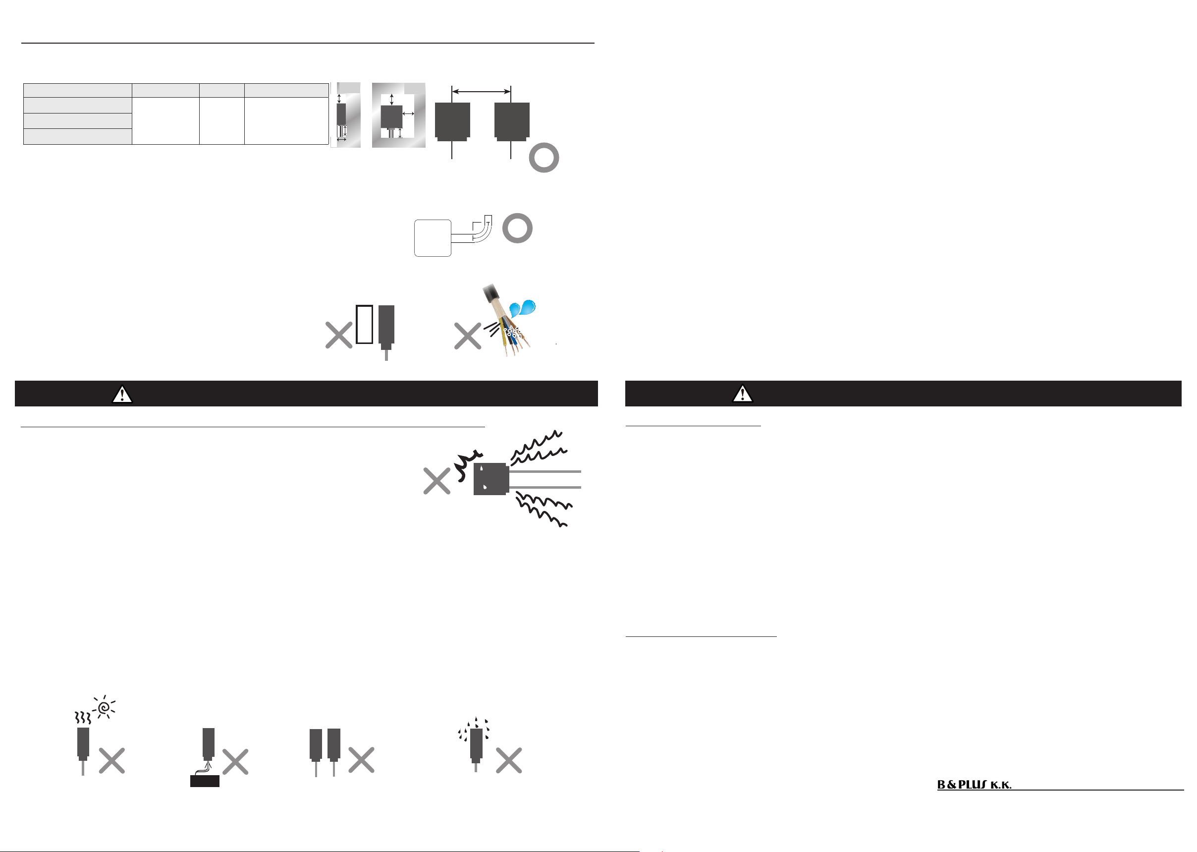
If it is installed in a place where it is exposed to direct sunlight or hot air from a heater, it may cause a re or malfunction. (Fig. 6)
・If you apply power to the transmitter or energize either one with the output sensor facing each other, a failure may occur. (Fig. 7)
・
Please use in an environment where it is not exposed to organic solvents or liquids containing them. (Fig. 8)
impact
Power lines and high-voltage equipment
noise
(+_+) (+_+)
DC24V
( 一 _ 一;)
(;一 _ 一 )
(+_+)
Direct sunlight and hot air Energized by facing each other Liquids such as organic solvents
(Fig. 6) (Fig. 7) (Fig. 8)
(Fig. 5)
(Fig. 2) Cable bending radius
Type code A
(Surroundings)
B(
depth
)C
(Parallel installation)
RS24T-424-PU-_ _
30mm 30mm 165mm
RS24E-424N-PU-_ _
RS24E-424P-PU-_ _
・
When wiring the cable by bending it, use the cable outlet.
Install so that the cable is straight (approximate: about 10 mm)
Install the cable with a bending radius of 50 mm or more. (Figure 2)
・
Excessive force on the cable during installation to avoid excessive
stress Please do not pull with.
・
Fix the cable so that the sensor, the base of the sensor, and the
cable itself are not shaken or shocked.
・
Since metal overheating and internal elements may be damaged,
install the output part so that it does not face metal, and then
turn on the power. (Fig. 3)
・
If water, metal objects, or foreign matter get inside the device from
the end of the cable, it may cause re, smoke, re, electric shock,
or malfunction due to malfunction or short circuit. (Fig. 4)
Installation method
Metal facing output
( 一 _ 一;)
(Fig. 3) (Fig. 4)
(Fig. 1) Arranged with a space
metal
moisture
C
(^_^) (^_^)
Top view
Side view
A
B
金属
A
A
金属
50mm
AA
A
A
金属
A
A
金属
metal metal
((+_+))
metal
Power application
Outputsensor
Transmitter Outputsensor
Foreign material
Foreign material invades inside the sensor
Output sensor
・
To avoid the inuence of surrounding metals and mutual interference between products, be sure to open a space larger
than the value shown in the table below. In addition to the mounting surface, only one surface of A (periphery) can
be in contact with metal. (Fig. 1) The screw tightening torque is 1.5N・m.
This manual suits for next models
2
Other B&PLUS Power Supply manuals


