B&PLUS RCS Series User manual
RemoteSystem
User'sGuide
AttentionforInstallation
(Readthissectionthoroughlybeforeinstallation.)
Before using the Remote Sensor, read this manual carefully.
Duringinstallationandoperation,paycloseattentiontothe
safetyaspect.
◆ PleaseturnofftheRemoteSystembeforeanyperformances
suchasmounting,maintenanceorbreakdown.
◆ Ensurecorrectconnectionsbyreferencetothewiringdia-
gram.
◆ Toavoidmalfunctioncausedbyinductionnoise,cable
shouldbekeptapartfrommotororotherpowercable.
◆ Workforawhileorimmediatelyafteroperation,pleasedo
nottouchthe(powersupplyunit,chargingUnit,Headpart)hot
spots.Doingsocouldresultinburns.
◆ Thisproduct,whichisoneofthosehighfrequencyutiliza-
tionequipmentofRadioLaw,UponuseYouwillneedtoinstall
application.Pleaseuseitafteryouhavemadetheapplication
withoutfail.Installationdetailsoftheapplicationprocedure,
seeTelecommunicationswebsiteoftheMinistryofInternal
AffairsandCommunications,Please.
◆ ThisproducthasbecomeaJapannationalspecification.It
cannotbeusedoutsideofJapan.Itcannotbeusedoutside
ofjapan.WhenusedoutsideofJapan,Iguessweassumeany
liabilityYou.
(Former NIHON BALLUFF co., Ltd.)
Mail:[email protected]Web:http://www.b-plus-kk.com
WirelessPowerSupplyby
2017.07.26 T313402He
RemotePowersupplysystem
210WspecificationRCSseries
Chargingunit:RCS210-PB24
PowerSupplyunit:RCS240-AC1
PassiveHead
ActiveHead:RCS240AH
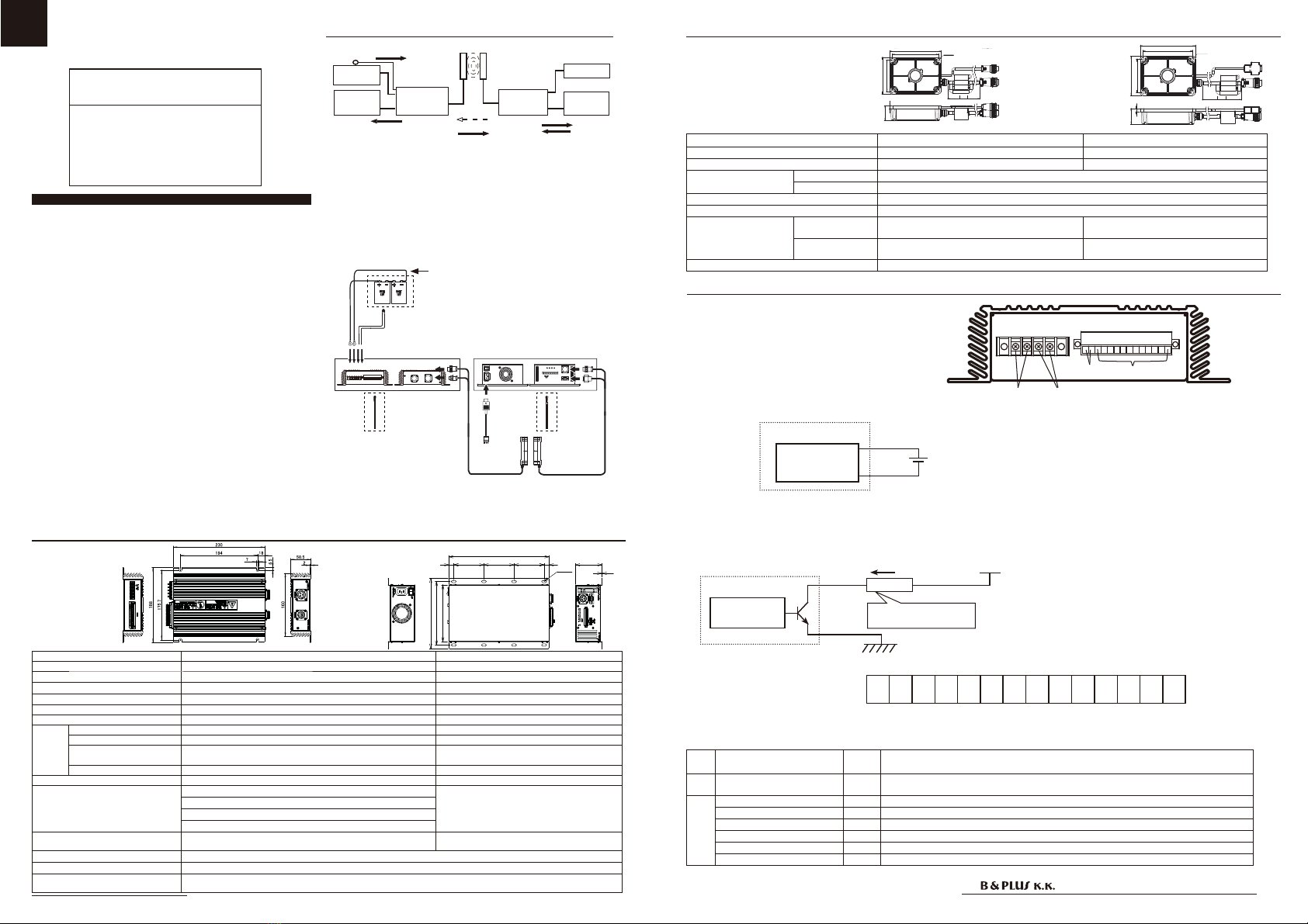
Systemconfiguration
Dimension
Specification
RCS210-
PB24 External
control
devices
External
control
devices
ACPower
24V
leadbattery
RCS240AHRCS240PH
RCS240-
AC1
【Functionofeachcomponent】
Powersupplyunit:Iwillconverttothehigh-frequencypowersupply,the
ACpower.Further,inresponsetothe(powersupplystartsignal)input
signals,suppliesahighfrequencypowertotheActivehead,and
outputcontrolequipmentinZonesignalandvarioussignalsActive
headisreceived.
Chargingunit:AndisChargingtothebattery.Itregularlymonitorsthe
batteryvoltageandoutputvoltage[batterymonitorsignalH,M,L]as
theresult.
Head:Icancarryavarietyofsignalandpowertransmissionina
non-contact.
[PassiveHead]
RCS240PH
PassiveHead ActiveHead
Typecode RCS240PH RCS240AH
Applicationchargingunit/powersupplyunit
RCS210-PB24 RCS240-AC1
Ratedgap Distance 10mm
Centeroffset Thesumtotalofgapoflengthandwidthis10mmorless.
Operating/Storagetemperature 0 〜 50℃ /-10℃〜 50℃
Protectionclass IP65
Connection
(Withtheconnector
cable1m)
Supply ConnectedtotheChargingunitatthe(fe-
male)3-pinround
ConnectedtotheChargingunitatthe(male)
3-pinround
Signal
ConnectedtotheChargingunitatthe(female)
5-pinround
ConnectedtotheChargingunitatthe
(male)D-sub9pin
Accessories 4screwsM6x15,Oneferriteclamp
【Connectiondiagram】
Powersupply
Signaltransmission Varioussignaltransmission
Varioussignaltransmission
Chargingunit PowerSupplyunit
Typecode RCS210-PB24 RCS240-AC1
Ratedinputvoltage − AC100V/AC200V
Outputvoltage/current Max30V/Max7A −
Currentconsumption − 4A
Operating/Storagetemperature
0 〜 40℃ /0 〜 50℃ 0 〜 50℃ /0 〜 50℃
Protectionclass IP20 IP20
Connec-
tion
Powersupply/signal Round3pin/Round5pin Round3pin/D-sub9-pin
Power − 3Pinlet
Terminalblock
Batteryconnection(2-pole),Thermistorconnection(2-pole),
Terminalwidthis6.2mmorless,TerminalscrewsizeisM3.
−
Varioussignalconnector
Refertothefollowingpage"wiring." Refertothefollowingpagewiring.
Coolingmethod Naturalaircooling Forcedaircooling
Protectioncircuit Inputovervoltageprotection −
Batteryhightemperature/lowtemperatureprotection
Batterynotconnectedprotection
Batteryreverseconnectionprotection
Accessories
Outputcable(1.5m),Thermistorwithcable(1.5m),
Externaldevicecommunicationconnector,4screwsM6x15
Powercable(2m),Externaldevicecommunication
connector,4screwsM6x15,Oneferriteclamp
Paralleldriving
None
Seriesdriving
Avaiable
Signaloutputtimerequired
Upinzonesignallightfromenteringtheheadtransmissionarea≦ 5s
Tostartchargingfromthein-zonesignallights≦ 5s
(1)Partsofthedottedline(Externaldevicecommunicationcable
and24Vleadbatteries)withintheproductisnotincludedwiththis
product.
Theyarecontentspreparedandprocessedofavisitor.
(2)Ihave youusetheattached articlealways,please pasteitinto
thetopportionofthe terminal near the 24V lead battery thermis-
tor.Inthecase,pleasedonottouchanyterminals.
(WirelessPowerSupply)
【Chargingunit】【Power
Supplyunit】
【Head】
Chargingunit PowerSupplyunit
Passive
Head ActiveHead
Power
cable
Outputcable
(2)
ThermistorwithCable
(1)24Vleadbattery
(1)
Externaldevice
communication
cable
(AWG24 〜 16)
(1)
External
devicecom-
munication
cable
(AWG28
〜 16)
[PowerSupplyunit]RCS240-AC1
1
8-7X15
170
190
210
15 90 90 90 15 80
300
[ActiveHead]
RCS240AH
Temperaturecontrol
Wiring
Signaltype Pin
number
Contents
Input Voltagemonitorrequest 1.2 Itmonitorsthebatteryvoltageandthevoltageappliedtothispin, andtheoutput
voltagemonitorsignal.
Out-
put
VoltagemonitorsignalH 3.4 Itisalmostfullycharged.(Chargingaim:about90%)
VoltagemonitorsignalM 5.6 Ifthechargehasbeenreducedsomewhat.(Chargingaim:about70%)
VoltagemonitorsignalL 7.8
Itneedschargingforchargingamountisreduced.(Chargingaim:lessthanabout50%)
Floatchargingsignal 9.10 Itturnson,whenachargingcurrentvalueturnsintoaratedvalue.
chargingsignal 11.12 IwillturnOFFduringchargingON,inchargecut-offandfloatchargingstart.
Errorsignal 13.14 Itturnson,ifabatteryerroroccurs.
● Chargingside(RCS210-PB24)
②①
④
1234567891011121314
③
① Theoutputterminalforbatteries
② Theterminalforthermistor
③ Inputsignal(voltagemonitorrequestsignal)
Eachoutputsignalisopen-collector.Themaximumcurrentvalueandthemaximum outputvoltage,pleaseconnectso
asnottoexceedthemaximumvaluebyreferringtothefollowingvalues.
Connecttheloadbeforedoingso,pleasedonotshort-circuittheoutputsignal.
● Maximumloadcurrent:5mA
● Maximumloadvoltage:24V
Internalcircuit
Vcc
Chargingunit
I
Tofiteachcondition,
pleaseselecttheload
Load
<Inputsignalpinassignment>
④ Outputsignal
Internalcircuit
Chargingunit
Vin
7.5 〜 30V
Otherthanatthetimeofcharging,Itisusedwhenyouwanttooutputthebatteriesvoltagemonitorrequestsignal.
L+L-
M+M-
H+H-F+F-C+C-N+N-
12 3456 7891011121314
+−
Specification
Dimension
[Thermistor]
+
−
〇+
〇−
:RCS240PH
[Chargingunit]RCS210-PB24
● Inputcurrent:100mA
● Inputvoltage:7.5V 〜 30V
※ Eachcable,please
connectwiththespecified
length.
Youmayreceiveanerror
duetotheoutputsuchasa
decreaseoccurs.
Pleaserefertothe
[Mountingoftheferrite
clamp]oftherearsurface.
䢢䢳䢴䢸䢢
䢢䢺䢸䢢
ఏ㏦㒊
ἲ
䢶䢯䪻䢸䢰䢷
䢢䢳䢶䢲䢢
䢢䢳䢲䢲䢢
䢢䢳䢲䢲䢲䢢
䢢䢺䢢
䢢䢶䢲䢢
䢢䢳䢴䢸䢢
䢢䢺䢸䢢
䢢䢳䢴䢸䢢
䢢䢺䢸䢢
䢶䢯䪻䢸䢰䢷
䢢䢳䢲䢲䢢
䢢䢳䢶䢲䢢
䢢䢳䢲䢲䢲䢢
䢢䢺䢢
䢢䢶䢲䢢
䢢䢳䢴䢸䢢
䢢䢺䢸䢢
RemoteSystem
User'sGuide
(Former NIHON BALLUFF co., Ltd.)
Mail:[email protected]Web:http://www.b-plus-kk.com
WirelessPowerSupplyby
Surroundingmetal Mutualinterference
Typecode C(mm)
RCS240AH 300
RCS240PH
Typecode A(mm) B(mm) C(mm)
RCS240AH 100 40 45
RCS240PH
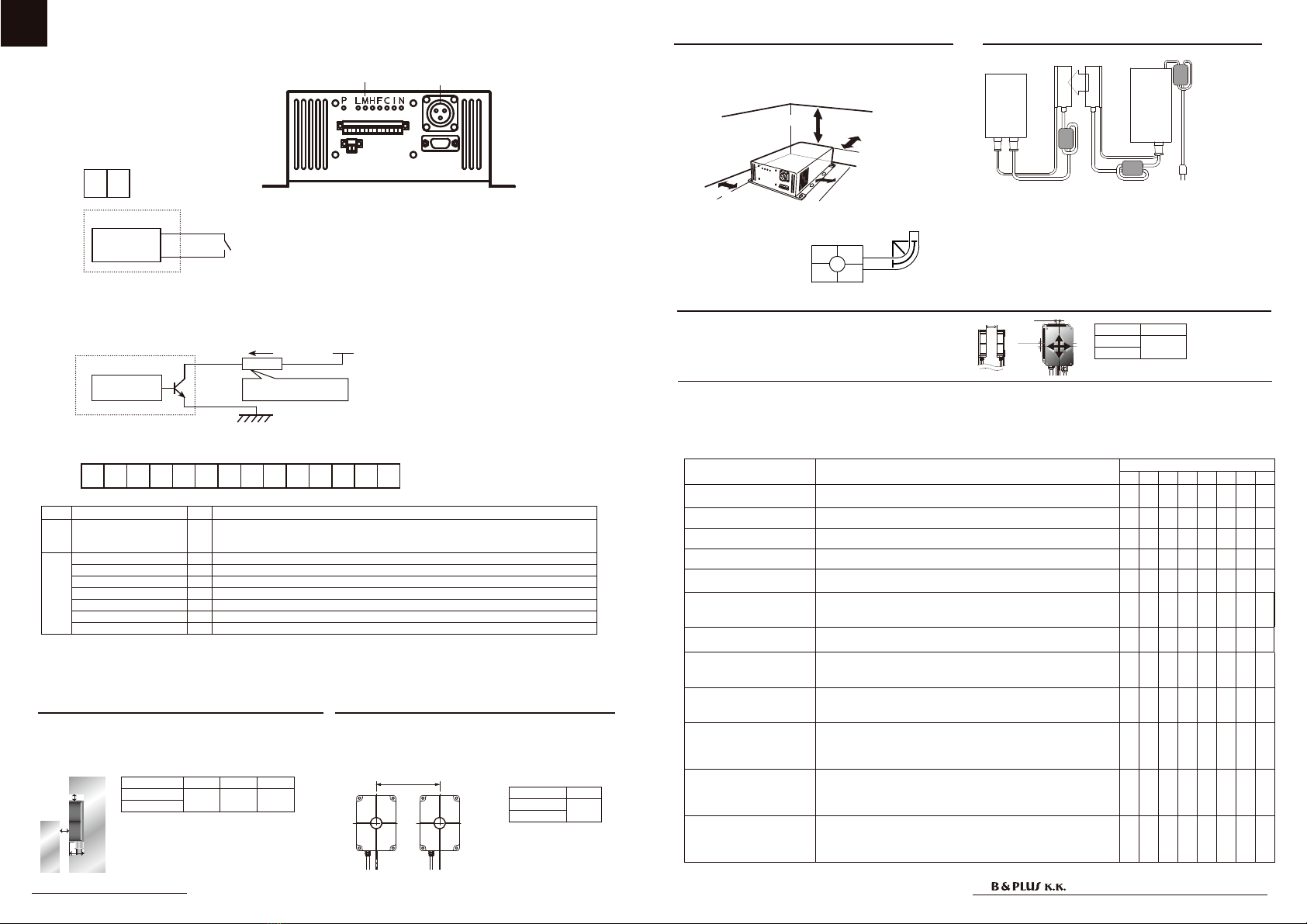
Ifyouareinstallinginparallelhead,toavoidtheeffectsof
mutualinterference,pleaseattachtheheadwithaninterval
greaterthanorequaltothevalueshowninthetablebelow
always.
Toavoidinfluenceofsurroundingmetal,keepminimumspacing.
Removemetalchipsormetallicdebrisontheactivesurface.
Metalchipsormetallicdebrisgeneratemaydamagetodevice
orcauseunexpectedtrouble.
◆ Pleasenotethatthesignalmaybecomeunstable(falsesignalorchattering)whenthetransmissiondistanceandthecenteroffset
areoutsidethespecificationrange.
◆ Theinzonesignalisapreliminarysignalforconfirmingthattheoutputsignalisestablishedwithinthespecificationrange.
Pleasenotethatitdoesnotguaranteesignalsoutputoutsidethespecificationrange.
#
Attachment
᳧᳝௨ୖ
᳧᳝௨ୖ
᳧᳝௨ୖ
᳧᳝௨ୖ
Pleasemakethefollowingisgreaterthanorequalto
thenumberofR(mm)bendingofthecableline.
・ActiveCableand
PassiveCable:R ≧ 50
・SignalCableline:R ≧ 30
PowersupplyunitandChargingunit,inordertoobtaina
goodcoolingeffect,pleasekeepasshownbelowthesepa-
rationdistancebetweenthesurroundingbodysoasnotto
blocktheairflow.
R
Centeroff-setandtransmittingdistance
Thepermissiblecenteroff-setofthefeedheadandcharging
head,pleasebeinstalledsothatthetotal(X+Y)axisdeviation
ofthewidthoftheX-axis·Y-axisisthefollowingtable.
Direction Distance
G≦ 10mm
X+Y
・Asadisplayfunction,IcanbefoundintheLEDdisplaysthestatusoftheequipment.
・Asaprotectivefunction,ithastheabilitytodetectabnormalitiessuchasoverheatingduringcharging.Inthatcase,youcanoperate
theprotectioncircuitrytoprotecttheequipment.
・Itisequippedwithacommunicationfunction,itperformsradiocommunicationwithchargingsidebetweenthepowersupplyside,we
arestatecontrolandcharging.
Thefollowingshowsthecontentsofthe<displayfunction>・<protection>.
※ Ifanabnormalityisdetected,theunitwillstopthechargingoperation.
Stateofequipment Displaycontent LED
PLMHFC I N
Intermittentoscillationstate Thisisastateinwhichpowerhavebeenturnedontothepower
unit,passiveheadisnotintheoperatingareaoftheactivehead. ●
Stateofcharge(L) Ischarging.(Chargingaim:lessthanabout50%) ●● ●●
Stateofcharge(M) Ischarging.(Chargingaim:about70%) ● ● ● ●
Stateofcharge(H) Ischarging.(Chargingaim:about90%) ● ● ● ●
Floatchargingstate Ifthechargecurrentvaluebecomesbelowaspecifiedvalue,Iwill
movetothismode. ● ●●●
Chargingvoltageerror
Batteryvoltageoutsideofadaptationhavebeenconnected,the
voltageofthebatteryisdowntoabnormal.Pleaseconnectthecor-
rectbattery.
●●●●
Batteryreverseconnectionor
non-connectionerror
Batteryterminalisturnedinreverse,cableisdisconnected.Please
checkterminal,thecable. ●● ●●
Overcurrenterror
Chargingcurrentwasincreasedabnormally.(8Aormore)Since
thereisapossibilityofequipmentfailure,youmusthaveinspection
andrepair.
●● ●●
Overvoltageerror
Chargingvoltagewasincreasedabnormally.(About33.5Vormore)
Sincethereisapossibilityofequipmentfailure,youmusthavein-
spectionandrepair.
●●● ●●
Batteryoverheating
Thebatterybecomesthespecificationtemperatureoutside.
(Specificationtemperatureis0°to40°degrees.)
Pleasereviewtheambienttemperatureenvironmentofthebattery.
Or,thermistorisdisconnected.
●● ● ●●
Inputvoltageerror
Inputvoltagefromthepassiveheadisabnormal.Pleasecheckdis-
tanceandcenteroff-setbetweentheheadsisenteringspecifica-
tionswithin.Ifyouarestillunabletoresolvetheproblem,thereisa
possibilityofequipmentfailure.
●●●● ●●
Headoverheating
Headtemperaturehasbecomeusedtothemaximumtemperature
(80℃ )ormore.Pleaseonthepoweragainaftercooling theheat.
Ifyouarestillunabletoresolvetheproblem,thereisapossibilityof
equipmentfailure.
●
2017.07.26 T313402He
● Powersupplyunitside(RCS240-AC1)
PLMHFCIN
①
②
③
⑤
④
Eachoutputsignalisopen-collector.Themaximumcurrentvalueandthemaximumoutputvoltage,pleaseconnect
soasnottoexceedthemaximumvaluebyreferringtothefollowingvalues.
Connecttheloadbeforedoingso,pleasedonotshort-circuittheoutputsignal.
PS PS
ࢩ࣮ࣙࢺ࡚ືస
P P
L+L-M+M-H+H-F+F-C+C-I+I-N+N-
12 3456 7891011121314
① Connectorfortheactivehead
② Connectorfortheactivehead
③ Start-upsignal
※ ThisistheON/OFFsignalofthepowersupplyoftheActivehead.
EithertheON/OFFswitchoperatedbyaseparate,pleaseuse
alwaysON.(Withjumper.Factory)
● Maximumloadcurrent:50mA
● Maximumloadvoltage:30V
<Inputsignalpinassignment>
Internalcircuit
Vcc
PowerSupplyunit
I
Load
Tofiteachcondition,
pleaseselecttheload
④ Variousoutputsignal
Signaltype LED Contents
Input Start-upsignal P
Shortingthissignal,performsthepowersupplytothepowerhead,powerheadstartsos-
cillating,andthenstartthecommunicationsignalandpowersupplytothepoweredhead.I
wantintermittentoscillationifthereisnoreceptionhead.
Out-
put
VoltagemonitorsignalL L
Itneedschargingforchargingamountisreduced.(Chargingaim:lessthanabout50%)
VoltagemonitorsignalM M Ifthechargehasbeenreducedsomewhat.(Chargingaim:about70%)
VoltagemonitorsignalH H Itisalmostfullycharged.(Chargingaim:about90%)
Floatchargingsignal
F Itturnson,whenachargingcurrentvalueturnsintoaratedvalue.
chargingsignal C IwillturnOFFduringchargingON,inchargecut-offandfloatchargingstart.
Inzonesignal I IwillifONisinthetransmissionareawithintheActivehead/Passivehead.
Errorsignal N Itturnson,ifabatteryerroroccurs.
⑤ LED
Function
Internalcircuit
Powersupplyunit
P
P
〇+
〇−
C
Morethan5cm
Morethan5cm Morethan10cm
Morethan5cm
GX 軸方向
Y 軸方向
X-axisdirection
Y-axis
direction
A
B
C
Metal
Metal
Mountingogtheferriteclamp
フェラ イトクラ ン プ
フェラ イトクラ ン プ
フェラ イト
クランプ
電源ユニット
充電ユニット
給電ヘッド受電ヘッド
Charging
unit
Power
Supply
unit
PassiveHead ActiveHead
ferriteclamp
ferriteclamp
ferrite
clamp
Theinstallationofthebundledferriteclampisnecessarytomeeta
standardoftheEMC(IEC61000-4-3).
Pleaseattachaferriteclamptoapowercableby2turnswiththefollowing
pointseach.
・Itisonewithin20cmfromapowersupplyunit
・Itisonewithin20cmfromapowersupplyunittothepowercableofthe
activehead.
・Itisonewithin20cmfromapassiveheadtothepowercableofthe
passivehead.
Other manuals for RCS Series
1
This manual suits for next models
4
Other B&PLUS Power Supply manuals


