9
Lighting Instructions
1. Turn main gas control arm to low.
2. Turn isolator knob to ON.
3. Wait until pilot burner lights.
4. If the pilot does not light press the flame failure reset button (Red button on main control).
5. Air will come on immediately.
6. The main burner will light automatically after about 40 seconds.
7. If there is too much air, i.e. lifting of the flame, adjust the air mixer.
8. Adjust main control arm as required.
9. Turn off by turning the isolator button to off.
10. This appliance should burn with a blue flame. If it cannot be adjusted to operate correctly or if it
burns with a long yellow flame turn the appliance of and contact the manufacturer or his approved
service agent.
In the event the appliance fails to operate correctly, check the following;
1. Data plate to ensure correct gas type and pressure (adjust if necessary)
Shutdown Procedure
1. Adjust main control arm to ‘LOW’ position.
2. Turn off by turning the isolator button to off.
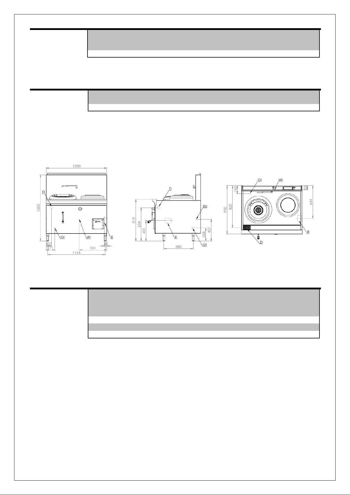
Deck Cooking (Water Spray) –Where Fitted (Water Cooled Models)
Deck cooling must be activated whenever the main stock pot burners are in use to prevent the deck of
the appliance from buckling and distorting. To activate;.
1. Locate spindle on front panel with ‘Deck’ sticker located above it.
2. Turn spindle anti-clockwise to activate water spray deck cooling. Ensure water pressure is
regulated (by turning spindle clockwise/anti-clockwise) so that only a thin layer of water remains
on the deck and trickles into the waste gutter.
3. When main burner/s is not in use ensure water is turned off by turning spindle clockwise.
Telescopic Laundry Arm –Manual Control (Water Cooled Models)
The telescopic laundry arm serves the purpose for cleaning the wok pan in between meals being cooked. Or
for filling the wok cooking pan with water to be used for cooking purposes. To activate;
1. Locate spindle on front panel with ‘Spout’ sticker located above it.
2. Turn spindle anti-clockwise to activate water from laundry arm.
3. To cease water flowing from laundry arm, turn ‘Spout’ spindle clockwise.
IMPORTANT WARNING!
NEVER LEAVE WATER RUNNING FROM TELESCOPIC LAUNDRY ARM WHILST POSITIONED
OVER THE STOCK POT SUPPORT RING WITH NO POT/PAN POSITIONED ON IT. ALWAYS MOVE
TELESCOPIC LAUNDRY ARM PARALLEL TO THE SPLASHBACK OG THE APPLIANCE WHENNOT
IN USE. DIRECT FLAME CONTACT WITH LAUNDRY ARM MAY DAMAGE OPERATION OF
LAUNDRY ARM SPOUT.
Waterset Automatic Laundry Arm (WokSpout) –Where Fitted
The WokSpout automatically shuts off the water flow when it I moved away from
the stock pot itself (as illustrated to below). It is recommended that the WokSpout
is kept parallel to the splashback of the appliance when not in use. The WokSpout
arm serves the purpose for filling the stock pot cooking pan with water to be used
for cooking purposes.
To activate, move the spout over the stock pot as required.