Bang & Olufsen Beogram CD 5500 User manual

Beogram
CD
5500
Type
5131,
5132,
5133,
5434,
5135
Beogram
CD
6500
Type
5136,
5137,
5138,
5139,
5140
Beogram
CD
7000
Type
5151,
5152,
5153,
5154,
5155
CD-Mechanism
Version
II
Beogram
CD
7000
Service
Manual
Danish,
English
BANG
&
OLUFSEN

CONTENTS
Survey
of
modules
.....
Technical
specifications
Circuit
diagrams
List
of
electrical
parts
...
List
of
mechanical
parts
Control,
Adjustments
Dismantling
Repair
hints
Insulation
test
...
Circuit
description...
Diagram,
PCB
drawing
and
partlist
for
servo
PCB30
without
focus
off-set
adjustment
......
10
Beogram
CD
5500
—
New
CD
drive
mechanism
......
Beogram
CD
6500
Beogram
CD
7000
Beogram
CD
7000
-
CD-Mechanism
Version
II
ON
AUR
WN
aa
Re}

1-2
Bang
&
Olufsen
TECHNICAL
SPECIFICATIONS
Frequency
range
3-20.000
Hz
+0.3
dB
Signal-to-noise
ratio
>100
GB/110
dB
A-weighted
Dynamic
range
>96
dB
Harmonic
distortion
incl.
noise
<0.0025%
at
0
dB
am
&
<0.025%
at
-20
dB
Channel
separation
>101
dB
Channel
difference
<0.08
dB
-
Converter
system
2
x
16
bit,
4
x
oversampling
176.4
kHz
Low
pass
filter
Digital
+
Bessel/elliptical
analog
Damping
>20.000
Hz
>50
dB
;
Phase
error
between
L
andR
0
degree
at
20-20.000
Hz
Output,
analog
1.3
V
RMS
at
0
dB
Output,
digital
For
digital
equipment
Power
supply
;
Type
no.
5131:
220
V
Type
no.
5132:
240
V
Type
no.
5133:
120
V
Type
no.
5134:
100
V
Type
no.
5135:
240
V
Power
frequency
50-60
Hz
Power
consumption
23
watts
Dimensions
W
x
H
xD
42
x
7.5
x
32.5
om
(1812"
x
3”
x
125%")
Weight
6.3
kg
(13.9
Ibs)
Subject
to
change
without
notice

2-2
2
DIAGRAM
A
(Servo
and
Disc
Motor
System)
2-2
Bang
&
Olufsen
ai
sis
Sir
3%
ex
dzadis
on
oy
ce
cls
ho
ch
i
|
—
|,
sa
Cet
teed
nme
200520:
=
3()
96
ae
04,
is
=
|
tals
pes
pas-if
Tpss-zeas-c[
pass)
Tpas-3
sv
&
|e)
8/3
A
YA
.
+
3
Bi
-9.5¥"
S{_]&
Focus
MoTOR
AMPLIFIER
ie
Hoe)
1s0n)
iol
2
[e238
in
cans
POPE,
S87
fal
&.
iehale
28
Sy
sve
-6¥a
casz]_
Ice
aes
ie
=
(4CON)
5
(8
CONICIT
CON,
Va
i
i
(200N)
2
Ce
(ae
a
7
paras
Focus:
~,
%y,
HF
OUT
JoET
j
rs
;
.
ie
a
Ai
a
:
wleaa
mee
ae
220n
S
anuieer
ues
Derecron
Ta
ed
ae)"
°
2
3k
cakeew?
ala.
Pa
aces
:
é
P3I-14
ira
FOCUS
1c6101
02
u
TOAS708
-6Va
is)
|
|
REF
8g
HEL
Sor
eps
silo
2
I
a
ons
Jes.
5
bitlpeor”
Sve
Syo~8\e
t
=
CH
LT
cain
[Sir
ampcitune
F
Se
=
Pconthou|
SLICER
HED
26D
case
ae
‘i
a
abn
2
Paine
shos
y
3 S
1
nde
pe
as
1}
ee
a
=
DenoD
RADIAL
AMPLIFIER
yo
ess
oer
Ny
%
S
rocus
+
x
ee
imieaioy
H
D3
S—|
NoRMaLions
|e
S09,
wake
rely
ue
SPSS
Creme
ee
|
l
44
Ds
ealeaa6
AMPLIFIER
IRediat
>
Ircacyy
dl,
3
=
cee
if
lo
las
470"
put
aca
a
1s
Se
(P)_S28,
mes
Denglre
oS
£
leew
4
es
at
7s,
|ezon
g
Pen
we]
|
le
aoe
:
Focus
SERVO
TASER
|
lstaitmo
fx
x
aa
rsd
Se
es
2.
3162
A259.
%
I“!
=
SUPPLY
|
|
CIRCUIT
RO.
arr
ass
Bee
Batts
uf
=
a
i
C286
=6va
+
RAD-
rei der
ton
ise
7
ss
|.
{C288
ass
|g
Be
nr
ae
TE
i
a
yt
OSCILLATOR
a
va
q
as
650
sna]
©
EG
Sk’
o
Ree
¥
Be
Ae
ig]
=e
Sa
oehs
Ko
a
ae
7
rf
pale
%
"
x
+
short
3p
Se
3
.
INTERGRATING
fe
R
2Ble
5lesles,
|
:
4
ala
sha,
AMPLIFIER
Tiasitfoaghio
so”
Rast
Ps
BEY
Risa
rRSI08
Tes
Ey
Dac
a
LASER
CURRENT
y
ac
3a
Rodiat
b
eee
ADJUSTMENT
hey
=H
ek
.
aos
iP
D4
C2160
DEMOD.
ve<
x
[Bliss
+
fo]
2
aca
RADIAL
SERVO
Bae
wourror
If
20
ARE!
sd
icy
5
Tor
sto9
ve
osl_ool_
od
Eee
c7so{
cass
A
wv
CPOE
CTI
Tog
CONNECTOR
cB
11
Benes
Sssaese
22094)
te
-8va
Tow
seRvO
PCas
MARKED
sepca
|
°
HF
1
=
px
'
c780=2n7
be
i
chsraaat
'
8
03
1 }
ae
-o5vasos
|
@
[us
o
' \
alg
fszox}-+
$
Ee
H
1
gyn
2
Focus
woror
{7
ie
'
ecard
:
disc
raciasworor
(~
GAMES
ams
.
i
-
'
508
.
**\
Rapiac
MoTOR
ry
a
ssv
ro
=
2
ah
tes
ascnoon
5
2
q|
—
AMPLIFIER:
gl
=
-
+)
rocus
woton
th
2
wane
oz
L
1
ny
03
5
a
u
oe
Pr
4
HF
L
gy
7
MOTOR
cols.
(X
CON)
"NUMBER
OF
VOLTAGE
en-20
CONNECTIONS.
27-31
9.5
(3CON)
cz0asTi00n

Bang
&Olufsen
DIAGRAMFORKLARING
Pa
diagrammet
er
der
angivet
typenumre
pa
transi-
storer
og
IC’er
i
de
tilfeelde
hvor
typenummeret
er
entydigt
for
komponentens
placering
i
kredslobet
—
feks.
TR20/BC
557B
Hvis
positionsnummeret
er
efterfulgt
af
en
stjerne
skal
reservedelsnummeret
benyttes,
da
denne
komponent
er
specielt
udvalgt
-
feks.
TR102*.
Ledningsforbindelser
Ledningsforbindelserne
pa
diagrammet
er
samlet
i
»bundter«,
De
enkelte
ledninger
er
forsynet
med
koder,
der
fortzeller
hvortil
de
gar.
INTERN
FORBINDELSE
PA
EN
DIAGRAMSIDE
Interne
forbindelser
pa
en
diagramside
angives
med
et
tal.
Knaekket
pa
ledningen
viser
i
hvilken
retning
den
anden
ende
af
ledningen
findes.
FORBINDELSE
TIL
EN
ANDEN
DIAGRAMSIDE
DIAGRAM
A
|
i
a
32
Een
Cees
Forbindelsen
til
en
anden
diagramside
angives
med
et
tal,
samt
bogstav
indikation
pa
det
diagram
forbin-
delsen
gar
til.
Forsyningsspeendinger
En
pil
og
spendingen
viser,
hvor
forsyningsspendin-
gerne
gar
ind
i
et
print.
Eksempel:
Ved
siden
af
forsyningsspendingen
star
fieks.
7
CON.
Det
betyder
at
denne
pil,
og
dermed
forsyning
gar
til
7
steder
pa
denne
diagramside
(7
CON.
=
7
connections).
Symbol
for
sikkerhedskomponenter
2-1
2-1
EXPLANATION
OF
DIAGRAM
Type
numbers
of
transistors
and
IC’s
have
been
indi-
cated
on
the
diagram
in
those
cases
where
the
type
number
is
unambiguous
for
the
position
of
the
component
in
a
circuitry
~
eg.
TR20/BC
557B.
If
the
position
number
is
followed
by
an
asterisk
the
spare
part
number
must
be
used
because
this
component
has
been
expecially
selected
-
e.g.
TR102*.
Wiring
Connections
The
wiring
connections
on
the
diagram
are
assembled
in
“bundles”.
The
individual
wires
are
coded
to
indicate
to
where
they
are
leading.
INTERNAL
CONNECTION
ON
ONE
DIAGRAM
PAGE
Internal
connections
on
a
diagram
page
are
indicated
by
a
number.
The
bend
of
the
wire
indicates
in
which
direction
the
other
end
of
the
wire
may
be
found.
CONNECTION
TO
ANOTHER
DIAGRAM
PAGE
DIAGRAM
C
l
A32
AB
pores
Dee
an
Connections
to
another
diagram
page
are
indicated
by
a
number,
as
well
as
by
a
letter
of
the
diagram
to
which
the
connections
lead.
Supply
Voltage
An
arrow
and
the
voltage
show
where
the
supply
voltages
are
fed
to
a
PCB.
Example:
Next
to
the
supply
voltage
it
says
eg.
a
CON.
This
means
that
this
arrow,
and
thus
the
supply
goes
to
7
different
places
on
this
diagram
pages
(7
CON.
=
7
connections).
Symbol
for
Safety
Components
AN
Ved
udskiftning
af
komponenter
med
dette
symbol
skal
der
anvendes
komponenter
med
samme
reserve-
delsnummer.
Den
nye
komponent
skal
monteres
pa
samme
made
som
den
udskiftede.
When
replacing
components
with
this
symbol
compo-
nents
with
identical
part
numbers
are
to
be
used.
The
new
component
must
be
fitted
in
the
same
way
as
the
one
replaced.
:

2-4
2-4
2-4
Bang
&
Olufsen
DIAGRAM
B
(Decoder)
i
soosz20
am
OB
oe
SE
o5v
EON.
4
\
1
eons
|
ce
ie
{
1
(15CON)
j
co
cay
1
acona
ws
15v
I
(cond
gs
15V
L
(5
CON.)
ge sv
ST
i
F
coN)
1
6-7
Lee,
Bt
83
MAB
8451
az
2°66
112
PES
ee
Pe
=
—
€
=
H
AIS
¢
P6=10
€
A20_—
P6-2
t
€
Azt_g
P6-3
=k
AZ?
Pee
sy
aC
5478
csi
cly*
_|cez
220p_cs[22n]
te
-_
aya
et
cane
163)
CBE
yo
;
a
4m
D
10)
659°
"foo
24
[be
foe
fob
*¥
lets”
[cte"
|cer
sy
ier
0%
4
SAA
7210
EA
DECODER
zl
RIGHT
CURRENT
OIVIOER
24
26
rh
uces
ies
ce
ATSB
€
ee
6
aT
active
10
BIT
PASSIVE
A
7220
28h
5
*
:
78
25-18
Puen
T=,
o|
SG
w
1
gp
bone
fp
[Rant
oF
switenes
sors
wt
Host”
os
P84
gsharo
PnoceSsent
RGHY
SmIFT
REGISTER
LATCH
LASTS
HET
RBTER
LARCH
|
a
fon
=
4
Ic
28¢26764
aig
ers
FST
ing
28
Le.
4
q
ahoaa
8
0
roo,
AA
FS
foa2
fata
|
foewon
||
|
[etsut
tol,
ferme
rm
g
<
TOA
1841
cso.
Se]
24h
re
su
fining
HpAFOURTEEN(”ycoRREcTOR
&
[Y
.
IcHannet|
1
zhevock
|
Dac
-
Se
SE]
hee
sco
pemoD
|
foescRawaeR
TY]
z
hrm
5
Eoraewr
]
|
2th
Sata
or
SAMPLE
5
PLEXER
|“)
Es
irererence)
|
S/]/
cay
tT
inter
2
|
fener
3
=
source
|
|
3]
58
D3
—
27)
SEFM
POLATOR|
=
JoeMuL-
coe
tp
23S
REF_|VCO
&
PHASE
JOEMUL
Lock
Loor
a)
scx
TiPLExeR|
[Nba
eal
MY
FOTEE
=
RAM
IN"
CE
2]
|
TERFA
=
ala
:
y
=
ay
Ee
EOE
ea
8
exuF
oe
LEFT
SHIFT
REGISTER/LATCH
sor
|
28
gure
[leon
Pan
1
s
sis
le
Lelia
belie
lo dy
Is
bode
Is
hs
fur
INTER:
Diora
PG
a
a
co
;
ks
Io
[gE
AA
22
Aa
Me By
As Ay
OF
Or
05
aaa
TEFT
CURRENT
BIVIDER
&
Cin
a
z
(oscucaToR]
6 BIT
ACTIVE
wart
passive
|
[s
Se)
|g
1c8_uPO
«1416
c-20
acs47a
18h-vez
TRG
=
23162y
“15y
056.
3
DINU
ma
Kk
oa
se
sol
i
BF
4sOy
R172
oe,
18)
v
Th
Se
7 ¥
3
om
coafes
Lces
|
68
|
cy
c7s|_cr7|
7
|
cox
E
ES
54
104
cs3
|
og
47n.
ne
83}
Bu
Bt] ac]
at] Bt]
Be
‘80
4p
Uap
*
7x
720n
;
—
28
28
(X
CON.)
=NUMBER
OF
VOLTAGE
CONNECTIONS

Bang
&Olufsen
SERVO
PCB
30
FOCUS
RADIAL
MoTOR
MOTOR
22372
DISC
MOTOR
CONTROL
7
2-3
SERVO
PCB
30
iz
2
ans.
ax
Peay
.
ey
4
f
(Fa
Hy
py
sats
gol
inte
Ean
~6laDe
DI
oe
1
Hcy
RADIAL
FOCUS
MoTOR MOTOR
42
234012
Ig
7
z
]
DISC
MOTOR
CONTROL

Bang
&
Olufsen
DIAGRAM
C
(Power
Supply,
Control
and
Display)
Q
mrcosies
Gam
soos
13V
ST
(2CON)
5V
ST
(SCON)
cry
38
P52
Li
a
a
o2s
a
ris
SAlTR20
oY
sv
sib
(10H-(f,
Jeceire
ast
sR
By0
ps5
care
yo
rove
—_-
—________»-svsr
(cow.
12v
st
(CON)
co
c2
Ds
c2
cr
(X
CON.)=NUMBER
OF
VOLTAGE
CONNECTIONS
z
=
5
&
a
¢
a
4228
Shower
atv0FF
1c4*
saa
oot
sv
ste
ee
3]
a
ie
3
3
z
Pe
cred
es
|
ee
2
iw
SER.DATA
RE
o
34
BIT
34
08}
Eta
arehies
.
Alster]
[Rensith
ee,
wi
5¢50
Be
rife
fret
j
t
1
reserL_t
ios
fio
1
ea
er
—_
[
101
umm
PLAY
2
]
9081
5Y
Ste.
(4CON.)
Lt
ee
58
22k}
—p—
13
St.
MUTE
TRAY
SPEED
“@
Sv
ST.
ans
TRAY
SWITCH
13
St
TR2S,
36
033

2-6
26
26
Bang
&
Olufsen
BLOCK
DIAGRAM
-
ANALOGFILTER
PCB
OS
|
6
408
UpDLIIE
©
ial
yo
9
oh
L's
BY 16
109
SA
7200
45-15,20b
mere
1610.
708.1801
aata.ciack
INTERPOLATOR
An
sang
-
OIA
CONVERTER
WS:EFLAG
IGT
TAL
FILTER
Sage
2
C6
MAB
baht
<
RST)
SERVO
uP
:
Z
:
|
x
a
sv
PCB
01°
{
DISPLAY.
DRIVE
/
TCI
Mt
S450
are
{
|
ICb
MAB
8667
:
cat
+8V
ST.
i
1
1
i
15
Te
“BV
=
POWER
13
STAND
BY
SUPPLY
12¥
STAND
BY
5
+5V
STAND
BY
+5
++
95V
SERVO
-95V
SERVO
“6v
POWER
OWOF

Bang
&
Olufsen
«Be
LIST
OF
ELECTRICAL
PARTS
In
the
player
chip
components
have
been
applied.
For
insertion
and
removal
of
chip
components
see
the
figure
below.
GENERAL
SCALE!
1
CHIP
COMPONENT
wer
7
Coreen
TRACK
=P
ce
SOLDER,
SOLDER
DISMOUNTING.
VACUUM
PISTON
SOLDERING
‘e
OUDeRINGS
eS
a
eg
WELLER
cae
ah,
SOLDER
TIP
PT-H
oR
SOLDERING
iON
\
SOLDER
WICK
sm,
\\,
2g
APAIR-OF
TWEEZERS
ff
i
MOUNTING
e.g.
A
PAIR
OF
TWEEZERS
ff:
os
iy
|
H
|
J
>
PAPER
WHIT
GLUE-DOTS
HOLD
THE
COMPONENT,
USING
@.9.
TWEEZERS.
PRESS
THE
MOUNTING
SURFACE
OF
THE
COMPONENT
AGAINST
ONE
OF
THE
GLUE
OOTS
ON
THE
PAPER
PRESS
THE
COMPONENT
AGAINST
!TS
PLACE
OF
MOUNTING,
THE
COMPONENT
IS
NOW
SLUED
TO
THE
MOUTING
PLACE,
AND
CAN
BE
SOLDERED.
eg
APAIR
OF
TWEEZERS
4)
up
:
SOLDER
OS-
08mm
sovoering
S
RON
PON
INS
SOLDERING
TIME
SOLDER
c
J
sec
sie
05-08
mm
/
SOLDERING
s
IRON
PRECAUTIONS
SOLDERING
ISOLDERING
IRON
IRON
CHIP.
COMPONENT
COPPER
TAACK
FOR THE
SAKE
OF
THE
SOLDERING
ABILITY.
AFTER
STORAGE,
THE
COMPONENT
SHCULD
NOT
BE
TOUCHED
WITH
THE
HANDS.
4
eee
ee
ee
EXAMPLES
Cc
a
|
i)
RIGHT
P,
SOLDERING

3-2
Standard
resistors:
Resistors
SMD
5%
1/8
W
Resistors
5%
1/2
W
Resistors
5%
1/4
W
Resistors
5%
1/8
W
Bang
&
Olufsen
Resisiors
not
mentioned
are
standard
resistor.
XL
x10
_|"xtoo
|
XiK
XI0K_|
X100K
XIM
X10M
10
|
5011333
|
5011295
12
5011296
is
5011203
5011274
{5011197
|
5011272
5011299
|
5011273
|
5011310
5011205
|
5011306
|
5011189
5011207
5011195,
5011198
5011320
|
5011332
5011321
5011322
18
5011297
2.2
15011282
|
5011192
2.7
|
5013283
|
5011275
5011300
|
5011286
}
5011311
5011194
|
5011307
|
5011312
5011301
|
5011183
|
5011271
5011196
5011208
5011316
5011323
5011324
5012325
3.3
15012289
|
5011202
3.9
|5011290
)5011298
4.7
|
5011291
|
5011191
5011188
|
5011184
|
5011313
5011302
|
5011308
|
5011314
5011303
|
5011193
|
5011284
5011520
1
5011317
5011318
5011206
5011436
5011326
5.6
}5011292
|
5011276
68
|
5011293
|
5011190
82
|5011294
|
5011185
5011304
|
5011309
|
5011199
5011305
|
5011186
|
5011200
5011187
[5011285
[5011315
5011288.
§011319
5011201
XL
X10
X100
X1K
X1OK
X100K
X1M_|
X10M
5010857
2.2
|
5011335
|
5
5010803
5011013
|
5011028
|
5011044
5011014
|
5011030
|
5011045,
5011015
|
5011031
|
5011046
5011016
|
5011033
|
5011047
5010815
|
5011034
|
5011048
5011018
|
5010055
|
5011049
3.3
|
5010255
|
5011007
39
5010782
5010765
|
5013009
5011010
5011019
|
5011037
5011021
}
5010700
|
5011051
5011022
|
5010035
|
5010036
5011042
|
5010810
5011026
3
15010038,
5010313
5012058
5011059
5011061
5011062
5011063
5011065
5011066
5011067
5011068
8
|
5010874
|
5011011
82
5011012
|
5010040
5010153
5010247
|
5010053
5010066
|
5010135
5010064
|
5010079
5010059
5010046
5010362
5010092
5010000
5010298
|
5010141
|
5010083
5010049
5010047
5010063
5010072
5010120
5010411
5010151
5010706
5010044
|
5010076
|
5010075
5010070
|
5010069
|
5010060
5010048
|
5010045
5010041
|
5010061
5010067
5010117
5010073
5010077
5010071
5011069
|
5011083
5010421
5011071
5011072
5011074
5011075
5010381
5010392
5011078
5011079
5011080
5011081
5010054
5010665
5010093
$010791
5010245
5010431
5010848
5010714
5011513
5010658
5010638
68
5010904
|
5010039
|
5010144
|
5010052
}
5010062
|
5010074
8.2
|
5010880
|
5010056
|
5010068
|
5010154
|
5010091
|
5010505
(7
X10
_[_X100
|
XiK
|
X10K
[X100K]
X1M
16
5011464
|
5011357
|
5010816
}
5010935
|
5011440
|
5011459
|
5020875
12
5011351
|
5011084
|
5011442
|
5011338
|
5011341
|
5011175
15
5011463
|
5011443
|
5011178
)
5011364
|
5011398
|
5011460
18
5011350
|
5011361
|
5011344
|
5011468
2.2
|
5011032
|
5011376
|
5010886
|
5011353
|
5010833
|
5011369
|
5011342
27
5011471
|
5011355
|
5011362
|
5011366
|
5011370
|
5011478
33
5011337
|
5010827
|
5011346
|
5011371
|
5011462
39
5011438
5011157
|
5011457
|
5011372
|
5020876
47
5011363
|
5011038
5011441
|
5011363
|
5010937
|
5011343
56
5011412
|
5011358
|
5010885
|
5011166
|
5011340
68
5011356
|
5011336
|
5010839
|
5011367
|
5011458
82
_}
5011466
|
5011354
5011339
|
5011368
|
5011373

Bang
&
Olufsen
3-3
|
23
|
24
[
31
[32
|
44
|
49
|
si
¢
BI
5
©
(ec
if
®
||)
4D)
oO
x
a)
Mur,
PCB
1,
8005217
IClO
8340467
124
MM
S450N
Display
D1-
8300023
209
1N
4002
D3-
8330150
246
LED
red
D2
D26
RI
5370068
22
kQ
20%
0.1W
C2
4010105
1
nF
10%
63V
3
4130230
100
nF
20%
63V
Sl
7400268
contact
1
pol
Pll
——-7220580
Plug
2
pol
To
P7
6275711
Wire
w/sockets
7/7
pin
PCB
2,
8005218
$101
7400268
contact
1
pol
Contact
PCB
To
Pll
6275712
Wire
w/sockets
2/2
pin
PCB
5,
8005220
Ic1-
8340065
105
7805
PWR
supl.
+5 1A
Decoder
1c2
Ic3
8340931
123
7906
PWR
supl.
-6V
1A
IC44
8340957
125
MAB
8461
ICS
8340157
102
LM
324
IC6A
8340914
136
MAB
8441
pC
IC7A
8340841
136
SAA
7210
Decoder
IC8A
8340927
111
UPD
41416
C
IC9A
——-
8340855
136
SAA
7220
Digital
filter
IC10A
8340913
136
TDA
1541
D/A
Converter
IC1i-
8340930
103
LM
833N
DUAL
OP-AMP
IC12
TRI
8320640
17
BC
636
TR27
8320152
20.
BC
557B
TR2
8320097
20
BC
547B
TR28-
8320427
32
BD
437
TR3
TR29
TRS
8320542
44
BD
825-16
TR30-
8320097
20
BC
547B
TR6-
8320152
20 BC
557B
TR32
TR?
TR33.
8320152
20
BC
557B
TR10*
8320369
31
BD
534
TR34.
8220427
32
BD
437
TR1-
8320097
20 BC
547B
TR35,
TR12
TR38-
8320097
20
BC
647B
TRi3-
8320152
20 BC
557B
TR39
Pees
ome
TRI
TR42
8320097
20 BC
5478
“TRIS”
832054244
BD
825-16
~~
TR4S-“""8320152
20°
BO'SS7B
TR16
8320152
20
BC
557B
TR44
83205367
23 BF
450
TR20
8320097
20
BC
547B
TR45
8320097
20 BC
547B
TR21
8320152
20
BC
557B
TR48
8320097
20 BC
547B
‘TR24-
8320097
20
BC
5478
TR49
8320152
20 BC
557B
TR26
TRIO1
8320722
24
2N
5638

3-4
eve
)
Bang
&Olufsen
TR102-
8320660
49
2SC
2878A
TR202-
8320660
49
2SC
2878A
TR103
TR203
TR20i
8320722
24
2N
5638
Di-
8300023
209
1N
4002
D18
8300023
209
1N
4002
D4
D19
8300479
209
ZPD
79B
5.1V
DS
8300407
209
ZPD
12V
D20-
8300023
209
1N
4002
D6
8300578
209 BZX
79
B9V1
D21
BZX
55
BOV}
D22-
8300222
209
ZPD
2.7
V
D7
8300058
209
1N
4148
D23
Ds
8300578
209
BZX
79
B9V1
D25
8300407
209
ZPD
12
V
BZX
55
B9VL
D26-
8300058
209
1N
4148
Dg
8300058
209
1N
4148
D27
DLO
8300142
209
AA
143
D31-
8300058
209
1N
4148
Dil-
8300294
212
1N
5401
D35
Did
B40
8300058
209
1N
4148
D1i5
8300023
209
iN
4002
D42
8300596
209
6.2V
2%
D16-
8300579
209
BZX
79
B10OV
D43
8300058
209
IN
4148
Di7
BZX
55
B10V
RS
5020110
10
kQ
1%
1/4W
R118
5011511
2.1
kQ
1%
1/4W
R6
5020318
13
kQ
1%
1/4W
R119
5011512
750
Q
1%
1/4W
R1l-
5020499
0.1
Q
10%
o4W
R126
5020956
68
Q
5%
0.14W
R12
R150
55030001
8
x
22
kQ 5%
1/8W
RIS
5020110
10
kQ
1%
1/4W
R171
5011512
750Q
1%
1/4w
RIG
5020318
13
kQ
1%
1/4W
R172
5021011
1.87
kQ
1%
1/4W
R57
5020542
22.1
kQ
1%
V/4W
R173
5020730
5.90
kQ
1%
1/4W
R58
5020362
56.2
kO
1%
1/4W
R174
5011508
200
Q
1%
1/4W
R6O
5010862
7
x
4.7
kQ
5%
1/8W
R212
5011507
374
Q
1%
1/4W
RVE
5020980
0.82
Q
5%
1W
R214
5011508
200
Q
1%
1/4W
R86
5020980
0.82
Q
5%
1W
R2i5-
5011509
15
kQ
1%
V/4W
R101
5020956
68
O
5%
0.14W
R216
R112
5011507
374
Q
1%
1/4W
R217
5011510
1
kQ 1%
1/4W
R114
5011508
200
Q
1%
1/4W
R218
5011511
2.1
kQ
1%
1/4W
R115-
5011509
1.5
kQ
1%
1/4W
R219
5011512
750
Q
1%
1/4W
R116 R226
5020956
68
Q
5%
0.14W
R17
5011510
1
kQ
1%
1/4W
4000340
22
nF
-20+80%
40V
4200102
470
pF
-10+100%
40V
4130308
220
UF
10%
63V
4200102
470
UF
-10+100%
40V
4130308
220
nF
10%
63V
4200524
10
uF
20%
25V
4200020
4700
pF
25V
4130309
330
nF
10%
63V
4200544
22
uF
20%
16V
4200548
2200
uF
-10+50%
25V
4200517
2.2
pF
20%
50V
4200512
1
uF
20% 50V
4030035
1
nF
10%
63V
4000339
33
pF
5%
63V
4010035
1
nF
10%
63V
4000339
33
pF
5%
63V
4010035
1
nF
10%
63V
4200625
3.3
pF
20%
50V
..
4200617
47
pF
20%
10V.
4010107
22
nF
-20+80%
40V
4000204
100
pF
5%
63V
4010035
inF
10% 63V
4200625
3.3
pF
20%
50
4000340
22
nF
-20+80%
40¥
C48.
4200617
47
LF
20%
10V
C49.
4000339
33
pF
5%
63V
C52
4200625
3.3
pF
20%
50V
C53.
4000340
22
nF
-20+80%
40V.
C54
4200617
47
UF
20%
10V
CSS
4100195
1.8
nF
5%
63V.
C56
4000137
47
pF
5%
63V.
CS7
4200512
1
uF
20%
50V
C58
4130240
47
nF
10%
63V
C59
4000340
22
nF
-20+80%
40V
C60
4200617
47
uF
20%
10V
C61
4200122
220
uF
-10+100%
10V
C62
4000340
22
nF
-20+80%
40V
C65
4000340
22
nF
-20+80%
40V
C66
4200617
47
pF
20%
10V
C67-
4000137
47
pF
5%
63V
c71-
4130208
220
nF
10%
63V
C78
4000340
22
nF
-20+80%
40V
c79
4200617
47
pF
20%
10V
Cao
4010122
680
pF
10%
63V
C81-
4130308.
220
nF
10%
63V___
Cas
4130240
47
nF
10%
63V
cas
4200688
47
pF
20%
50V
coo
4200617
47
pF
20%
10V
C91
4130240
47
nF
10% 63V

Bang
&
Olufsen
PCB
6,
8005221
Motor
PCB
7,
8005219
Optocoupler
PCB
8,
8005169
Mains
Transformer
PCB
9,
8005223
Socket
panel
PCB
10,
8005223
Din
socket
PCB
11,
8005222
PCB
f.
Flex
Print
“PCB
36,
8005204
~~
Servo
3-5
92
4000340
22
nF
-2080%
40V
C110
4200403
100
pF
-10+100%
25V
€93-
4130235
47
nF
20%
63V
C111
4200480
22
pF
20%
10V
Co4
C202
4200403
100
uF
-10+100%
25V
C95.
4130210
47
nF
20%
63
C203
4130267
18
nF
5%
63V
C98
C204
4130270
68
nF
5%
63V
C99
4200512
1
uF
20%
50V
C205
4100278
8.2
nF
2.5%
63V
C102
4200403
100
pF
-16+100%
25V
C206-
4100249
680
pF
2.5%
63V
C103
4130267
18
nF
5%
63V
207
C204
4130270
68
nF
5%
63V
C208
4100230
1.5
nF
2.5%
63V
C105
4100278
8.2
nF
2.5%
63V
C209
4100279
2
nF
2.5%
63V
C106-
4100249
680
pF
2.5%
63
C210
4200403
100
pF
1/4
10+100%
C107
25V
C108
4100230
15
nF
2.5%
63V
C211
4200480
22
pF
20%
10¥
C109
4100279
2
nF
2.5%
63V
Li-
8020565
2.2
pH
13
8020639
100
pH
Le
X1-
8090009
6.0
MHz
X3
8090058
11.2896
MHz
x2
P2
7220574
Plug
3
pol
PG
7220582
Plug
14
pol
P3
7220312
Plug
2
pol
P7
7220471
Plug
7
pol
Pa
7220313
Plug
3
pol
P8
7220312
Plug
2
pol
P5
7220583
Plug
5
pol
P10
7220584
Plug
8
pol
a
4010107
22
nF
-20-80%
40V
To
P3
6275715
Wire
w/sockets
2/2
pin
To
P2
6275744
Wire
w/sokets
3/3
pin
PE201
8330196
Optocupler
PI
7220584
Plug
8
pol
TF1
6609029
Thermal
fuse
130°
C
6275755
Audio
wire
bundle
Cl-
4010103
2.2
nF
10%
637
3
4010128
470
pF
10%
63V
C2
7210384
Phono
Socket
(female)
7210600
DIN
socket
(female)
7
pol
P12
7210614
Socket
14
pol.
Pi3
C6101
8340991
125
TDA
5708
C3
16102
8340992
134
TDA
5769
~~
7C6103~
8340993"
103"
NIM
4560D
1C6104
8340683
103
L
272BH
‘TR6108
8320721
020
BC
338-16
TR6109
8320615
051
BC
848B
TR6112
$320616
051
BC
858B

Bang
&Olufsen
D6107
8300058
209
1N
4148
D6118-
8300570
209
HZ
7C2 7V5
D6110-
8300058
209
1N
4148
D6119
D6111L
R3101
5020966
12
Q
5%
1/3W
R3151
5011254
82
kQ
2%
1/8W
R3102
5011234
4.7
kQ
2%
1/8W
R3152
5011314
39
kQ
5%
1/8W
R3103
5011256
100
kQ
2%
1/8W
R3154
5021491
39
kQ
2%
1/8W
R3104
5020967
18
Q
5%
1/3W
R3155
5011241
10
kQ
2%
1/8W
R3105
5011218
100
Q
2%
1/8W
R3156-
5011245
22
kQ 2%
1/8W
R3106
5370355
1kQ
20%
R3157
R3107-
5020965
4.7
Q
2%
1/3W
R3158
5011233
39
kQ
2%
1/8W
R308
R3159
5010547
18
kQ
2%
1/4W
R3109
5011244
18
kQ
2%
1/8W
R3160
5020971
4.7
Q
1%
1/4W
R3110
5011490
12
kQ
2%
1/8W
R3161
5011490
12
kQ
2%
1/8W
R3111
5011230
2.2
kQ
2%
1/8W
R3162
5011254
82
kQ
2%
SW
R3112
5011267
1
mQ
2%
1/SW
R3163
5010056
82
Q
5%
1/4W
R3113_
5011218
100
Q
2%
1/8W
R3166
5011250
47
kQ
2%
1/8W
R3114
5011238
6.8
kQ 2%
1/8W
R3167
5011490
12
kQ
2%
1/8W
:
R3115
5011319
680
kQ 5%
1/8W
R3191
5011241
10
kO
2%
1/8W
—
H
R3116
5011218
100
Q
2%
1/8W
R3192-
5011245
22
kQ
2%
1/8W
*
|
R3135
5011586
11
kQ
2%
1/8W
R3193
4
R3136
5011259
150
kQ
2%
1/8W
R3201
5011254
82
kQ
2%
1/8W
R3137
5011257
120
kQ
2%
1/8W
R3202
5011250
47
kQ
2%
1/8W
R3138
5020964
1.0
Q
2%
1/3W
R3204
3011238
6.8
kQ
2%
1/3W
R3139
5011254
82
kQ
2%
1/8W
R3205
5011254
82
kQ
2%
1/8W
R3140
5020964
1.0
Q
2%
1/3W
R3206
5011255
91
kQ
2%
1/8W
R3141
5011587
160
kQ
2%
R3207
5020263
100
kQ 1%
1/4W
R3143
5011269
47
Q
2%
1/8W
R3208
5020969
47
kQ
1%
1/4W
R3144
5011255
91
kQ
2%
SW
R3209
5011234
4.7
kQ
2%
1/8W
“)
R3145
5011318
390
kQ
5%
1/8W
R3210-
5020964
10
Q
2%
1/3W
R3146
5370254
22
kQ
20%
o.1W
R3211
R3150
5011491
39
kQ
2%
1/8W
C2101
4000255
22
nF
10%
SOV
C2139
4000255
22
nF
10%
50V.
C2102
4000249
470
pF
5%
SOV
C2140
4200745
220
mF
16V
C2103
4200414
33
mF-10+50%
16V
C2141
4130245
220
nF
5%
63V.
C2104
4200482
47
mF
20%
10V
C2142
4000256
100
nf
10%
50V
C2105-
4000255
22
nF
10% SOV
C2150-
4130424
3.6
aF
160V
1%
C2106
C2151
C2107
4200482
47
mF
20%
10V
C2152
4130206
220
nF
10%
100V
C2108
4000254
10
nF
10%
50V
C2153.
4130314
180
nF
10%
63V
C2109
4130379
270
nF
5%
63V
C2154
4130206
220
nF
10%
100V
C2110
4000253
5.6
nF
10%
50V
C2155
4130405
470
nF
10%
50V
C2111
4130405
470
nF
10%
SOV
C2156
4130338
6.8
nF
5%
100V
C2112
4130406
150
nF
5%
SOV
C2159
4130293
470
nF
10%
63V.
C2113
4000248
100
pF
5%
SOV
C2160
4010173
4.7
nF
10%
50V
C2114
4000233
220
pF
5%
50V
C2200
©
4010173
4.7
nF
10%
50V
C2117
4010172
4.7
nF
10%
50V.
C2202
4130405
470
nF
10%
50V.
C2135
4130370
4,7
nF
5%
C2203
4130221
18
nF
5%
63V.
C2136
4130405
470
nF
10%
SOV
C2204-
4000255
22
nF
10%
SOV
C2137
4000255
22
nF
10%
50V
C2205
C2138
4200745
220
mF
16V
P31
7210614
Socket
i4
pol
P34
7220657
Plug
14
pol
P33:
7220652
Plug
5
pol
P36
7220651
Plug
4
pol
To
P5
6275746
Wire
w/sokets
To
P6
6275745
Wire
w/sokets
5/5
pin
M/4
pin
A
betyder
at
statisk
elektricitet
kan
edelagge
komponenten.
A
indicates
that
static
electricity
may
destroy
the
component.
A
bedeutet,
da
statische
Elektrizitat
die
Komponente
zerstéren
kann.
Sa
ae
aT
A
signifi
que
électricité
statique
peut
detruire
Je
composant
*
Speciel
udvaigt
eller
bearbejdet
eksemplar.
*
Specially
selected
or
adapted
sample.
*
Speziell
ausgewahltes
und
bearbeitets
Exemplar.
*
Exemplaire,
spécialement
sélectionné
et
faconne.

Bang
&
Olufsen
4-1
4-1
4-1
MECHANICAL
PARTSLIST
Chassis
01Modul
8005217
Display
0101
3131247
Housing
Bargraph
3370152
Difus
Tape
Bargraph
01S1
7400268
Contact
0103
3131252
Housing
Display
3370155
Difus
Tape
display
05Modul
8005220
Decoder
0501
3358228
Heat
sink
0502
2816195
Spring
(transistor)
0503
2566047
Guide
rail
0504
2816000
Spring
(transistor)
0505
3358202
Heat
sink
9065
09Modul
8005223
PCB
socket
panel
10Modul
8005223
PCB
Din
socket
1001
7210600
Plug
7
pol.
11Modul
8005222
Print
f.
flex
print
30Modul
8005204
Servo
9046
96Modul
8420138
Mechanism
02S101
7400268
Contact
08T1
8005169
PCB
8
wTransformer
0201
8005218
PCB
0802
3152472
Holder
for
mains
cord
0801
6271102
Mains
cord
(EU)
06M1
8400169
Motor
6270251
Mains
cord
(US)
0601
2938253
Bushing
6271119
Mains
cord
(J)
0602
2930074
Bushing
6270297
Mains
cord
(AUS)
0603
8005221
PCB
90S1
7400322
Switch
07PE201
8330196
Optocoupler
0701
8005219
PCB
9001
3414032
Cabinet
9027
2622412
Washer
f.
CD
holder
9002
3034073
Bracket
9028
3356048
Magnet
9003
2391059
Bracket
9029
3152536
Holder
f.
CD
9004
2816243
Spring
9030
3454479
CD
tray
9005,
7219065
Bracket
f.
socket
panel
9031
2751020
Driving
plate
9006
3112331
Chassis
(for
PCB)
9032
2851214
Arm
9007
3152366
Wire
holder
9033
3152118
Wire
holder
9008
3454445
Bottom
9034
3150069
Holder
9009
3152101
Wire
holder
9035
3114289
Chassis
f.
CD
mech.
9010
3035119
Slide
shoe
9036
2930099
Bushing
9011
2816239
Leaf
spring
9037
2830128
Shaft
bar
short
9012
2816240
Spring
for
trolley
shoe
9038
3150068
Holder
9013
2732083
Belt
9039
2830129
Shaft
bar
long
9014
2724076
Tacho
wheel
9040
2810216
Spring
9015
2830134
Shaft
9041
2810215
Spring
9016
3010029
Stop
block
rubber
9042
3955041
Wire
9018
6141178
Flex
PCB
9043
2542698
Angle
f.
front
9019
7500176
Solder
tag
9044
3112334
Chassis
9020
2576109
Spacer
9045
2542699
Angle
9021
2724069
Cord
pulley
9046
2850141
Arm
9022
2830133
Shaft
9047
2560218
Bracket
f.
front
9023
3010007
Stop
blok
9048
3114273
Chassis
front
9024
2938253
Rubber
bushing
9049
2568978
Front
panel
9025
2905120
Seat
f.
CD
holder
9050
3152560
Transport
screw
9026
2510158
Bracket
f.
CD
holder
9051
6032258
Wire

Screws,
washers,
etc.
4-2
3603
9601
3333016
Rubber
holders
9610
9602
3152593
Clamp
f.
flexprint
9611
9603
3034077
Transport
screw
9612
9604
8330210
Focusunit
9614
9605
2917024
Ball
9615
9606
2389077
Spee.
nut
96074
3131296
Rafoc
9608
3010031
Rubber
stop
9609
6141131
Flex
print
O
Replacement
of
9604
see
page
5-5,
5-9
©
Replacement
of
9607
see
page
5-4,
5-5,
5-12
2622426
Washer
f.
foil
2917024
Ball
2905116
Pivot
plate
3333015
Rubber
holders
3342046
Weighing
block
The
disc
motor
system
pos.
no.
9613,
9616
and
9617
are
one
unit,
part
no,
3114292
1
2038097
Screw
M3x6
mm
13
2
2043016
Screw
AM
4x10
mm
14
3
2038096
Screw
M3x5
mm
20
4
2038098
Screw
M3x8
mm
21
5
2036016
Screw
AM
2.6x6
mm
22
6
2013136
Screw
3x6
mm
23
7
2013137
Screw
3x10
mm
30
8
2038103
Screw
AM
3x12
mm
40
9
2011038
Screw
2.2x10
mm
41
10
2013149
Screw
2.9x16
mm
42
e8
2038120
Screw
3x25
mm
50
12
2013094
Screw
M
2.9x6.5
mm
51
2013145
Screw
3x
12
mm
2034064
Screw
2x
10
mm
2622052
Washer
3.2x8x1
mm
2622348
Washer
2.3
mm
2622321
Washer
32
mm
2624013
Washer
3
mm
2625002
Tooth
lock
washer
3.2
2380011
Nut
M3
2380012
Nut
M3
2380147
Nut
M3
2390001
Spring
washer
2.3
DIN
2390103
Spring
washer
@2x0.25
4-2
Parts
not
shown
7500157
Crimp
f.
wire
3391251
Outer
carton
3391997
Insert
for
packing
3397571
Foam
packing,
set
3946048
Foil
6270213
Signal
cable
7
pol.
3629107
Blade
T6
short
3629037
Blade
TS
short
3629102
Blade
T10
long
3629038
Blade
T10
short
3629103
Blade
T20
short
3629109
Screw
driver
T6
3629108
Screw
driver
T8
3629047
Screw
driver
T10
Bang
&
Olufsen
3629104
Screw
driver
T20
3634030
Glass
disc
3634031
Test
disc
5
and
5A
3634032
Magnet
ring
3505479
Owner’s
Manual
DK
3505480
Owner's
Manual
S
3505481
Owner's
Manual
SF
3505482
Owner's
Manual
GB
3505483
Owner's
Manual
D
3505484
Owner's
Manual
NL
3505485
Owner’s
Manual
F
3505486
Owner's
Manual
I
3505487
Owner's
Manual
USA

Bang
&
Olufsen
MEKANISKE
JUSTERINGER
Hojde
pa
lobeverket
Justeringen
foretages
med
de
4
skruer
i
gummidem-
perne
i
hjarnerne
pa
lobevzerket
De
2
bageste
skruer
kan
justeres
gennem
hullerne
F
i
pladeskuffen
nar
skuffen
er
inde,
og
de
2
forreste
nar
skuffen
er
nzs-
ten
ude.
Der
ber
justeres
lige
meget
og
i
samme
retn-
ing
pa
alle
4
skruer.
For
at
nd
de
2
forreste
skruer
skal
den
lange
vinkel
over
fronten
tages
af,
og
for
at
Jette
justeringen
vippes
fronten
ned.
Leg
CD-plade
i
og
tryk
pladeskuffen
ind.
Juster
de
4
neevnte
skruer
til
CD-pladens
underkant
er
0,3
mm
-.0,3
mm
over
pladeskuffens
overkant
nar
pladeskuffen
er
inde.
5-1
MECHANICAL
ADJUSTMENTS
Height
of
drive
mechanism
Make
the
adjustment
with
the
4
screws
in
the
rubber
dampers
at
the
corners
of
the
drive
mechanism.
The.
2
rearmost
screws
may
be
adjusted
through
the
holes
F
in
the
disc
drawer
when
the
drawer
is
in,
and
the
2
frontmost
screws
may
be
adjusted
when
the
drawer
is
almost
out.
All
4
screws
should
be
adjusted
identi-
cally.
In
order
to
reach
the
2
frontmost
screws,
the
long
bracket
at
the
top
of
the
front
should
be
removed,
and
the
front
should
be
tilted
down
to
faci-
litate
the
adjustment.
Insert
a
CD
and
push
in
the
disc
drawer.
Adjust
the
4
screws
mentioned
until
the
lower
edge
of
the
CD
is
0.3
mm
+0.3
mm
above
the
upper
edge
of
the
dise
drawer
when
the
disc
drawer
is
in.
Centrering
af
lobevzerk
Centring
of
drive
mechanism
A
8B
C
os
Fe
O-
=O
E
D
/
.
4
=
aS
[=
Leg
en
CD-plade
i
og
tryk
pladeskuffen
ind.
Skruen
A
lesnes.
Ekscentrik
B
justeres
til
CD
pladen
er
midt
i
fordyb-
ningen
i
pladeskuffen.
en
A
spandes.
Load
a
CD
and
push
the
disc
drawer
in.
Loosen
screw
A.
Using
eccentric
B,
adjust
until
the
CD
is
at
the
centre
of
the
depression
in
the
disc
drawer.
Tighten
screw
A.

5-2
Centrering
af
vinkel
for
pladeholdermagnet
Pladeskuffen
trykkes
ind.
Skruen
A
skal
veere
losnet.
Ekscentrik
C
justeres
til
pladeholdermagneten
D
lig-
ger
midt
i
hullet
i
vinklen
E.
Skruen
A
spaendes.
Hojde
af
vinkel
for
pladeholdermagnet
Leeg
en
CD
plade
og
tryk
pladeskuffen
ind.
Right
Hand
Side
Bang
&Olufsen
Centring
of
bracket
for
disc
clamping
magnet
Push
in
the
disc
drawer.
Screw
A
must
be
loosened.
Using
eccentric
C,
adjust
until
the
disc
clamping
mag-
net
D
is
at
the
centre
of
the
hole
in
the
bracket
E.
Tighten
screw
A.
Height
of
bracket
for
disc
clamping
magnet
Insert
a
CD
and
push
in
the
disc
drawer.
Skruen
G
justeres
til
hajden
af
vinklen
E
ligger
midt
i
frigangen
H
pa
plademagneten
D.
Kontrolier
at
pladeholdermagneten
ikke
gar
imod
metalpladen,
som
er
limet
pa
den
bageste
del
af
pla-
deskuffen,
nar
skuffen
trekkes
ud
og
ind.
Stop
position
for
pladeskuffe
Pladeskuffen
skal
veere
trykket
helt
ind.
Medens
skuffen
trykkes
ind
mod
stop,
justeres
unbra-
koskruen
(5
mm)
under
bunden,
indtil
skuffeforkanten
fiugter
med
fronten
pa
apparatet.
Hoejde
pladeskuffe
forkant
Pladeskutfen
trykkes
ind.
De
2
skruer
under
den
forreste
del-af
bunden
justeres
til
overkanten
af
pladeskuffen
flugter
med
overkanten
af
aluminiumslisten
pa
fronten.
By
means
of
screw
G,
adjust
until
the
height
of
the
bracket
E
is
at
the
centre
of
the
clearance
H
between
the
bracket
and
the
disc
magnet
D.
Make
sure
that
the
disc
clamping
magnet
does
not
hit
the
metal
sheet
which
is
glued
onto
the
rearmost
part
of
the
disc
drawer
when
the
drawer
is
pulled
out
and
pushed
in.
Stop
position
for
disc
drawer
The
disc
drawer
must
be
fully
depressed.
While
the
drawer
is
pressed
against
stop,
adjust
the
allen
screw
(5
mm)
in
the
bottom
until
the
front
edge
of
the
drawer
is
flush
with
the
front
of
the
set.
Height
of
front
edge
of
disc
drawer
Push
in
the
disc
drawer.
By
means
of
the
2
screws
under
the
front
part
of
the
bottom,
adjust
until
the
upper
edge
of
the
disc
drawer
is
flush
with
the
upper
edge
of
the
aluminium
strip
on
the
front.

Bang
&
Olufsen
ELEKTRISKE
JUSTERINGER
Lysintensiiet
(Brightness)
ELECTRIC
ADJUSTMENTS
Brightness
PCB4
(Display)
4
D2
Rt
1D2
loddes
fri
og
leftes
i
den
ene
ende.
Milliamperemeter
szttes
ind
i
serie
med
1D2.
Heeg
en
CD
plade
med
mere
end
15
numre.
Tryk
PLAY.
1R1
justeres
til
der
males
153
mA
+5
mA.
+5V
stromforsyning
4
TRIO.
lag
en
CD
plade
og
tryk
PLAY.
Mal
DC
spzendingen
fra
ben
20
til
ben
40
pa
5IC7.
(SAA
7210).
NB!
Der
skal
males
direkte
pa
IC’en.
5D10
skal
vaere
kortsluttet
(5377).
Hvis
den
mialte
spending
er
lavere
end
4,85
V
skal
5J77
afbrydes.
Unsolder
1D2
and
elevate
it
at
one
end.
Connect
2
milliammeter
in
series
with 1D2.
Insert
a
CD
with
more
than
15
tracks.
Press
PLAY.
Adjust
1R1
until
a
measurement
of
153mA
+5mA
is
obtained.
+5V
power
supply
10
Load
a
CD
and
press
PLAY.
Measure
the
DC
voltage
from
pin
20
to
pin
40
of
5IC7
(SAA
7210).
NOTE:
The
measurement
must
be
made
on
the
IC
directly.
5D10
must
be
short-circuited
(5J77).
If
the
measured
voltage
is
less
than
4.85V,
5J77
has
to
be
disconnected.
This manual suits for next models
17
Table of contents
Other Bang & Olufsen CD Player manuals
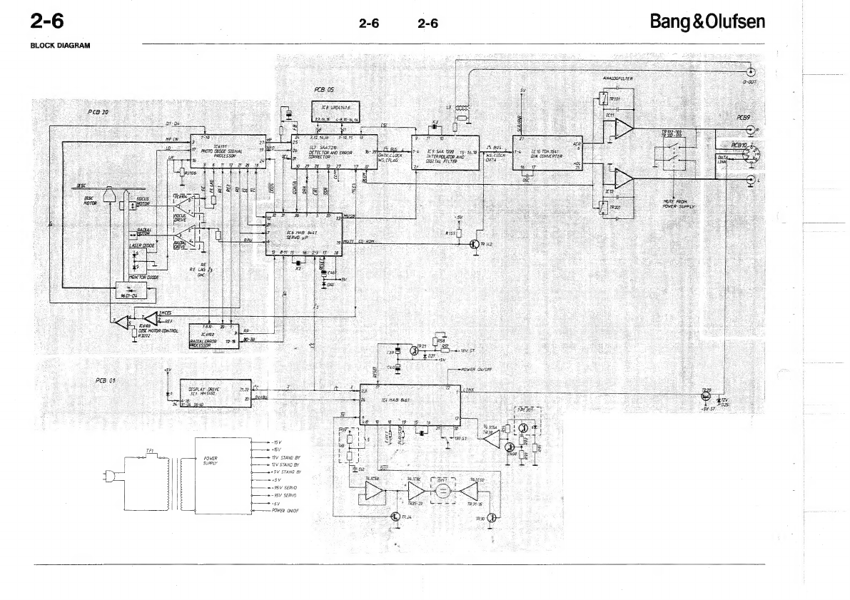
Bang & Olufsen
Bang & Olufsen BeoSound 3000 User manual

Bang & Olufsen
Bang & Olufsen BEOSOUND 9000 Product guide

Bang & Olufsen
Bang & Olufsen BeoSound Century User manual

Bang & Olufsen
Bang & Olufsen BeoSound 3200 User manual

Bang & Olufsen
Bang & Olufsen beogram cd x 5121 User manual

Bang & Olufsen
Bang & Olufsen BeoSound 3000 Product guide

Bang & Olufsen
Bang & Olufsen BEOSOUND 9000 User manual

Bang & Olufsen
Bang & Olufsen BEOSOUND 9000 User manual

Bang & Olufsen
Bang & Olufsen BeoSound 3000 User manual

Bang & Olufsen
Bang & Olufsen BeoSound 9000 MKIII User manual