1.2 How to service, English
How to service, English 1.3
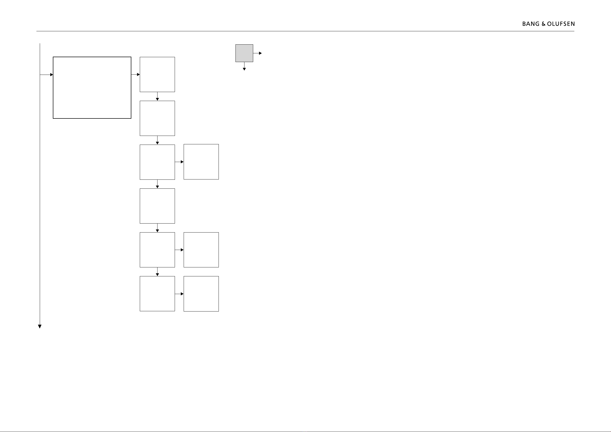
How to service
Strategy
The television is to be serviced in the customer’s home.
The static-protective eld service kit must always be used when the product is
disassembled or modules are being handled.
The repair involves replacement of the chassis, module(s) or Plasma Display Panel,
which are supplied in the back-up suitcase.
The replaced modules must be returned for repair at Bang & Olufsen, Module
Repair Department.
Fault description and error codes must be returned with the replaced parts.
Use the Module Repair form or the form in the Retail Order System, Exchange
Module.
The EEPROM must be transferred to the chassis in the television, hereby
maintaining the customer settings.
Preparations before service
Fault description and error codes must be returned with the replaced parts.
Use the Module Repair form or the form in the Retail Order System, Exchange
Module.
Fault explanation and demonstration
Before troubleshooting is initiated, let the customer demonstrate the fault, if
possible.
Plasma Display Panel pixel test
Check the PDP for burn-in and pixel error! Refer to page 1.19.
The test is used:
- before transporting BeoVision 5 – 42 or the Plasma Display Panel to a workshop.
- before and after service on the Plasma Display Panel.
Error code
The error code contains data that may be used for repairing the module(s) and
must be returned with the module(s).
Handling the error code
1. Take a note of the error code, for example on the Module repair form.
2. Use the error code when trouble shooting.
3. Return the error code, either on the Module Repair form or in the Retail System.
4. Before returning the television to the customer, clear the error code.
Recommended tools for service
Service stand (part no. 3375289).
B&O Test tape, for geometry check (part no. 6780000).
Ruler for geometry check/adjustment.
White gloves.
Micro bre cloth for cleaning (part no. 3375706).
ML-tester (part no. 8053404).
B&O programmer (ML kit must be installed) (part no. 8053368).