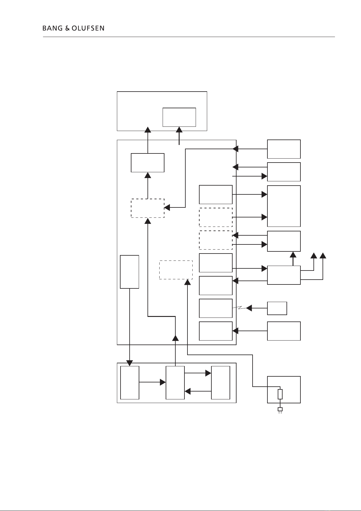
Bang & Olufsen BeoVision 7 MK II User manual

BeoVision 7 – 32 MK III
Type 9331 - 9339
From serial no. 19353358
Service Manual
English
German, French, Italian, Spanish, Danish and Dutch versions
are available in the Retail System
This Service Manual must be returned
with the defective parts/back-up suitcase !

CONTENTS
Survey of modules .................................................................... 1.1
How to service .......................................................................... 1.2
Fault flow chart ......................................................................... 2.1
Adjustments ............................................................................. 3.1
Picture adjustments ................................................................... 3.3
Geometry adjustments .............................................................. 3.6
Final check after repair .............................................................. 3.8
Service mode ............................................................................ 4.1
Replacement of modules ........................................................... 5.1
Specification guidelines for service use ...................................... 6.1
Type survey ............................................................................... 6.5
Wiring diagram ......................................................................... 7.1
Available parts .......................................................................... 8.1

Survey of modules 1.1
Survey of modules
LCD
2
63
6
8
59
4
1
990*
NTC
58
32
77
997
996
73
95 79
76
5
74
72
41
*
990 module*, DVB-S chassis Incl. PCB21, PCB22
996 module, DVD Mechanism Incl. PCB73, PCB76, PCB79, PCB95
997 module, DVD Main chassis Incl. PCB72, PCB77
999 module, Main chassis Incl. PCB1, PCB2, PCB4, PCB5, PCB6,
PCB32, PCB63
PCB41* Home Cinema Control
PCB58 Status Display
PCB59 Camcorder
PCB74 DVD Supply
LCD, PCB8 LCD
*Optional

1.2 How to service
How to service
Strategy
The television is to be serviced in the customer’s home.
The static-protective field service kit must always be used when the product is
disassembled or modules are being handled.
The repair involves replacement of the Main chassis, DVD main chassis, module(s),
fan(s) or LCD panel.
The replaced modules must be returned for repair at Bang & Olufsen, Module
Repair Department.
Fault description and error codes must be returned with the replaced parts.
Use the Module Repair form or the form in the Retail Order System, Exchange
Module.
The EEPROM 6IC6 must be transferred to the chassis in the television, hereby
maintaining the customer settings.
The ServiceTool is required in several service situations, e.g. update of SW or
changing the region setting.
Refer to the ServiceTool for full description of features and operation.
Preparations before service
Always remember to download the latest version of the Service Manual.
Fault description and error codes must be returned with the replaced parts.
Use the Module Repair form or the form in the Retail Order System, Exchange
Module.
Fault explanation and demonstration
Before troubleshooting is initiated, let the customer demonstrate the fault, if
possible.
Error code
The error code contains data that may be used for repairing the module(s) and
must be returned with the module(s).
Handling the error code
1. Take a note of the error code, for example on the Module repair form.
2. Use the error code when trouble shooting.
3. Return the error code, either on the Module Repair form or in the Retail system.
4. Before returning the television to the customer, clear the error code.
Recommended tools for service
B&O ServiceTool.
Service stand.
B&O Test tape, for geometry check. (Part no. 6780000).
Ruler for geometry check/adjustment.
White gloves.
Soft lint-free cloth.
ML-tester.
B&O programmer (ML kit must be installed.
IC-pliers. (Part no. 3629145).

How to service 1.3
Handling and cleaning
Static electricity
Static electricity may damage the television.
Static-protective field service kit.
A static-protective field service kit must always be used when the product is
disassembled or modules are being handled.
Follow the instructions in the guide and use the ESD-mat for both old and new
modules.
Please note:
When mains voltage on the product is required, remove the connection between
the product and the ESD-mat.
The chassis or modules must always be connected to the static-protective field
service kit or placed in an ESD-proof bag.
Symbol of safety components
When replacing components with this symbol, the same type has to be used, also
the same values for ohm and watt.
The new component is to be mounted in the same way as the replaced one.
Lithium battery
WARNING
Short-circuit and overcharging of some types of lithium batteries may result in a
violent explosion.
Transport and handling
It is recommended to:
- place the product in up right position, during service or transport.
- use the product cover when transporting the television.
Mounting or dismounting the service stand
See illustrations page 5.5.
Cleaning
Please refer to the chapter “Final check after repair” or the User’s guides.
STATIC ELECTRICITY
MAY DESTROY THE
PRODUCT
ESD

1.4 How to service
PIN-code
The TV has a 4 digit PIN-code, of the user´s own choice, which must be entered if
the TV has been disconnected from the mains for 15-30 min.
If the PIN-code is activated, and the TV has been without mains for 15-30 min.,
the user will be asked to enter the 4 digit PIN-code when the TV is switched on.
Before the TV is handed in to service it is a good idea to ask the customer to
deactivate the PIN-code.
The PIN-code is activated when the TV is shipped from Bang & Olufsen.
Refer to the user guide for further information
PIN-code active prior to service
If the PIN-code is not deactivated prior to service you must use the Service code to
unlock the product.
Service code
The service code
- unlocks the product, but does not affect the pin-code setting
- gives you 12 hours service time
Entering the Service code
1. When the product asks for PIN-CODE press and hold lfor 3 seconds.
2. The Master code menu appears.
3. Enter the Service code: 1 1 1 1 1.
Important notice concerning Service time
The service time is active as long as the product is connected to the mains, including
Standby.
To obtain maximum service time:
Only connect the product to the mains while you are performing actual service on
the product.
When the service time is expired, the product can only be unlocked by entering
the PIN-code or the Master code.
Registration of the modules
The modules will be registered to the product in the following situations:
- the product has been connected to the mains for more than 12 hours, including
Standby time.
- the PIN-code is activated or deactivated.
PIN-code deactivated by customer prior to service
With the PIN-code deactivated prior to service you must be aware of the modules
will be registered to the product in the following situations :
- the product has been connected to the mains for more than 12 hours, including
Standby time.
- the PIN-code is activated or deactivated.
The registration of modules in the product can only be changed at Bang & Olufsen.

How to service 1.5
Activate the PIN-code
Select the TV SETUP menu.
Press ltwice and then STOP to bring up the PINCODE SETUP menu.
Enter the 4 digit Pin-code. Re-enter the code to confirm it and press GO.
If you want to change or delete the PIN-code, enter the correct PIN-code and press GO.
It is now possible to change the PIN-code or delete the PIN-code.
Enter the PIN-code
If the PIN-code is activated and the TV is disconnected from the mains for more
than15-30 minutes, a PINCODE menu appears as soon as the TV is switched on.
Enter the PIN-code, and the TV starts again.
If the PIN-code has been forgotten
If the PIN-code has been forgotten the only way to unlock the TV again is by
entering a 5 digit Master-code.
The Master-code is ordered by sending a request via the Retail System.
When the TV prompts for a PIN-code, press and hold ldown to bring up the
MASTERCODE menu.
Enter the Master-code and press GO. This will deactivate the PIN-code and
reactivate the TV.
TV locked by PIN-code
The TV is locked by PIN-code when:
- The PIN-code is activated and the mains is disconnected for more than 15- 30
minutes.
The TV is unlocked when the PIN-code is entered.
The PIN-code counter is set to 5 attempts within 3 hours.
When a wrong PIN-code has been entered 5 times within 3 hours, the television
cannot receive any commands for a period of 3 hours.
After this period the PIN-code counter is reset.
The TV must be in standby mode to activate the timer.

1.6

Fault flow chart 2.1
Fault flow chart
Overall block survey
DVB-S
PCB990
STAND
Motorized
SPEAKER
External
Link room
product
External
Camcorder
RF Link
Amplifier
BeoLab 7
Beo4
DSM
PCB32
Power Link
Master Link
TV/
Modulator
PCB63
TV Tuner
IR &
Autocontrast
PCB58
Camcorder
PCB 59
SCALER
LCD driver
Video
processor
SCART
input
PCB2
DVD
power
supply
PCB74
DVD
Main
chassis
PCB997
DVD
Main
mech.
PCB996
DVD
Main chassis
LCD display
BL power
Power
supply

2.2 Fault flow chart
Placement of measuringpoints
A. F220, PCB4
B. W20 (1P7 - 5P119)
C. FP41, 42, 43, 44, PCB4
D. 4P116, PCB4
E. 8P1, PCB8
F. W7 (8P1 - LCD)
G. W5 (5P140 - LCD)
H. 8P2, PCB8
I. W6 (8P2 - 4P116)
J. P167, PCB4
K. Label with Adjustment values
L. P9, PCB1
M. W15 (1P9 - 58P141)
N. 74P103, PCB74
O. 74P114, PCB74
LCD
2
63
6
8
59
4
1
990*
NTC
58
32
77
997
996
73
95 79
76
5
74
72
41
*
B
C
O
N
F
E
H
D
J
A
M
G
I+
G
I
M
D
J
A
L
+
+
+
BK
1
10
24
1
1
14
1
24

Fault flow chart 2.3
System
Fault symptom:
- No start up
- Standby light = No light
Possible causes:
- Missing Mains supply
- Blown mains fuse in BeoLab 7
- Blown mains fuse on Main power supply, PCB4
- Main power supply defect, PCB4
- Status display defect, PCB58
- Other faults in Main Chassis, Module 999
Confirm the Mains
supply is connected
and applied
- - - - - - - -
Mains is applied
- - - - - - - -
Mains supply applied
Connect Mains
supply
Connect Mains supply
directly to BeoVision 7
- - - - - - - -
TV OK?
- - - - - - - -
Blown fuse in BeoLab 7
Fuse F220 on PCB4
OK?
- - - - - - - -
Fuse on PCB4
Replace fuse F220 on
PCB4
- - - - - - - -
TV OK?
- - - - - - - -
Fuse on PCB4
Replace Main chassis
(module 999)
- - - - - - - -
Fault in the television
Check fuse in BeoLab 7
- - - - - - - -
Mains is applied
- - - - - - - -
Fuse in BeoLab 7
Fault may be located
in any of the PCBs
Replace Main Chassis
(module 999)
Replace
Status display
PCB58
BeoLab 7
F220
PCB4
Action
- - - - - - - -
Confirm
- - - - - - - -
Checked
No
Yes

2.4 Fault flow chart
Fault symptom:
- No start up
- Standby light = red
Possible cause:
- PIN-code locked
- Option 0
- Status display defect
- Mains chassis defect
- Beo4 / Remote control defect
Press TV on the Beo4
- - - - - - - -
OSD displays “WAIT”
- - - - - - - -
PIN-code locked
Set the television in
OPTION 1
- - - - - - - -
Does St-by. led blink
one time?
- - - - - - - -
Option 0 = Status
display is disabled
Ensure that the
television is in
Standby mode
- - - - - - - -
The television has
been locked for 3
hours since last PIN-
code was entered
Press TV on the Beo4
- - - - - - - -
TV OK?
- - - - - - - -
Status display is
enabled
Replace Main chassis
(Module 999)
- - - - - - - -
Main chassis defect
Check the Beo4 on
another product
- - - - - - - -
Other product
responds correctly
- - - - - - - -
Beo4
Replace the batteries
in the Beo4
- - - - - - - -
TV OK?
- - - - - - - -
Beo4
Beo4 defect
Try a new Beo4
- - - - - - - -
TV OK?
- - - - - - - -
Beo4
Fault may be located
in any of the PCBs
The old Beo4 is defect Replace Main chassis
(module 999)
Replace
Status display
(PCB58)
Action
- - - - - - - -
Confirm
- - - - - - - -
Checked
No
Yes

Fault flow chart 2.5
Fault symptom:
- ML error
Possible causes:
- Main Chassis defect
- ML connection defect
- ML cable defect
- Incorrect option setup
Make a record of the
last ML error
Clear the error codes
- - - - - - - -
Television self
diagnosis
Turn OFF the
BeoVision 7
Disconnect the ML cable
- - - - - - - -
Prepare to test the
BeoVision 7 as stand-
alone
Turn ON the BeoVision 7
Make a record of the last ML error
- - - - - - - -
ML = ...
- - - - - - - -
Determine if the fault is located in the ML
installation
Replace Main chassis
(Module 999)
- - - - - - - -
ML error in main
chassis
Turn OFF the
BeoVision 7
Disconnect all ML
cables in the ML
setup
Check ML
connections
Use the ML-tester or
a new cable
Connections OK?
- - - - - - - -
ML cables and
installation
Reestablish the ML
connection
Reestablish and
configure the ML
setup one product at
a time.
(repeat until ML setup
is complete)
MasterLink OK?
Fail may be located in
the Link product
3
2
1
-,
CIRCUIT ,INKPRODUCT
,INKPRODUCT
"EO6ISION
ML error survey:
Error code Error
... No error
TU ML pulled up
TD ML pulled down
CI Configuration impossible
?? Other error
Action
- - - - - - - -
Confirm
- - - - - - - -
Checked
1
2
3
No
Yes

2.6 Fault flow chart
Fault symptom:
- No picture
- Status display OK (source)
Possible causes:
- No backlight
- Fault in video path
- LCD defect
- Defect connection
- Defect RF link amplifier
Picture
Press MENU on Beo4
- - - - - - - -
OSD on display?
- - - - - - - -
Video path to LCD
SCALER & LCD
Action
- - - - - - - -
Confirm
- - - - - - - -
Checked
Visual inspection of
backlight, through
ribbons in backcover
- - - - - - - -
Backlight lit?
- - - - - - - -
LCD active
No backlight
See next page
Press TV on Beo4
- - - - - - - -
Snow or poor picture?
- - - - - - - -
TV tuner and video
path
Check if “DECODER
ON” in TV MANUAL
TUNING
- - - - - - - -
Decoder ON
- - - - - - - -
User setting
Connect ServiceTool
to BeoVision 7
- - - - - - - -
Prepare for Scaler Test
Pattern
Set “DECODER ON”
in TV MANUAL
TUNING
- - - - - - - -
Picture OK?
- - - - - - - -
User setting
Communication
between ServiceTool
and BeoVision 7 OK?
- - - - - - - -
Scaler PCB + ML
connection
Check antenna
connection
- - - - - - - -
Connection between
antenna output and
BeoVision 7
- - - - - - - -
Antenna connection
Reestablish the
connection
- - - - - - - -
Picture OK?
Activate a test picture
in the Scaler Test
Picture Menu
- - - - - - - -
Picture OK?
- - - - - - - -
Video path Scaler to
LCD
Connect antenna
directly to tuner
- - - - - - - -
Picture OK?
- - - - - - - -
RF Link amplifier
Perform a manual TV
tuning
- - - - - - - -
Picture OK?
Replace Main chassis
(Module 999)
Check W20 RGB
connection
- - - - - - - -
Connection OK?
- - - - - - - -
Cable connection
Reestablish
connection
- - - - - - - -
Picture OK?
Replace Main chassis
(Module 999)
1
2
3
4
5
6
Replace
RF Link amplifier
No
Yes

Fault flow chart 2.7
2
8
H
Pu
]
b
P
[
D
N
G
V
42
+
FF
O/N
O
N
I_
M
ID
A
M
W
P
]
2
P
[
Y
L
PPU
S
_LB
D
N
G
M
WP
N
I_
M
ID
A
F
FO
/NO
]
1P[
DNG
V
4
2+
FF
O
/
N
O
N
I_M
ID
A
M
WP
]611
P
[
]391
P
[
Y
L
P
P
US_L
B
D
N
G
]
61P[
subCI
I
cn
y
S
-H
LR
T
CRELA
C
S
1
2W
k
n
iLretsaM
noit
c
enno
c
looT
e
civreS
7
W
l
ang
iS
1bcp y
l
ppus
r
e
w
oP
4bcp
gn
ilpuo
c
eD
8bcp
DC
L
]
a
P[
__
__
X
R
-
-----
V
5+
-
--
---
L
TR
C
RELA
C
S
5
b
c
P
]04
1P[
XT
]
7
4
1
P[
V5
+
5W
]321P[
LRTC
]
4
21P
[
subCII
cn
y
S-H
LRTCRELAC
S
]911P
[
L_CP
R_
C
P
R
G
B
RE
LAC
S
nrettaPtse
T
ro
tareneg
]
0
6
1P
[
T
X
E
_
N
O_THGI
L
B
TX
E_1
A
_T
HGI
L
B
TXE
_M
WP_TH
G
I
LB
]7P[
L
_C
P
R
_
C
P
R
G
B
ecruoSo
e
diV
&
D
S
O
]
871P[
SBVC_
C
P
F
F
O
/
N
O
_P
PU
S
_
LB
_PEF
NO_REL
A
CS
]51
P
[
V41+
L
B_ET
U
M_
SN
IAM
]811P[
V41+
LB_E
T
UM_
S
N
IAM
3
2W
22
W
02
W
]
9
71P[
SBVC_CP
FFO
/
NO_
Y
LP
PU
S_LB
NO
_
REL
AC
S
h
c
tiws
]6
P
[
NO_
YLP
PUS
_
L
B
DNG
]
7
6
1
P
[
NO_YL
P
P
US_
LB
D
N
G
r
e
wo
p
LB
y
lp
pus
01
W
6
W
3
1
4
Tuner/IF
RF Link amplifier
(external box)
6
7
antenna
]831
P
[]631
P
[

2.8 Fault flow chart
No backlight
Measure Power supply to
backlight LCD from PCB4
- - - - - - - -
+24V at 4FP 42, 43 or 44
or
4P116 pin1-5
- - - - - - - -
Output from PCB4
Measure CTRL signal
BL_SUPPLY to PCB4
- - - - - - - -
>+4V at 4FB 41 or
4P167 pin 5
- - - - - - - -
CTRL signal from PCB1 = ON,
Cable: W10, BL power supply
Measure power supply
to backlight LCD
- - - - - - - -
+24V at 8P1 pin 10-14,
pin 5-9; GND
- - - - - - - -
Output from PCB4,
Cable: W6
Measure power supply
to backlight LCD
- - - - - - - -
+24V at 8P2 pin 1-5,
pin 6-11; GND
- - - - - - - -
Output from PCB4,
Cable: W6
Check cable W6
- - - - - - - -
Connection OK?
- - - - - - - -
Connection W6
PCB4 to PCB8
Replace Main chassis
(Module 999)
- - - - - - - -
Fault may be located
in either PCB4 or PCB1
Replace PCB8
- - - - - - - -
PCB8 is defect
Reestablish or replace
the connection
- - - - - - - -
Fault may be in the
connection
Measure CTRL signal
LCD ON
- - - - - - - -
>+4V at 8P1 pin3
- - - - - - - -
CTRL signal from PCB5
= ON, circuit on PCB8
and cable W6
Measure CTRL signal
LCD ON
- - - - - - - -
>+4V at 8P2 pin12
- - - - - - - -
CTRL signal from PCB5
= ON, circuit on PCB8
and cable W6
Measure CTRL signal
LCD ON
- - - - - - - -
>+4V at 5FP2
pin12
- - - - - - - -
CTRL signal from
PCB5 = ON
Replace Main chassis
(Module 999)
- - - - - - - -
Fault is located in the
Main chassis
Check cable W7
- - - - - - - -
Conection OK?
- - - - - - - -
Connection W7 LCD
to PCB5
Replace PCB8
- - - - - - - -
PCB8 is defect
Action
- - - - - - - -
Confirm
- - - - - - - -
Checked
Check cable W6
- - - - - - - -
Connection OK?
- - - - - - - -
Connection W6, PCB5
to PCB8
Check cable W5
connected ad LCD
- - - - - - - -
Connection OK?
- - - - - - - -
Connection W5 LCD
to PCB5
Reestablish or replace
the connection
- - - - - - - -
Fault may be in the
connection
Fault may be located in
either Main chassis or
LCD panel
Replace Main chassis
(Module 999) LCD defect
1
2
3
4
10
20 21
30 31
5
Reestablish
connection
No
Yes

Fault flow chart 2.9
FP41
FP43
FP42
FP44
PCB4
PCB1 PCB8
PCB5

2.10 Fault flow chart
Fault symtom
- No colour(s)
Possible cause
- Video path
- Scaler
- LCD
Check/adjust colour
settings in
OPTIONS - PICTURE
- - - - - - - -
Colours OK?
- - - - - - - -
Settings OK
Restore correct colour
setting
Activate a test picture
in the Scaler
Test picture menu
Red, Blue, Green
- - - - - - - -
Colours OK?
- - - - - - - -
LCD tested
Fault may be located
in either Scaler or LCD
Replace Main chassis
(Module 999)
- - - - - - - -
Scaler fault
- - - - - - - -
Fault in Scaler output?
Replace LCD
- - - - - - - -
LCD fault
- - - - - - - -
Fault in Scaler output
Check W20
- - - - - - - -
Connection OK?
- - - - - - - -
RGB connection from
Main chassis
Reestablish
connection
Picture OK?
Replace Main chassis
(Module 999)
1
2
Action
- - - - - - - -
Confirm
- - - - - - - -
Checked
No
Yes
PCB1
PCB5

Fault flow chart 2.11
Fault symptom
- TV channels only
- Noise in picture
- Noise in sound
Possible causes
- Poor channel tuning
- Defect RF Link Amplifier
- Poor connection from antenna
- Main Chassis defect
- Incorrect Tuner/If adjustment
Noise on single TV
channel
Check and adjust
channel tuning
- - - - - - - -
Pictures without noise
- - - - - - - -
Channel tuning
Replace Main chassis
(Module 999)
Noise on all TV
channels
Connect antenna cable
directly to the tuner
input
- - - - - - - -
Picture without noise
- - - - - - - -
RF Link amplifier
Replace RF Link
amplifier
- - - - - - - -
Defect RF Link amplifier
Check antenna
connection
- - - - - - - -
Cable and connector
OK
- - - - - - - -
Cable & connector
Check adjustment
Tuner Takeover, IF adjust
& FM sound adjust
- - - - - - - -
Values set to values on
label
- - - - - - - -
Tuner & IF adjustment
Reestablish antenna
connection &
reestablish RF Link
amplifier - tuner
connection
Adjust Tuner Takeover,
IF adjust & FM sound
adjust
- - - - - - - -
Picture without noise
Replace Main Chassis
(Module 999)
32
1
4
)&
4UNER
2&,INK
AMPLIFIER
!DJUSTMENT
4UNING
Action
- - - - - - - -
Confirm
- - - - - - - -
Checked
1
2 3
4
No
Yes

2.12 Fault flow chart
Fault symptom
- No autocontrast
Possible cause
- Defect autocontrast
- Defect Main Chassis
- Poor connection, W15
Check voltage on
PCB1 P9 pin 10
- - - - - - - -
Covered sensor app.
7.4V
Full light app 6.8V
- - - - - - - -
Sensor circuit on
PCB58
Replace Main chassis
(Module 999)
Check W15
- - - - - - - -
Connection between
Main chassis and
Status display
Replace Status display
(PCB58)
Action
- - - - - - - -
Confirm
- - - - - - - -
Checked
2
1
0PIN
3TATUS
$ISPLAY
-AIN#HASSIS
1
2
No
Yes
This manual suits for next models
4
Table of contents
Other Bang & Olufsen Monitor manuals