Bang & Olufsen BeoVision 4-85 User manual

BeoVision 4-85
Installation Guide for BeoVision 4-85, Wall Bracket
Version 1.1

Introduction 2
Introduction
The aim for this Guide is to assist the installer to attain a smooth and correct installation. The Guide is intended as a Guideline and may in certain
cases not be 100% relevant. However, the Guide could be useful as a reference book to nd information about the product as well as dimentions.
Content
This Installation Guide describes the following:
- Precautions
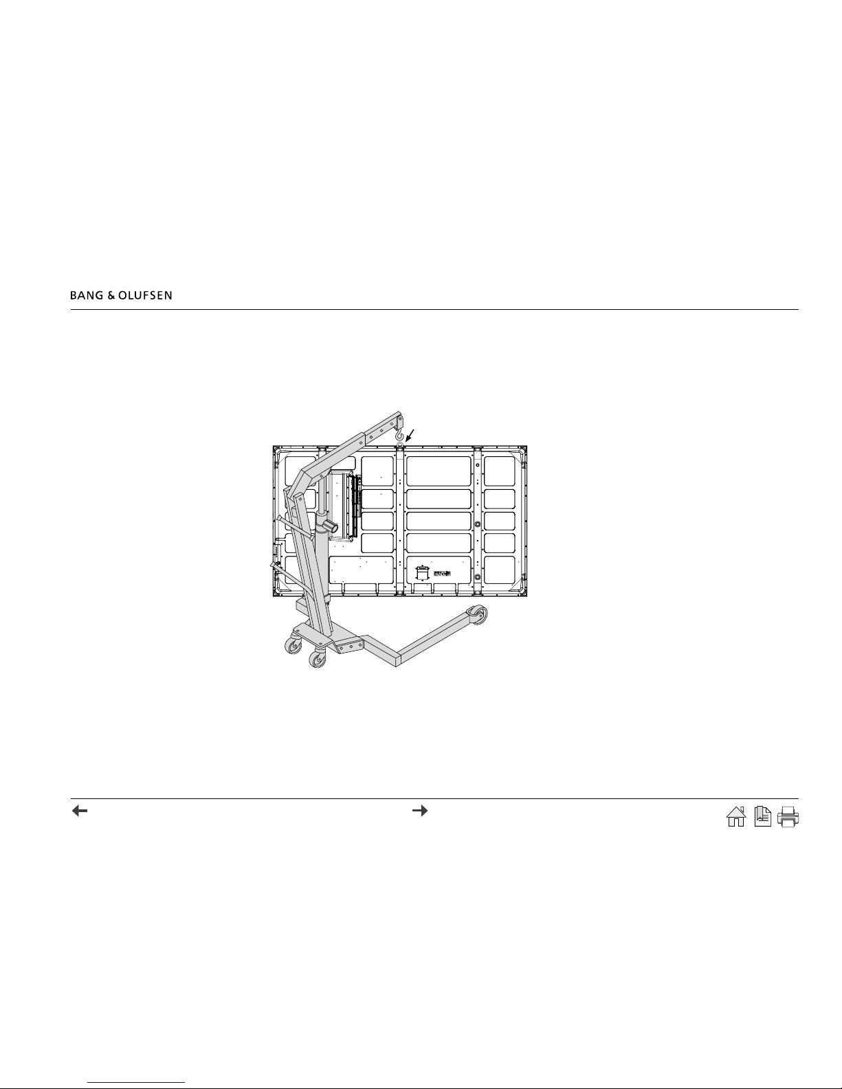
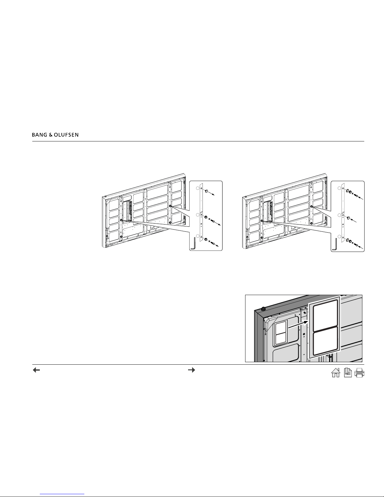
- Assembly and installation of Wall Bracket
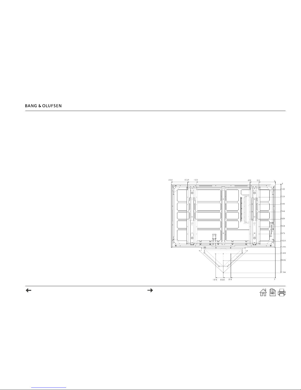
- Mechanical specications for BeoVision 4-85, Wall Bracket.
Important
! Since both the plasma panel and the stand are sizeable products, it is strongly recommended to read the warning and precautions section carefully.
Otherwise there is major risk of damaging personnel or furniture.
How to navigate this Guide
When the Guide is opened, it automatically opens in Full Screen Mode (can be left as desired - see below). This is primarily done to optimize the
usability of screen reading. There are several ways to navigate when using the Guide, see the survey of keys, shortcuts and hotkeys below:
/ (arrow keys on the keyboard) navigates to the next page
/ (arrow keys on the keyboard) navigates to the previous page
Esc (Esc button ) exits Full Screen Mode (press CTRL + L to return to Full Screen Mode).
Another feature to optimize the navigation is the navigation icons in the bottom of the screen (see explanation below).
Navigates directly to the start page
Navigates directly to the table of contents (these are active links - click the link to be directed directly to the chapter)
Prints the document - the print dialog box opens (Ctrl + P also brings up this feature)
Furthermore to ease the navigation, this Guide contains links. The links are mouse-over active and marked with blue text. Just click on a page
reference to be transferred to that page.

Introduction 3
Warning
Before the installation is started it is strongly recommended to ensure the following:
! Ensure that the wall construction is strong enough to support long-term use. If its strenght becomes insufcient over the course of long-
term use, the product may fall down, and possibly cause injury.
! Installation and removal should be carried out by qualied installers only. If the Wall Bracket is installed incorrectly, the TV may fall down,
and possibly cause injury.
! Do not install in places which are subject to high humidity, dust, oil fumes, water vapour or excessive heat. These can have adverse
effects on the plasma display operation, and re or electric shocks may occur.
! Exercise caution when selecting the location for the TV. It may discolor or deform due to light or heat if it is placed where it is exposed
to direct sunlight, or near a heater.
!Only moving companies are allowed to lift or move the TV.
Not technicians or installers.
Precautions
Before the installation is started it is strongly recommended to read this Guide carefully. The description is only intended as a guiding
instruction which may vary compared to the actual situation.
Edges of the items
The shape of BeoVision 4-85 and the Wall Bracket may be considered potential risks when they are free-hanging items. To avoid getting
injured, be aware of their positions when they are free-hanging in the active working area during the installation.

Installation overview 4
Installation overview
Apart from the Wall Bracket, the basic set-up of BeoVision 4-85 includes the following items:
- BeoVision 4-85 PDP (Plasma Display Panel) incl. IR, ACM and shielding frames
- BeoSystem 3
- BeoLab 10
The Wall Bracket installation includes:
- Two Wall Brackets
- A special mounting bracket for BeoLab 10
- EMC gaskets
- Decorative plates
- Side panels for covering the Wall Bracket
Introduction
Warning/Precautions
Installation overview
Installation, Wall Bracket
Installation, TV
Installing the TV on the
Wall Bracket
Installing shielding
frames
Connecting cables to TV
Installing BeoLab 10
Connecting products
Setting-up PDP settings
Placing decorative plates
Technical specications

Installation overview 5
Weight
When the TV is moved, a crane can be used (recommended). The items are too heavy to move and it is strongly recommended to not attempt lifting
them manually.
! Only moving companies are allowed to lift or move the TV. Not technicians or installers.
There is no requirements to which type of crane to use, but in order to attain a smooth
and safe operation, it is recommended to use a crane like this:
L = 105-155cm, length of reach
(for Wall Bracket installation)
95-135cm, length of reach
(for Floor Stand installation)
H = ≥ 235cm (height)
W = ≥ 98cm (width)
The weight of BeoVision 4-85 is approx. 150 kg.
It is recommended to use a crane which is approved to handle loads up to 350 kg.
The reason is to ensure a safe and steady installation.
Environment
It is strongly recommended to pay attention to the environment where the installation is going to take place. It is very important that all kinds of
precautions are made to prevent damages to the environment (oors, walls, furnitures etc.).
Placement
Be sure that the surface where the product is going to be placed, is plane and the building design meets the required loads.
L
H
W

Installation, Wall Bracket
The elements in the Wall Bracket installation consists of mounting the Wall Bracket and TV installation.
To ensure a smooth installation it is recommended to follow a structured procedure. Please follow the suggested procedure below:
- Mounting the Wall Bracket.
- Unpacking and removing the TV from the packaging, replacing eyebolts on TV/mounting EMC caps.
- Installing the TV on the Wall Bracket, installing shielding frames, installing BeoLab 10.
- Connecting products.
- Installing decorative plates.
Mounting the Wall Bracket
There are no rules for the mounting procedure, but it is recommended to perform the measurement of the drilling holes in a coordinate system.
- Drill the necessary holes for the Wall Brackets.
Check twice - drill once!
- Mount the two Wall Brackets with the necessary bolts.
! Be sure that the surface where the TV is going to be placed,
is plane and the building design meets the required loads.
- Drill the holes for the mounting bracket, BeoLab 10.
- Mount the mounting bracket, BeoLab 10 with the necessary bolts.
! The mounting bracket is the distance piece for the Wall Bracket, BeoLab 10.
Installation, Wall Bracket 6

Installation, TV 7
Installation, TV
Placement of TV in packaging
The purpose of this step is to place the BeoVision 4-85 in its packaging in an appropriate place. The aim is to obtain as little moving of the TV as
possible, which is a great advantage when moving large objects. It is prudent to conduct a test run of the transport without the TV mounted on
the crane. See the example below.
! Becarefultocovertheoorwithprotectionmaterials
topreventdamagingthesurface.Althoughthepackageis
sound,therecanbedamagetotheoorifgreatcautionis
notexercised.
When the test run seems to proceed smooth, place the TV
in its packaging where planned.
A
D
B
CA =
D =
C =
B =
=
Wall
BV4 – 85 in packaging
Crane
BV4 – 85 on Wall Bracket
Necessary workspace
TV front side
When the Wall Bracket and the mounting bracket, BeoLab 10
are correctly mounted the placement looks like this:
> Mount the top/bottom bars for the Wall Bracket
Floor
Top bar
Bottom bar
5mm (x4)

Removal of TV packaging 8
Removal of TV packaging
When the product is placed in its packaging the next step is to remove the packaging parts. Follow the procedure below:
> Remove the securing belts > Remove the top packaging > Remove the front packaging
> Remove the four frame parts
> Remove the three foam parts > Remove sides and back part

Removal of TV from packaging 9
Removal of TV from packaging
The TV is now free-standing and ready for transport. When the TV is removed and free from the packaging, the plates and the EMC gaskets must
be installed. Follow the procedure below (depending of the crane type the procedure may vary):
> Mount the eyebolt in the centered thread hole as shown below:
> Place the crane in front of the TV and secure the crane claw to the eyebolt on the TV.
> Lift off the TV from the packaging
(it is recommended to have at least one person steering the crane and two persons steering the TV to prevent damaging the product).
> Pull the crane with the TV away from the packaging.

Replacing stand hooks on TV / mounting EMC caps
The next step is to replace the stand hooks (as delivered from factory) and mount the EMC caps. This is necessary to be able to attach
the TV to the Wall Bracket and to ensure elimination of EMC (ElectroMagnetic Compatibility). Follow the procedure below:
Replacing stand hooks on TV / Notice PDP values 10
> Mount the two stand hook caps (L/R) from position A in position B
as shown.
> Mount the four stand hooks (L/R) from position B/C and the four
EMC caps in position A/C as shown.
> Remove the two stand hook caps (position A).
> Remove the four stand hooks (position B/C ). >>>
A
A
B
(x2)
C
(x2)
A
A
B
C
10 mm 10 mm
WPR=
WPG=
WPB=
RCT=
GCT=
BCT=
CONOF=
182
240
154
125
113
120
48
Bsys3
Entervalues in to
Panel/PWadjust menu
WPR=
WPG=
WPB=
RCT=
GCT=
BCT=
238
240
230
125
113
120
Bsys3
Entervalues in to
Panel/PW3D adjust
menu
WPR=
WPG=
WPB=
RCT=
GCT=
BCT=
CONOF=
182
240
154
125
113
120
48
Bsys3
Entervalues in to
Panel/PWadjust menu
WPR=
WPG=
WPB=
RCT=
GCT=
BCT=
238
240
230
125
113
120
Bsys3
Entervalues in to
Panel/PW3D adjust
menu
Locate/Notice PDP values
Before the TV is installed on the Wall Bracket it is wise to write down the
panel values, which are printed on the label located on the back of the TV.
> Locate and write the values from the label.
WPR =
WPG =
WPB =
RCT =
GCT =
BCT =
CONOF=
182
240
154
125
113
120
48
Bsys3
Enter values in to
Panel/PW adjust menu
WPR =
WPG =
WPB =
RCT =
GCT =
BCT =
238
240
230
125
113
120
Bsys3
Enter values in to
Panel/PW 3D adjust
menu
WPR =
WPG =
WPB =
RCT =
GCT =
BCT =
CONOF=
182
240
154
125
113
120
48
Bsys3
Enter values in to
Panel/PW adjust menu
WPR =
WPG =
WPB =
RCT =
GCT =
BCT =
238
240
230
125
113
120
Bsys3
Enter values in to
Panel/PW 3D adjust
menu

Installing the TV on the Wall Bracket 11
Installing the TV on the Wall Bracket
Now the TV is ready to be installed on the Wall Bracket.
> Move the TV with the crane to the Wall Bracket
> and attach the four stand hooks to the four notches.
! It is recommended to have at least one person steering the crane and two persons steering the TV to prevent damaging the product.
- Lower the crane arm carefully and release the hook from the eyebolt. Remove the crane from the TV and remove the eyebolt.

Installing shielding frames 12
Installing shielding frames
Install the four shielding frames (MDF supplied with the TV) in the following order:
Shielding frame
WPR=
WPG=
WPB=
RCT=
GCT=
BCT=
CONOF=
182
240
154
125
113
120
48
Bsys3
Entervalues in to
Panel/PWadjust menu
WPR=
WPG=
WPB=
RCT=
GCT=
BCT=
238
240
230
125
113
120
Bsys3
Entervalues in to
Panel/PW3D adjust
menu
WPR=
WPG=
WPB=
RCT=
GCT=
BCT=
CONOF=
182
240
154
125
113
120
48
Bsys3
Entervalues in to
Panel/PWadjust menu
WPR=
WPG=
WPB=
RCT=
GCT=
BCT=
238
240
230
125
113
120
Bsys3
Entervalues in to
Panel/PW3D adjust
menu
Screws
> Shielding frame top > Shielding frame bottom
>>> ! Itisimportantthattonguedandgroovedtsperfectly.
> Shielding frame left/right > Tighten the 20 screws to lock the shielding frames
>>>
Shielding frame

Connecting cables to TV 13
WPR=
WPG=
WPB=
RCT=
GCT=
BCT=
CONOF=
182
240
154
125
113
120
48
Bsys3
Entervaluesin to
Panel/PWadjustmenu
WPR=
WPG=
WPB=
RCT=
GCT=
BCT=
238
240
230
125
113
120
Bsys3
Entervaluesin to
Panel/PW3Dadjust
menu
WPR=
WPG=
WPB=
RCT=
GCT=
BCT=
CONOF=
182
240
154
125
113
120
48
Bsys3
Entervaluesin to
Panel/PWadjustmenu
WPR=
WPG=
WPB=
RCT=
GCT=
BCT=
238
240
230
125
113
120
Bsys3
Entervaluesin to
Panel/PW3Dadjust
menu
Connecting cables to TV
- Connect the cables to the connectors on the TV as shown:
AV module:
- HDMI cable -> to BS3
- RS232 cable -> to BS3
- 3D shutter out -> to 3D socket
IR/Camera module:
- Camera cable -> from camera module
- IR-out cable -> to BS3
- IR-in cable -> from auto contrast
- IR/blast cable -> from IR-bar
IR/blast cable:
Secure the cable with cable ties as shown.
TV mains socket:
- Connect the mains cable to the TV.
Secure the cable with the clips as shown.

Installing BeoLab 10 14
Installing BeoLab 10
The next step is to install BeoLab 10. Please follow the procedure below:
> Install the BeoLab 10 Wall Bracket on the mounting bracket for BeoLab 10. Adjust
the position of the Wall Bracket, BeoLab 10 (shown below):
! Tip: Do not tighten the screws more than it is still possible to gently move the
position of the bracket (it must be exactly strong enough to hold its position).
> Install the mains cable and the Power Link cable for BeoLab 10.
> Mount BeoLab 10 on the Wall Bracket for BeoLab 10. Adjust the position of
BeoLab 10 as shown below:
> Remove BeoLab 10 and tighten the screws holding the Wall Bracket completely.
> Connect the mains cable and Power Link cable to BeoLab 10 and install the
speaker on the Wall Bracket.
> Remove the front cloth for BeoLab 10 and tighten the three screws at the front of
the speaker to lock the speaker position.
> Mount the front cloth on BeoLab 10.
Wall Bracket
Mounting bracket
Screws =

Connecting products / Setting-up PDP settings / Placing decorative plates 15
Connecting products
The last step is to connect the necessary cables to the TV and BeoSystem3, set-top boxes, to mains, etc. Follow the procedure below:
> Connect HDMI, IR and RS232 cable from BeoVision 4 to BeoSystem3.
> Connect the desired number of set-top boxes to the respective connections on BeoSystem3.
For further information please refer to BeoSystem 3 Installation Guide (can be downloaded from Bang & Olufsen Retail System/BeoWise).
> Place BeoSystem3 on the mounting bracket, BeoLab 10.
> Connect BeoVision 4 and BeoSystem3 to the mains.
Setting-up PDP settings
Enter the panel display data in the Service Menu by the following procedure:
> Switch on BeoVision 4 by pressing TV.
> Enter Service Menu by pressing: MENU 00 GO/OK.
Choose: MONITOR - PICTURE ADJUSTMENTS - PANEL/PW ADJUST
and enter the values from the upper label.
Choose: MONITOR - PICTURE ADJUSTMENTS - MONITOR SETTINGS -
PANEL/PW 3D ADJUST and enter the values from the lower label.
> Exit the Service Menu.
Placing decorative plates
- Finish the installation by mounting the two panel covers as shown here:
The installation is now completed and the area is ready for a clean-up
(packaging, tools, etc.).
WPR=
WPG=
WPB=
RCT=
GCT=
BCT=
CONOF=
182
240
154
125
113
120
48
Bsys3
Entervalues in to
Panel/PWadjust menu
WPR=
WPG=
WPB=
RCT=
GCT=
BCT=
238
240
230
125
113
120
Bsys3
Entervalues in to
Panel/PW3D adjust
menu
WPR=
WPG=
WPB=
RCT=
GCT=
BCT=
CONOF=
182
240
154
125
113
120
48
Bsys3
Entervalues in to
Panel/PWadjust menu
WPR=
WPG=
WPB=
RCT=
GCT=
BCT=
238
240
230
125
113
120
Bsys3
Entervalues in to
Panel/PW3D adjust
menu
WPR =
WPG =
WPB =
RCT =
GCT =
BCT =
CONOF=
182
240
154
125
113
120
48
Bsys3
Enter values in to
Panel/PW adjust menu
WPR =
WPG =
WPB =
RCT =
GCT =
BCT =
238
240
230
125
113
120
Bsys3
Enter values in to
Panel/PW 3D adjust
menu
WPR =
WPG =
WPB =
RCT =
GCT =
BCT =
CONOF=
182
240
154
125
113
120
48
Bsys3
Enter values in to
Panel/PW adjust menu
WPR =
WPG =
WPB =
RCT =
GCT =
BCT =
238
240
230
125
113
120
Bsys3
Enter values in to
Panel/PW 3D adjust
menu

Technical specications 16
Technical specications
Weight
Item Item weight Packing Total
Monitor 144 kg 89 kg 233 kg
Wall Bracket 19 kg 3 kg 22 kg
Speaker box 2.35 kg 1.9 kg 4.25 kg
BeoLab 10 13 kg - -
Size (W x H x D)
Item Item size Packing size
Monitor (without Wall Bracket) 205.2 x 125.9 (+ IR
eye 2.5) x 14.4 cm
223.5 x 153.5 x 80 cm
Monitor (with Wall Bracket) 205.2 x 125.9 (+ IR
eye 2.5) x 22.1 cm
-
Wall Bracket 144.8 x 113 x 10.7cm 155 x 26 x 26 cm
Speaker box (type 4498) 67.6 x 31 x 8.1 cm 75.5 x 36 x 25.6 cm
BeoLab 10 95 x 48 x 13 cm 111 x 65 x 33 cm
Illustration of TV transport box

Technical specications 17
Outer dimensions
Front view

Technical specications 18
Top view
Right side view

Technical specications 19
Drilling measurements

Contents / Installation overview 20
Contents Introduction ...................................................................................... 2
How to navigate this Guide ........................................................... 2
Warning / Precautions ................................................................... 3
Installation overview ........................................................................ 4
Installation, Wall Bracket ................................................................. 6
Mounting the Wall Bracket ........................................................... 6
Installation, TV .................................................................................. 7
Placement of TV in packaging ....................................................... 7
Removal of TV packaging .............................................................. 8
Removal of TV from packaging ..................................................... 9
Replacing stand hooks on TV ...................................................... 10
Locate/notice PDP values ............................................................. 10
Installing the TV on the Wall Bracket ........................................... 11
Installing shielding frames ............................................................. 12
Connecting cables to TV ................................................................ 13
Installing BeoLab 10 ....................................................................... 14
Connecting products ...................................................................... 15
Setting-up PDP settings .................................................................. 15
Placing decorative plates ............................................................... 15
Technical specications .................................................................. 16
Introduction
Warning/Precautions
Installation overview
Installation, Wall Bracket
Installation, TV
Installing the TV on the
Wall Bracket
Installing shielding
frames
Connecting cables to TV
Installing BeoLab 10
Connecting products
Setting-up PDP settings
Placing decorative plates
Technical specications
12-02
Other manuals for BeoVision 4-85
1
Table of contents
Other Bang & Olufsen Plasma TV manuals
Popular Plasma TV manuals by other brands

Panasonic
Panasonic TH-42PD60U, TH-42PD60X Service manual

Panasonic
Panasonic Viera TH-P42ST30Z operating instructions

Fujitsu
Fujitsu AVIAMO P65FT00AUB Specifications

Gateway
Gateway 50-inch Specifications

Panasonic
Panasonic TH-37PG9U Manual de instrucciones

Panasonic
Panasonic VIERA TC-P50GT30 owner's manual