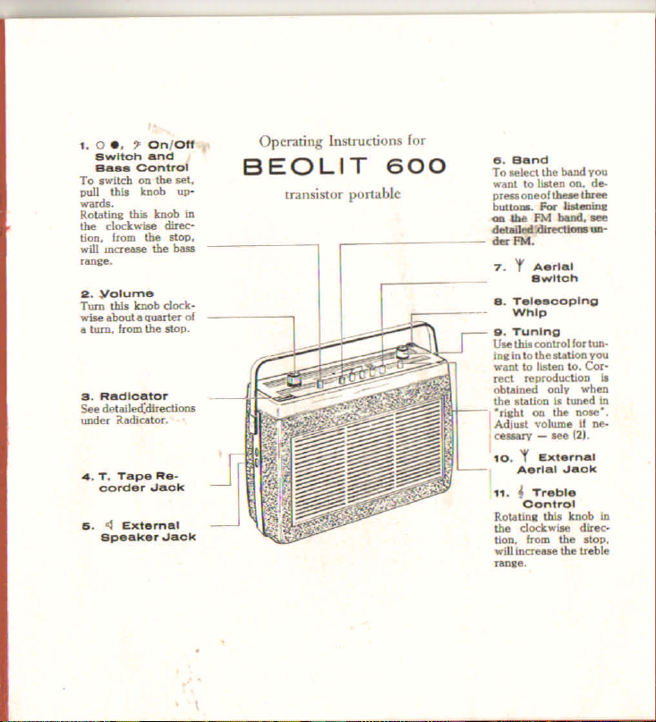
Bang & Olufsen Beolit 600 User manual


~~)lo~urne
~ a~~tknob dock:.
i
turn. frox:.
Q
thuarter of
estop.
53. Radloator
toedetailed:dir
under aadicat ections
0< •
••• T. Tape R
oorder .Ja';;-k
G.
3
External
Speaker .Jack
B
Operating Instructions
fOT
EOLIT 600
transistor portable
. B nd
To
IIelect
the
want to list band you
pressoneol~n. de.
butto. Foe _ three
~ the .FM Usteainc
detai1ed~~
.:fer
Rot. ....-
7.
'f
Aerial
Switch

Radieator
The set Is equipped with a Radicator, which indicates the battery voltage and
facilitates tuning.
To check the battery voltage, switch on the receiver and set its controls so
that no station is received. The easiest way of doing this Is to depress the M
and MA buttons at the same time. The Radicator pointer will go to the green
section of the scale If the battery is O.K. If the pointer goes only to the red
scale section, the battery is spent and should be replaced. The set may still be
able to work but It will not be capapleof full performance, and there Is a dan.
ger that the dry cells may give off liquid, which may damagethe receiver.
To tune in a station. rotate the tuning control until the station you want to
listen to makes the Radlcator pointer go as far to the right on the scale as
possible. When receiving on the built-In aerials of the set it is Important that
you rotate the set and move It about until you find the position of the set that
will bring the Radicatorpointer as far to the right as possible. Rotatingthe set
and moving it about is especially Important when you want to listen to aweak
station indoors as reception may vary considerably between places only a few
yards apart, due to water pipes, concrete reinforcement, etc.
AM Reception on the Long waves, Medium waves and Marine band
The receiver Incorporates a high sensitivity ferrite aerial for best reception on
the LW, MW and Marine band. This aerial is mounted longitudinally in the set.
and because it is somewhat directive. rotation of the receiver may improve
reception of weak signals. If two stations interfere with each other, one station
can be suppressed by rotating the set for minimum pick-up of the undesired
signal. While the signal strength of both stations may be affected, the weaker
station generally disappears quickly.
2
I
f1
i
In places where recepion is poor, for Instance in a closed motor-car or In a
ferro-concrete building en external aerial may be connected to the set. The
built-in ferrite aerial be disconnected on LW and MW by depressing the
antenna button.
The receptacle for accomodating an outside aerial is common to AM and FM,
and it accept the standard fitting which is supplied on automotive antennas.
Thesefittings are available from your local supplier for use with other aerials.
Inside a building, best results will be obtainedby placing the set neara window.
Receptionon the FM Band '"
The FM aerial consists of a telescopic antenna. For best reception of distant
stations. the antennashould be fully extended. laid down in a horizontal plane,
and rotated for the clearest signal. Spring stops have been provided to hold it
at a 45
0
angle if it cannot be laid flat.
Care should be exercised In handling the antenna. It is quite rugged, but will
not withstand undue abuse.
Battery
Six size 0 flashlight cells comprise the 9 volt battery. The service life of a set
of dry cells is between
200
and
300
hours, dependingon the type used and the
volume level at which the receiver is operated. The current consumption in-
creases as the volume control Is advanced.
When the set does not operate, or distortion becomes apparent, the dry cells
should be replaced. You can do this yourself, or ask your dealer to do so.
Removethe bottom plate by twisting the coin-operated locking lugs counter-
3

clockwise. Note that the dry cells are Insta'led according to the diagramon the
battery cover. Replace the cover. making sure the arrow points toward the
speaker.
Dry cells are not installed in your set when shipped from the factory. Your
dealer will be glad to Install a fresh set at the time of purchase. It Is advisable
that the metalclad "leakproof" type Is used to insure against damage to the
battery compartment. It Is unwise to leave the radio with spent dry cells in It,
and if the radio is not to be used for several months, the cells ~ould be
removed.All six cells should be replaced at the same time.
Preservebattery life by making sure the receiver is switched off when not in
use. Tuning the volume down does not turn the set off.
External Speaker
Your receiver has provision for connecting an external speaker so that you
will be able to enjoy even finer performance than is possible with the space
limitation of a transistor portable. Connectingllnother speakerwill automatically
switch off the bullt.in speaker. Standard miniature phone plugs for this can.
nectlon may be obtained from your dealer.
TapeRecorderOutput
A high impedance detector output, enabling the use of the radio as a quality
tuner without the power restrictions imposedby the audio amplifier stagesand
the speaker, makes it possible to record off-the-alr, or to use the receiver as
part of a component high fidelity system. If you prefer, your dealer can rewire
this jack for use as a phonographinput for a crystal or ceramic cartridge of
your chaise, rather than as a radio tuner output. A standard miniature phone
plug is used_Typical voltage for tape recorder output: app. 35 mV. 400 cycles.
•

TECHNICAL SPECIFICATIONS:
Wave Bands:
LW,
MW,
MA,
FM,
320-147 Kc/s
1500-550 Kc/s
4-1.45 Mc/s
87-101 Mc/s
940-2040 m
200- 545
m
75- 206
m
Battery:
Speaker:
DImensions In mm:
Dimensions In Inches:
Weight:
i
Ji
External Speaker
Connection:
Tape Recorder
Connection:
Maximum Power Output:
5
Six 1.5-volt tubular flashlight cells, size D.
Oval TV 160,1X5" (180X 125mm).
325 mm wide, 225 mm high (255 mm InclusIve of
carrying handle), 108mm deep.
12,8" wide, 8,85" high (10. inclusive of carrying
handle), 41/4~deep.
1 Jbs. 14 oz. [3.58 kg) Inclusive of battery.
3.5 ohms. with jack plug to disconnect the bullt.ln
speaker.
Through jack plug.
High impedance.
1 watt.

AF 102
AF 115
AF 116
Battery Drain:
AM Aerials:
FM Aerial:
Transistors:
Low volume: 25 rnA.
Roomvolume: approx. 40 rnA.
50 mW: 55 rnA.
Ferrite aerial for LW. MW and MA.
Connection for external aerial. only on LW and MW.
The ferrite aerial may be disconnected on LW and MW
(by depressing the aerial button) when using an external
aerial [automotive antenna).
Telescoping aerial.
Connection for external aerial.
RF amplifier,
fM.
Oscillator/mixer, FM.
First IF amplifier, FM.
Oscillator/mixer. AM.
AF 116 Second IF amplifier. FM.
First IF amplifier, AM.
AF 116 Third IF amplifier, FM.
Second IF amplifier, AM.
AC 126 AF amplifier.
AC 126 Driver for output stage.
Two AC 128'5 In push-pull (output stage).
OA 79 detector diode, AM.
2XOA 79, detector diode. FM.
OA 79 AVC-dlode.
The right to alteration of the contents is reserved.
I"ItINTI:D IN D.N •••.••"'K
I_S nS~US-TIlUKEIlI[T - STIlUU POI1ll.331 11-(15

Table of contents
Other Bang & Olufsen Radio manuals