Installment instructions of LM317 adjustable voltage-stabilized source
1 240Ω Red ; Yellow; Black ;Black ;Brown 1 PCS R1
2 10KΩ Brown ;Black; Black;Red;Brown 2 PCS R6
3 100KΩ Brown; Black; Black; Yellow; Brown 3 PCS R4
4 1KΩ Brown ;Black; Black;Brown;Brown 4 PCS R0、R2、R3
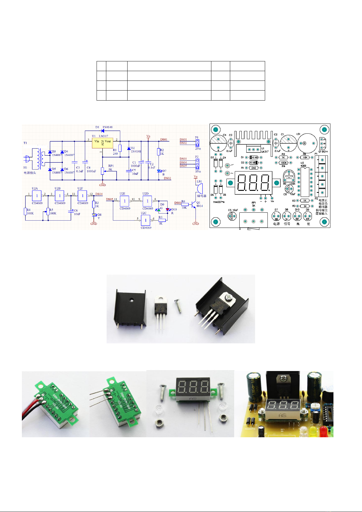
1. Schematic circuit diagram and component installation drawing.
2. Install the short component first and then install the taller sized component. Pay attention to the positive and negative
electrode of electrolytic capacitor.
3. Installment of LM317.
4. Installment of voltmeter: Take out three wires; weld three pieces of component pins; Install the voltmeter on the circuit
board with M3 screws and transparent spacers.
power connector
transformer
buzzer
Signal output frequency
Rectification
Rectification


