Banner DF-G2 High Speed Expert User manual

DF-G2 High Speed Expert™Dual
Display Fiber Amplifier
Instruction Manual
Original Instructions
177899 Rev. E
20 September 2016
©Banner Engineering Corp. All rights reserved
177899

Contents
1 Product Description ........................................................................................................ 3
1.1 Models ....................................................................................................................................3
1.2 Overview ................................................................................................................................ 4
1.3 Top Panel Interface ................................................................................................................... 4
2 Installation Instructions ................................................................................................5
2.1 Mounting Instructions ...............................................................................................................5
2.2 Installing the Fibers ..................................................................................................................5
2.3 Fiber Adapters .........................................................................................................................6
2.4 Wiring Diagrams ...................................................................................................................... 6
3 Operating Instructions .................................................................................................. 7
3.1 Run Mode ............................................................................................................................... 7
3.2 Program Mode .........................................................................................................................7
3.2.1 TEACH Selection .............................................................................................................8
3.2.2 Response Speed .............................................................................................................9
3.2.3 Offset Percent ................................................................................................................9
3.2.4 Auto Thresholds ............................................................................................................. 9
3.2.5 Delays/Timers ..............................................................................................................10
3.2.6 Gain Selection ..............................................................................................................10
3.2.7 Factory Defaults ........................................................................................................... 10
3.3 Remote Input ......................................................................................................................... 10
3.4 Adjust Mode .......................................................................................................................... 12
3.4.1 Two-Point TEACH ...........................................................................................................12
3.4.2 Dynamic TEACH ............................................................................................................ 13
3.4.3 Window SET ..................................................................................................................15
3.4.4 Light SET ......................................................................................................................17
3.4.5 Dark SET .....................................................................................................................18
3.4.6 Calibration SET ..............................................................................................................20
3.4.7 Troubleshooting ............................................................................................................21
4 Specifications .............................................................................................................. 23
4.1 Excess Gain Curves ................................................................................................................ 24
4.2 Beam Patterns ........................................................................................................................26
4.3 Dimensions ............................................................................................................................ 28
5 Accessories ..................................................................................................................29
5.1 Quick-Disconnect Cordsets ...................................................................................................... 29
6 Banner Engineering Corp. Limited Warranty ................................................................31
DF-G2 High Speed Expert™Dual Display Fiber Amplifier

1 Product Description
Advanced sensor with dual digital displays for use with plastic and glass fiber optic assemblies
• Best in class response speeds of: 10 µs, 15 µs, 50 µs, 250 µs, 500 µs, 1000 µs and
2000 µs allow the operator to optimize for fast response, long distance
applications, or noisy environments.
• Outstanding color contrast sensitivity; detects 32 levels of gray scale from black to
white
• Choose from IR or one of 4 visible beam colors: red, blue, green and white.
Depending on the beam color and fiber, the sensor reliably detects the toughest
color mark contrasts
• Easy to read dual digital displays show both signal level and threshold
simultaneously
• Lever action fiber clamp provides stable, reliable, and trouble-free fiber clamping
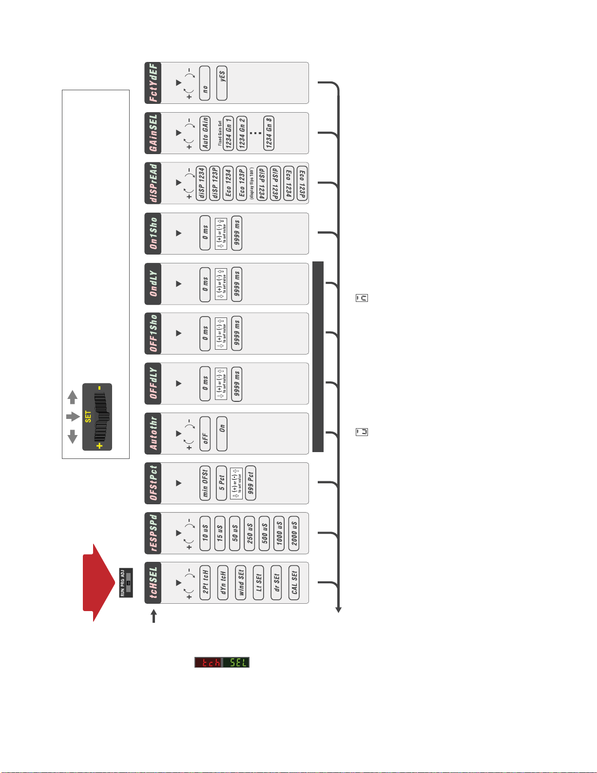
• Simple user interface ensures easy sensor set-up and programming via displays
and switches/buttons or remote input teach wire
•Expert TEACH and SET methods ensure optimal gain and threshold for all
applications, especially for high speed or low contrast applications
• User has full control over all operating parameters: threshold, Light Operate or
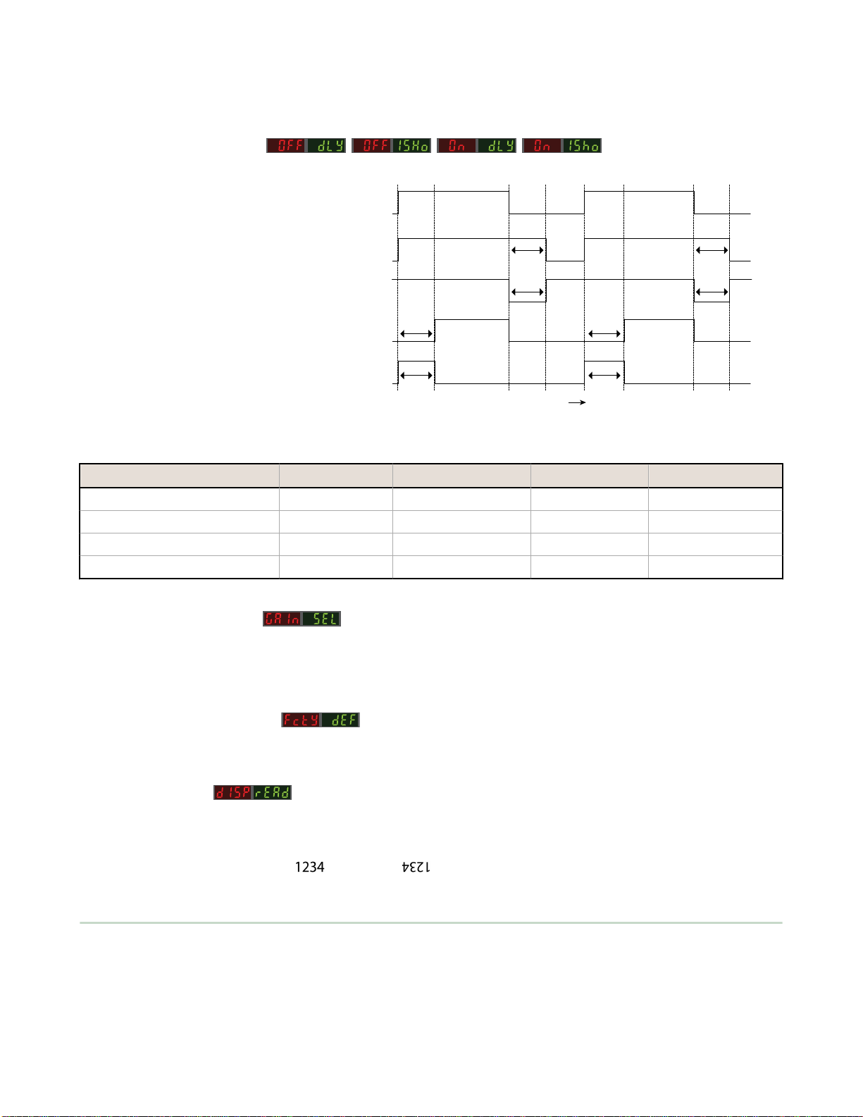
Dark Operate, output timing functions, gain level, and response speed
• Thermally stable electronics shorten start-up time and maintain signal stability
during operation
• ECO (economy) display mode reduces amplifier power consumption by 25%
• Cross talk avoidance algorithm allows two sensors to operate in close proximity for
many applications
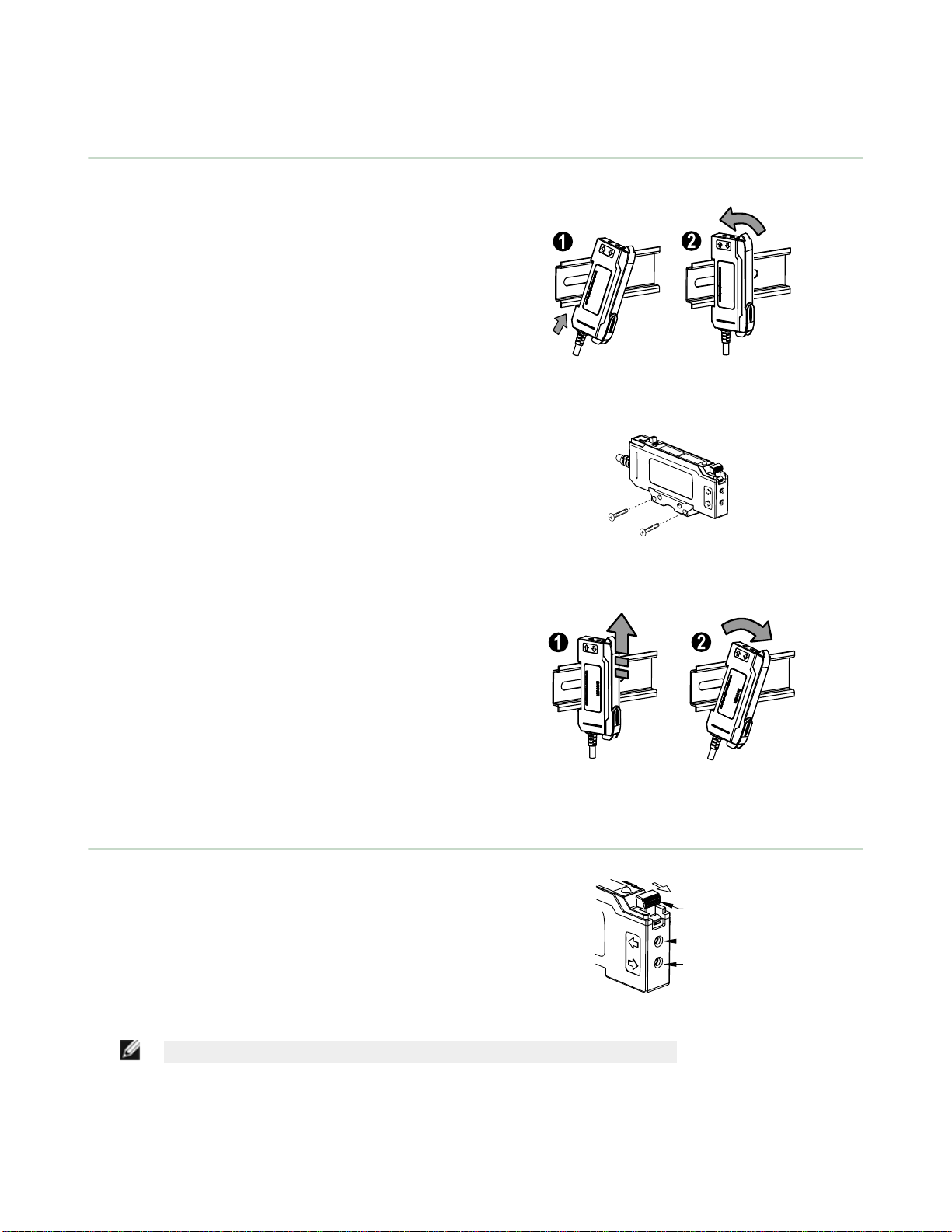
• Sleek 10 mm wide housing mounts to 35 mm DIN rail
WARNING: Not To Be Used for Personnel Protection
Never use this device as a sensing device for personnel protection. Doing so could lead to
serious injury or death. This device does not include the self-checking redundant circuitry necessary
to allow its use in personnel safety applications. A sensor failure or malfunction can cause either an
energized or de-energized sensor output condition.
1.1 Models
Model Sensing Beam Color Reference Sensing Range1Outputs Connector2
DF-G2-NS-2M Visible Red 1100 mm Single NPN
2 m (6.5 ft) cable, 4-wire
DF-G2-PS-2M Single PNP
DF-G2W-NS-2M Broad Spectrum White 550 mm Single NPN
DF-G2W-PS-2M Single PNP
DF-G2G-NS-2M Visible Green 660 mm Single NPN
DF-G2G-PS-2M Single PNP
DF-G2B-NS-2M Visible Blue 770 mm Single NPN
DF-G2B-PS-2M Single PNP
DF-G2IR-NS-2M Infrared 2100 mm Single NPN
DF-G2IR-PS-2M Single PNP
1Excess gain = 1, Long Range response speed, opposed mode sensing. PIT46U plastic fiber used for visible LED models, IT.83.3ST5M6 glass fiber
used for IR model
2Connector options:
• A model with a QD connector requires a mating cordset (see Quick-Disconnect Cordsets on page 29)
• For 9 m cable, change the suffix 2M to 9M in the 2 m model number (example, DF-G2-NS-9M)
• For 150 mm (6 in) PVC pigtail, M8 Pico QD connector, 4-pin change the suffix 2M to Q3 in the 2 m model number (example, DF-G2-NS-
Q3)
• For 150 mm (6 in) PVC pigtail, M12 Euro QD connector, 4-pin change the suffix 2M to Q5 in the 2 m model number (example, DF-G2-
NS-Q5)
• For integral M8 Pico QD connector, 4-pin change the suffix 2M to Q7 in the 2 m model number (example, DF-G2-NS-Q7)
DF-G2 High Speed Expert™Dual Display Fiber Amplifier
www.bannerengineering.com - Tel: 763.544.3164 3

1.2 Overview
The DF-G2 is an easy-to-use, DIN-rail-mountable fiber optic sensor with best in class response speed and repeatability. It
provides high-performance sensing in high speed or low contrast applications where fast response time is required.
The sensor’s compact housing has dual digital displays (Red/Green) and a bright output LED for easy programming and
status monitoring during operation. The sensor features a single discrete output, either NPN or PNP, by model.
The DF-G2 features improved temperature compensation compared with previous fiber optic sensors. An accessory clamp
is available to secure a bank of connected sensors together on a DIN rail (see Accessories on page 29).
Figure 1. DF-G2 Model Features
1Output LED
2LO/DO Switch
3RUN/PRG/ADJ Mode Switch
4Lever Action Fiber Clamp
5Red Signal Level
6Green Threshold
7+/SET/- Rocker Button
1.3 Top Panel Interface
Opening the dust cover provides access to the top panel interface. The top panel interface consists of the RUN/PRG/ADJ
mode switch, LO/DO switch, +/SET/- rocker button, dual red/green digital displays, and output LED.
RUN/PRG/ADJ Mode Switch
The RUN/PRG/ADJ mode switch puts the sensor in RUN, PRG (Program), or ADJ (Adjust) mode. RUN mode
allows the sensor to operate normally and prevents unintentional programming changes via the +/SET/-
button. PRG mode allows the sensor to be programmed through the display driven programming menu (see
Program Mode on page 7 ). ADJ mode allows the user to perform Expert TEACH/SET methods and
Manual Adjust (see Adjust Mode on page 12 ).
LO/DO Switch
The LO/DO switch is used to select Light Operate or Dark Operate mode. In Light Operate mode, the output
is ON when the sensing condition is above the threshold (for Window SET, the output is ON when the
sensing condition is inside the window). In Dark Operate mode, the output is ON when the sensing condition
is below the threshold (for Window SET, the output is ON when the sensing condition is outside the
window).
+/SET/- Rocker Button
The +/SET/- rocker button is a 3-way button. The +/- positions are engaged by rocking the button left/
right. The SET position is engaged by clicking down the button while the rocker is in the middle position. All
three button positions are used during PRG mode to navigate the display driven programming menu. During
ADJ mode, SET is used to perform TEACH/SET methods and +/- are used to manually adjust the
threshold(s). The rocker button is disabled during RUN mode, except when using Window SET, see Window
SET on page 15.
Red/Green Digital Displays
During RUN and ADJ mode, the Red display shows the signal level and the Green display shows the
threshold. During PRG mode, both displays are used to navigate the display driven programming menu.
Output LED
The output LED provides a visible indication when the output is activated.
DF-G2 High Speed Expert™Dual Display Fiber Amplifier
4 www.bannerengineering.com - Tel: 763.544.3164

2 Installation Instructions
2.1 Mounting Instructions
Mount on a DIN Rail
1. Hook the DIN rail clip on the bottom of the DF-G2
over the edge of the DIN rail (1).
2. Push the DF-G2 up on the DIN rail (1).
3. Pivot the DF-G2 onto the DIN rail, pressing until it
snaps into place (2).
Mount to the Accessory Bracket (SA-DIN-BRACKET)
1. Position the DF-G2 in the SA-DIN-BRACKET.
2. Insert the supplied M3 screws.
3. Tighten the screws.
Remove from a DIN rail
1. Push the DF-G2 up on the DIN rail (1).
2. Pivot the DF-G2 away from the DIN rail and remove
it (2).
2.2 Installing the Fibers
Follow these steps to install glass or plastic fibers.
1. Open the dust cover.
2. Move the fiber clamp forward to unlock it.
3. Insert the fiber(s) into the fiber port(s) until they
stop.
4. Move the fiber clamp backward to lock the fiber(s).
5. Close the dust cover.
Fiber Emitter
Port
Fiber Receiver
Fiber Clamp
Port
Move forward
to release the
fibers
NOTE: For optimum performance of IR models, if applicable, glass fibers must be used.
DF-G2 High Speed Expert™Dual Display Fiber Amplifier
www.bannerengineering.com - Tel: 763.544.3164 5

2.3 Fiber Adapters
NOTE: If a thin fiber with less than 2.2 mm outer diameter is used, install the fiber adapter provided with the fiber
assembly to ensure a reliable fit in the fiber holder. Align the fibers to the end of the adaptors. Banner includes the
adapters with all fiber assemblies.
TO
FIBERS
TO
SENSOR
Fiber Outer Diameter (mm) Adapter Color
Ø 1.0 Black
Ø 1.3 Red
Ø 2.2 No adapter needed
When connecting coaxial-type fiber assemblies to the amplifier, install the single-core (center) fiber to the Transmitter
port, and the multi-core (outer) fiber to the Receiver port. This will result in the most reliable detection.
TRANSMITTER
RECEIVER
Single-core fiber
Multi-core fiber
2.4 Wiring Diagrams
NPN Models
Remote
Programming
(N.O.)
10-30V dc
Load
PNP Models
Load
10–30 V dc
Remote
Programming
(N.O.)
Key
1 = Brown
2 = White
3 = Blue
4 = Black
NOTE: Open lead wires must be connected to a terminal block.
DF-G2 High Speed Expert™Dual Display Fiber Amplifier
6 www.bannerengineering.com - Tel: 763.544.3164

3 Operating Instructions
3.1 Run Mode
Run mode allows the sensor to operate normally and prevents unintentional programming changes. The +/SET/- rocker
button is disabled during RUN mode, except when using Window SET.
3.2 Program Mode
Program (PRG) mode allows the following settings to be programmed in the DF-G2 (refer to Program Mode Flowchart and
and Remote Input Flowchart for programming). See Factory Default Settings in Specifications.
DF-G2 High Speed Expert™Dual Display Fiber Amplifier
www.bannerengineering.com - Tel: 763.544.3164 7

To scroll through menu lists: Press “+” or “-”
To enter a choice list or to select and save: Click SET
To exit a choice list without saving: Press and hold SET for 2 seconds
Click SET
to enter choice list
Press and hold SET to exit
choice list without saving
DISPLAY
LOOP
Return to Menu List
PROGRAM MODE
Mode Switch
to “PRG”
Click SET
to enter choice list
DISPLAY
LOOP
Click SET
to enter choice list
Click SET
to enter choice list
DISPLAY
LOOP
Click SET
to enter choice list
Click SET
to enter choice list
Click SET
to enter choice list
Click SET
to enter choice list
Click SET
to enter choice list
DISPLAY
LOOP
Click SET
to enter choice list
DISPLAY
LOOP
Click SET
to enter choice list
DISPLAY
LOOP
rocker button
Click SET to select and save a choice in any list
Menu
List
on display represents a “w” on display represents a “m”
Figure 2.
3.2.1 TEACH Selection
The DF-G2 can be programmed for one of the following TEACH/SET methods:
• Two-Point TEACH
• Dynamic TEACH
DF-G2 High Speed Expert™Dual Display Fiber Amplifier
8 www.bannerengineering.com - Tel: 763.544.3164

• Window SET
• Light SET
• Dark SET
• Calibration SET
NOTE: A TEACH Selection must be selected by programming before TEACH/SET methods can be used.
3.2.2 Response Speed
The DF-G2 can be programmed for one of the following Response Speeds:
Response Speed Display Range Crosstalk Avoidance Algorithm
10 µs (Super High Speed) 0 – 4000 Disabled
15 µs (High Speed) 0 – 4000 Disabled
50 µs (Fast) 0 – 4000 Disabled
250 µs (Standard) 0 – 4000 Enabled
500 µs (Medium Range) 0 – 9999 Enabled
1000 µs (Long Range) 0 – 9999 Enabled
2000 µs (Long Range with immunity to
Energy Efficient Lights) 0 – 9999 Enabled
3.2.3 Offset Percent
The Offset Percent is used during the Window, Light, or Dark SET methods. The threshold(s) are positioned a
programmable % offset from the taught condition.
The allowable range depends upon the Response Speed Mode, as shown below:
Response Speed MIN % MAX %
10 µs 5 999
15 µs 5 999
50 µs 2 999
250 µs 2 999
500 µs 1 999
1000 µs 1 999
2000 µs 1 999
The offset percent can also be programmed to Minimum Offset. This allows the DF-G2 to set the
threshold(s) as close as possible to the presented condition, but still provide for reliable sensing.
NOTE: Offset Percent MUST be programmed to Minimum Offset for Dark SET to accept conditions of no signal (0
counts).
3.2.4 Auto Thresholds
Auto Thresholds can be programmed to be ON/OFF. The Auto Thresholds algorithm continuously tracks slow changes in
the taught condition(s), and optimizes the threshold(s) to provide for reliable sensing. For Two-Point and Dynamic TEACH,
the algorithm optimizes the threshold to be centered between the light and dark conditions. For Window, Light, and Dark
SET, the algorithm optimizes the threshold(s) to maintain the programmed Offset Percent from the taught condition.
• After programming Auto Thresholds to ON, it is highly recommended to re-perform the TEACH/SET method
• Manual Adjustments are disabled when Auto Thresholds are ON
• Auto Thresholds are automatically disabled in Calibration SET (see Calibration SET on page 20)
DF-G2 High Speed Expert™Dual Display Fiber Amplifier
www.bannerengineering.com - Tel: 763.544.3164 9

• Severe contamination/changes in the taught condition can prevent the Auto Thresholds algorithm from optimizing
the threshold(s). If this occurs, the DF-G2 enters a Threshold Alert or Threshold Error state. See
Troubleshooting on page 21 for more explanation.
3.2.5 Delays/Timers
ON/OFF Delays and ON/OFF One-Shot
timers can be programmed between 1 -
9999 ms (a value of 0 disables the delay/
timer). Figure 3 on page 10 defines how
the delays/timers affect the output
behavior.
Some combinations of delays/timers are not
allowed. The DF-G2 programming menu
automatically disables invalid combinations
of delays/timers. The following table shows
the allowable combinations of delays/
timers:
Output
OFF Delay
ON Delay
Time
OFF 1-Shot
ON 1-Shot
ON
OFF
D
D
D
D
D
D
D
D
(D = 1 - 9999 ms)
Figure 3. DF-G2 Delays/Timers
OFF Delay OFF One-Shot Timer ON Delay ON One-Shot Timer
OFF Delay - OK OK N/A
OFF One-Shot Timer OK - N/A N/A
ON Delay OK N/A - OK
ON One-Shot Timer N/A N/A OK -
3.2.6 Gain Selection
The DF-G2 can operate in Auto Gain mode or the Gain can be fixed to be in Gain 1...8. In Auto Gain, the DF-G2 optimizes
the gain during a TEACH/SET method for the presented condition(s). While viewing the fixed gains in the Gain Selection
choice list, the DF-G2 will automatically switch to the selected gain and display the measured signal on the Red display.
This allows for easy and quick evaluation of the fixed gain mode.
3.2.7 Factory Defaults
The Factory Defaults menu allows the DF-G2 to be easily restored back to original factory default settings (see Factory
Default Settings in Specifications).
Display Readout
The readout of the digital displays can be programmed for the following options:
• Signal/Threshold readout - Numeric (1234) or % (123P)
• ECO mode - Enabled or Disabled (ECO mode dims the displays to reduce current consumption)
• Display Orientation - Normal ( ) or Flipped ( )
3.3 Remote Input
The remote input may be used to perform TEACH/SET methods and to program the sensor remotely. Connect the white
input wire of the sensor to ground (0 V dc), with a remote switch connected between them. Pulse the remote input
according to the diagram shown in Figure 4 on page 11. Follow the instructions in the TEACH/SET sections in Adjust
Mode on page 12 to perform a TEACH/SET method.
The sensor exits TEACH and remote programming modes after a 60 second timeout. Users may exit TEACH and remote
programming modes by setting the remote input low for more than 2 seconds. In either case, the sensor returns to Run
mode without saving any new settings.
DF-G2 High Speed Expert™Dual Display Fiber Amplifier
10 www.bannerengineering.com - Tel: 763.544.3164

Remote
Input
1x
3x
4x
2x
1x
1x
4x
3x
2x
1x
5x
6x
4x
3x
2x
1x
3x
5x
6x
4x
3x
2x
1x
4x
2x
1x
5x
5x
6x
4x
3x
2x
1x
7x
8x
10 µs (High-Speed)
15 µs (Standard)
50 µs (Long Range)
250 µs (Standard Speed)
500 µs (Medium Range)
1000 µs (Long Range)
2000 µs
2 Pt. TEACH
Dynamic TEACH
Window SET
Light SET
Dark SET
CAL SET
Min. Offset
2% *
5%
10%
20%
50%
Button Unlock (uloc)
Button Lock (loc)
Numeric
Percent
Numeric Flipped
Percent Flipped
ECO Numeric
ECO Percent
ECO Numeric Flipped
ECO Percent Flipped
PRO Basic
PRO Advanced
3x PRO Advanced
(continued at top)
(continued from below)
Button Lock (loc) or Unlock (uloc)
8x Factory Default Settings
2x
1x
2x
1x
5x
6x
4x
3x
2x
1x
3x
5x
6x
4x
3x
2x
1x
Auto Thresholds ON
Auto Thresholds OFF
0 ms
2 ms
5 ms
10 ms
20 ms
50 ms
0 ms
2 ms
5 ms
10 ms
20 ms
50 ms
4x
5x
6x
4x
3x
2x
1x
5x
5x
6x
4x
3x
2x
1x
0 ms
2 ms
5 ms
10 ms
20 ms
50 ms
0 ms
2 ms
5 ms
10 ms
20 ms
50 ms
6x
5x
6x
4x
3x
2x
1x Auto Gain
Gain 1
Gain 2
Gain 3
Gain 4
Gain 5
8x
9x
7x Gain 6
Gain 7
Gain 8
Two Point TEACH 2Pt tch, then 1234 2nd
PASS or FAIL (with % Minimum Diff.)
1x
1x
Dynamic TEACH dYn tch, then 1234 dYn
PASS or FAIL (with % Minimum Diff.)
1x Light SET Lt SEt then PASS or FAIL*
1x Dark SET dr SEt then PASS or FAIL*
1x Window SET wind SEt then PASS or FAIL*
1x Calibration SET CAL SET then PASS or FAIL
TEACH METHODS
PROGRAM (Basic)
PROGRAM (Advanced)
* with % offset if not hard fail
Response Speed
TEACH Selection
Offset Percent
Button Lock
Display Readout
Auto Thresholds
Off Delay
Off One-Shot
On Delay
On One-Shot
Gain Select
0.04 seconds < T < 0.8 seconds
Timing between Pulse groups > 1 second
Pulse Timing (T)
or
NOTE: Follow procedure for the selected TEACH/SET method
(highlighted in black box) chosen in the TEACH Selection menu
2x
In Super High-Speed and High-Speed Responses, 2% offset is forced to Min. Offset
*
5x
6x
7x (Long Range with
immunity to energy-
efficient lights)
Figure 4. Remote Input Flowchart
DF-G2 High Speed Expert™Dual Display Fiber Amplifier
www.bannerengineering.com - Tel: 763.544.3164 11

3.4 Adjust Mode
Sliding the RUN/PRG/ADJ mode switch to the ADJ position allows the user to perform Expert TEACH/SET methods and
Manual Adjustment of the threshold(s).
3.4.1 Two-Point TEACH
• Establishes a single switching threshold
• Threshold can be adjusted by using the "+" and "-" rocker button (Manual Adjust)
Two-Point TEACH is used when two conditions can be presented statically to the sensor. The sensor locates a single
sensing threshold (the switch point) midway between the two taught conditions, with the Output ON condition on one side,
and the Output OFF condition on the other.
Sensor positions
threshold midway
between taught conditions
Darkest
(no signal)
Most Light
(saturated
signal)
Output OFF Output ON
Darkest Taught
Condition
Lightest Taught
Condition
Position
adjusted by
Manual Adjust
Figure 5. Two-Point TEACH (Light Operate shown)
The Output ON and OFF conditions can be reversed by using the LO/DO (Light Operate/ Dark Operate) switch.
Two-Point TEACH and Manual Adjust
Moves switching threshold value up or down to make adjustments
• Slide Mode switch to ADJ to enter Adjust mode
• Press "+" to increase; press "-" to decrease
◦GREEN display shows the switching threshold value
◦2 seconds after adjustment, the GREEN display will flash 3 times to confirm
• Slide Mode switch to RUN to complete operation
Remember: Manual adjustments are disabled when Auto Thresholds are ON
Follow these steps to perform a Two-Point TEACH:
Note: TEACH Selection must be programmed to 2Pt tcH.
1. Enter Adjust mode.
Method Action Result
SET Button 3Set the Mode switch to ADJ. Display: Red - Signal Level; Green -
Threshold
Remote Input 4No action is required; sensor is ready
for the Two-Point TEACH method
2. Teach the first condition.
3SET Button: 0.04 seconds ≤"Click" ≤0.8 seconds
4Remote Input: 0.04 seconds ≤T ≤0.8 seconds
DF-G2 High Speed Expert™Dual Display Fiber Amplifier
12 www.bannerengineering.com - Tel: 763.544.3164

Method Action Result
SET Button a. Present the first condition.
b. Click the SET rocker button.
Display: Flashes "2Pt tch" then holds
on "1234 2nd"
Remote Input a. Present the first condition.
b. Single-pulse the remote input.
T
3. Teach the second condition.
Method Action Result
SET Button a. Present the second condition.
b. Click the SET rocker button.
TEACH Accepted
Displays alternate "PASS" and %
Minimum Difference5; Sensor returns
to Adjust mode
TEACH Not Accepted
Displays alternate "FAIL" and %
Minimum Difference5; Sensor returns
to Adjust mode
Remote Input a. Present the second condition.
b. Single-pulse the remote input.
T
4. Return to Run mode.
Method Action Result
SET Button Move the Mode switch to RUN Display: Red - Signal Level; Green -
Threshold
Remote Input No action is required; sensor returns to
RUN mode automatically
3.4.2 Dynamic TEACH
• Teaches on-the-fly
• Establishes a single switching threshold
• Threshold can be adjusted using "+" and "-" rocker button (Manual Adjust)
Dynamic TEACH is best used when a machine or process may not be stopped for teaching. The sensor learns during actual
sensing conditions, taking multiple samples of the light and dark conditions and automatically setting the threshold at the
optimum level.
5See Troubleshooting on page 21 for more explanation of the % Minimum Difference displayed after the Two-Point TEACH
method.
DF-G2 High Speed Expert™Dual Display Fiber Amplifier
www.bannerengineering.com - Tel: 763.544.3164 13

Sensor positions
threshold midway
between taught conditions
Darkest
(no signal)
Most Light
(saturated
signal)
Output OFF Output ON
Darkest Taught
Condition
Lightest Taught
Condition
Position
adjusted by
Manual Adjust
Figure 6. Dynamic TEACH (Light Operate shown)
The output ON and OFF conditions can be reversed using the LO/DO switch.
Dynamic TEACH and Manual Adjust
Moves switching threshold value up or down to make adjustments
• Slide Mode switch to ADJ to enter Adjust mode
• Press "+" to increase; press "-" to decrease
◦GREEN display shows the switching threshold value
◦2 seconds after adjustment, GREEN display will flash 3 times to confirm
• Slide Mode switch to RUN to complete operation
Remember: Manual adjustments are disabled when Auto Thresholds are ON
Follow these steps to perform Dynamic TEACH:
NOTE: TEACH Selection must be programmed to dYn tcH.
1. Enter Adjust Mode.
Method Action Result
SET Button 6Set Mode switch to ADJ Display: Red - Signal Level; Green -
Threshold
Remote Input 7No action required; sensor is ready for
Dynamic TEACH method
2. Enter Dynamic TEACH.
Method Action Result
SET Button Click the SET rocker button Display: Flashes "dYn tch" then holds
on "1234 dYn"
Remote Input Single-pulse remote input
T
3. Present ON and OFF Conditions.
Method Action Result
SET Button Present ON and OFF conditions Display: Red - Signal Level; Green -
Threshold
Remote Input Present ON and OFF conditions
6SET Button: 0.04 seconds ≤"Click" ≤0.8 seconds
7Remote Input: 0.04 seconds ≤T ≤0.8 seconds
DF-G2 High Speed Expert™Dual Display Fiber Amplifier
14 www.bannerengineering.com - Tel: 763.544.3164

4. Exit Dynamic TEACH.
Method Action Result
SET Button Click the SET rocker button TEACH Accepted
Displays alternate "PASS" with %
Minimum Difference8, Sensor returns
to Adjust mode
TEACH Not Accepted
Displays alternate "FAIL" with %
Minimum Difference8, Sensor returns
to Adjust mode
Remote Input Single-pulse remote input
T
5. Return to RUN Mode.
Method Action Result
SET Button Move Mode switch to RUN Display: Red - Signal Level; Green -
Threshold
Remote Input No action required; sensor returns to
RUN mode automatically
3.4.3 Window SET
• Sets window thresholds that extend a programmable % offset above and below the presented condition
• All other conditions (lighter or darker) cause the output to change state
• Sensing window center can be adjusted using "+" and "-" rocker button (Manual Adjust)
• Recommended for applications where a product may not always appear in the same place, or when other signals
may appear
• See Program Mode for programming the Offset Percent setting
A single sensing condition is presented, and the sensor positions window thresholds a programmable % offset above and
below the presented condition. In LO mode, Window SET designates a sensing window with the Output ON condition inside
the window, and the Output OFF conditions outside the window.
Sensor positions
window thresholds
a programmable %
offset from the
presented condition
Darkest
(no signal)
Most Light
(saturated
signal)
Condition
Presented
Sensing window
center adjusted by
Manual Adjust
Output OFF Output OFFOutput ON
Figure 7. Window SET (Light Operate shown)
Output ON and OFF conditions can be reversed using the LO/DO switch.
8See Troubleshooting on page 21 for more explanation of the % Minimum Difference displayed after the Dynamic TEACH
method.
DF-G2 High Speed Expert™Dual Display Fiber Amplifier
www.bannerengineering.com - Tel: 763.544.3164 15

Window SET and Manual Adjust
Moves sensing window center value up or down to make adjustments
• Slide Mode switch to ADJ to enter Adjust mode
• Press "+" to increase; press "-" to decrease
◦GREEN display shows the sensing window center value
◦2 seconds after adjustment, the GREEN display will flash 3 times to confirm
• Slide Mode switch to RUN to complete operation
Remember: Manual adjustments are disabled when Auto Thresholds are ON
Follow these steps to perform a Window SET:
Note: TEACH Selection must be programmed to wind SEt.
1. Enter Adjust Mode
Method Action Result
SET Button 9Set Mode switch to ADJ Display: Red - Signal Level; Green -
Threshold
Remote Input 10 No action required; sensor is ready for
Window SET method
2. SET Sensing Condition
Method Action Result
SET Button • Present sensing condition
• Click the SET rocker button Threshold Condition Accepted
Displays read "wInd SEt" then
alternate "PASS" with % Offset11;
Sensor returns to Adjust mode
Threshold Condition Not Accepted
Displays read "wInd SEt" then
alternate "FAIL" with minimum %
Offset11 for sensing condition; Sensor
returns to Adjust mode
Remote Input • Present sensing condition
• Single-pulse the remote input
T
3. Return to RUN Mode
Method Action Result
SET Button Move Mode switch to Run Display: Red - Signal Level; Green -
Window Center (see Figure 8 on page
17 for instructions on how to display
upper and lower thresholds)
Remote Input No action required; sensor returns to
Run mode automatically
9SET Button: 0.04 seconds ≤"Click" ≤0.8 seconds
10 Remote Input: 0.04 seconds ≤T ≤0.8 seconds
11 See Troubleshooting on page 21 for more explanation of the % Offset displayed after the Window SET method
DF-G2 High Speed Expert™Dual Display Fiber Amplifier
16 www.bannerengineering.com - Tel: 763.544.3164

Window SET (during RUN mode)
Upon sensor power-up, Window Center is displayed
Upper
Threshold
Displayed
Window
Center
Displayed
Lower
Threshold
Displayed
Figure 8. Upper and Lower Thresholds
3.4.4 Light SET
• Sets a threshold a programmable % offset below the presented condition
• Changes output state on any condition darker than the threshold condition
• Threshold can be adjusted using "+" and "-" rocker button (Manual Adjust)
• Recommended for applications where only one condition is known, for example a stable light background with
varying darker targets
• See Program Mode for programming the Offset Percent setting
A single sensing condition is presented, and the sensor positions a threshold a programmable % offset below the
presented condition. When a condition darker than the threshold is sensed, the output either turns ON or OFF, depending
on the LO/DO setting.
Threshold position
adjusted by
Manual Adjust
Sensor positions
threshold a programmable
% offset below the
presented condition
Darkest
(no signal)
Most Light
(saturated
signal)
Output OFF Output ON
Condition
Presented
Figure 9. Light SET (Light Operate shown)
Light SET and Manual Adjust
Moves switching threshold value up or down to make adjustments
• Slide Mode switch to ADJ to enter Adjust mode
• Press "+" to increase; press "-" to decrease
◦GREEN display shows the switching threshold value
◦2 seconds after adjustment, the GREEN display will flash 3 times to confirm
• Slide Mode switch to RUN to complete operation
Remember: Manual adjustments are disabled when Auto Thresholds are ON
Follow these steps to perform a Light SET:
Note: TEACH Selection must be programmed to Lt SEt.
1. Enter Adjust Mode
DF-G2 High Speed Expert™Dual Display Fiber Amplifier
www.bannerengineering.com - Tel: 763.544.3164 17

Method Action Result
SET Button 12 Set Mode switch to ADJ Display: Red - Signal Level; Green -
Threshold
Remote Input 13 No action is required; sensor is ready
for Light SET method
2. SET Sensing Condition
Method Action Result
SET Button • Present sensing condition
• Click the SET rocker button Threshold Condition Accepted
Displays read "Lt SEt" then alternate
"PASS" with % Offset14; Sensor
returns to Adjust mode
Threshold Condition Not Accepted
Displays read "Lt SEt" then alternate
"FAIL" with minimum % Offset14 for
sensing condition; Sensor returns to
Adjust mode
Remote Input • Present sensing condition
• Single-pulse the remote input
T
3. Return to RUN Mode
Method Action Result
SET Button Move Mode switch to RUN Display: Red - Signal Level; Green -
Threshold
Remote Input No action required; sensor returns to
RUN mode automatically
3.4.5 Dark SET
• Sets a threshold a programmable % offset above the presented condition
• Any condition lighter than the threshold condition causes the output to change state
• Threshold can be adjusted using "+" and "-" rocker button (Manual Adjust)
• Recommended for applications where only one condition is known, for example a stable dark background with
varying lighter targets
• See Program Mode for programming the Offset Percent setting
NOTE: Offset Percent MUST be programmed to Minimum Offset to accept conditions of no signal (0 counts).
A single sensing condition is presented, and the sensor positions a threshold a programmable % offset above the
presented condition. When a condition lighter than the threshold is sensed, the output either turns ON or OFF, depending
on the LO/DO setting.
12 SET Button: 0.04 seconds ≤"Click" ≤0.8 seconds
13 Remote Input: 0.04 seconds ≤T ≤0.8 seconds
14 See Troubleshooting on page 21 for more explanation of the % Offset displayed after the Light SET method
DF-G2 High Speed Expert™Dual Display Fiber Amplifier
18 www.bannerengineering.com - Tel: 763.544.3164

Sensor positions
threshold a programmable
% offset above the
presented condition
Threshold position
adjusted by
Manual Adjust
Darkest
(no signal)
Most Light
(saturated
signal)
Output OFF Output ON
Condition
Presented
Figure 10. Dark SET (Light Operate shown)
Dark SET and Manual Adjust
Moves switching threshold value up or down to make adjustments
• Slide Mode switch to ADJ to enter Adjust mode
• Press "+" to increase; press "-" to decrease
◦GREEN display shows the switching threshold value
◦2 seconds after adjustment, the GREEN display will flash 3 times to confirm
• Slide Mode switch to RUN to complete operation
Remember: Manual adjustments are disabled when Auto Thresholds are ON
Follow these steps to perform a Dark SET:
Note: TEACH Selection must be programmed to dr SEt.
1. Enter Adjust Mode.
Method Action Result
SET Button 15 Set Mode switch to ADJ Display: Red - Signal Level; Green -
Threshold
Remote Input 16 No action required; sensor is ready for
Dark SET method
2. SET Sensing Condition.
Method Action Result
SET Button • Present sensing condition
• Click the SET rocker button Threshold Condition Accepted
Displays read "dr SEt" then alternate
"PASS" with % Offset17; Sensor
returns to Adjust mode
Threshold Condition Not Accepted
Displays read "dr SEt" then alternate
"FAIL" with minimum % Offset17 for
sensing condition; Sensor returns to
Adjust mode
Remote Input • Present sensing condition
• Single-pulse the remote input
T
15 SET Button: 0.04 seconds ≤"Click" ≤0.8 seconds
16 Remote Input: 0.04 seconds ≤T ≤0.8 seconds
17 See Troubleshooting on page 21 for more explanation of the % Offset displayed after the Dark SET method
DF-G2 High Speed Expert™Dual Display Fiber Amplifier
www.bannerengineering.com - Tel: 763.544.3164 19

3. Return to RUN Mode.
Method Action Result
SET Button Move Mode switch to RUN Display: Red - Signal Level; Green -
Threshold
Remote Input No action required; sensor returns to
RUN mode automatically
3.4.6 Calibration SET
• Sets a threshold exactly at the presented condition
• Threshold can be adjusted using "+" and "-" rocker button (Manual Adjust)
A single sensing condition is presented, and the sensor positions a threshold exactly at the presented condition. When a
condition lighter than the threshold is sensed, the output either turns ON or OFF, depending on the LO/DO setting.
Sensor positions
threshold exactly at
the presented condition
Threshold position
adjusted by
Manual Adjust
Darkest
(no signal)
Most Light
(saturated
signal)
Output OFF Output ON
Condition
Presented
Figure 11. Calibration SET (Light Operate shown)
Calibration SET and Manual Adjust
Moves switching threshold value up or down to make adjustments
• Slide Mode switch to ADJ to enter Adjust mode
• Press "+" to increase; press "-" to decrease
◦GREEN display shows the switching threshold value
◦2 seconds after adjustment, the GREEN display will flash 3 times to confirm
• Slide Mode switch to RUN to complete operation
Remember: Auto Thresholding is automatically disabled in Calibration SET
Follow these steps to perform a Calibration SET:
Note: TEACH Selection must be programmed to CAL SEt.
1. Enter Adjust Mode
Method Action Result
SET Button 18 • Set Mode switch to ADJ Display: Red - Signal Level; Green -
Threshold
Remote Input 19 No action required; sensor is ready for
Calibration SET method
2. SET Sensing Condition
18 SET Button: 0.04 seconds ≤"Click" ≤0.8 seconds
19 Remote Input: 0.04 seconds ≤T ≤0.8 seconds
DF-G2 High Speed Expert™Dual Display Fiber Amplifier
20 www.bannerengineering.com - Tel: 763.544.3164
Other manuals for DF-G2 High Speed Expert
1
This manual suits for next models
10
Table of contents
Other Banner Amplifier manuals

Banner
Banner DF-G3 Series User manual

Banner
Banner DF-G1 Expert User manual

Banner
Banner Expert DF-G1-NS-2M User manual

Banner
Banner PICO-AMP MD14BB6 User manual

Banner
Banner DF-G2 Series User manual

Banner
Banner DF-G3 Long Range Expert User manual

Banner
Banner DF-G3 Long Range Expert User manual

Banner
Banner PL3-M User manual

Banner
Banner MA3-4 User manual

Banner
Banner DF-G1-NS-2M User manual