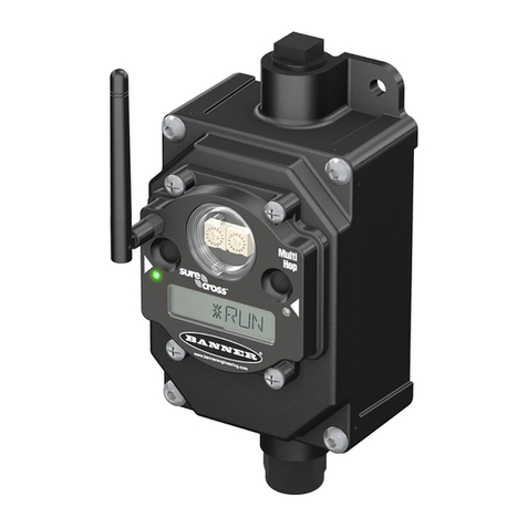
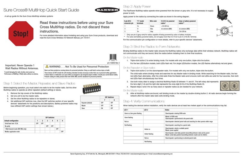
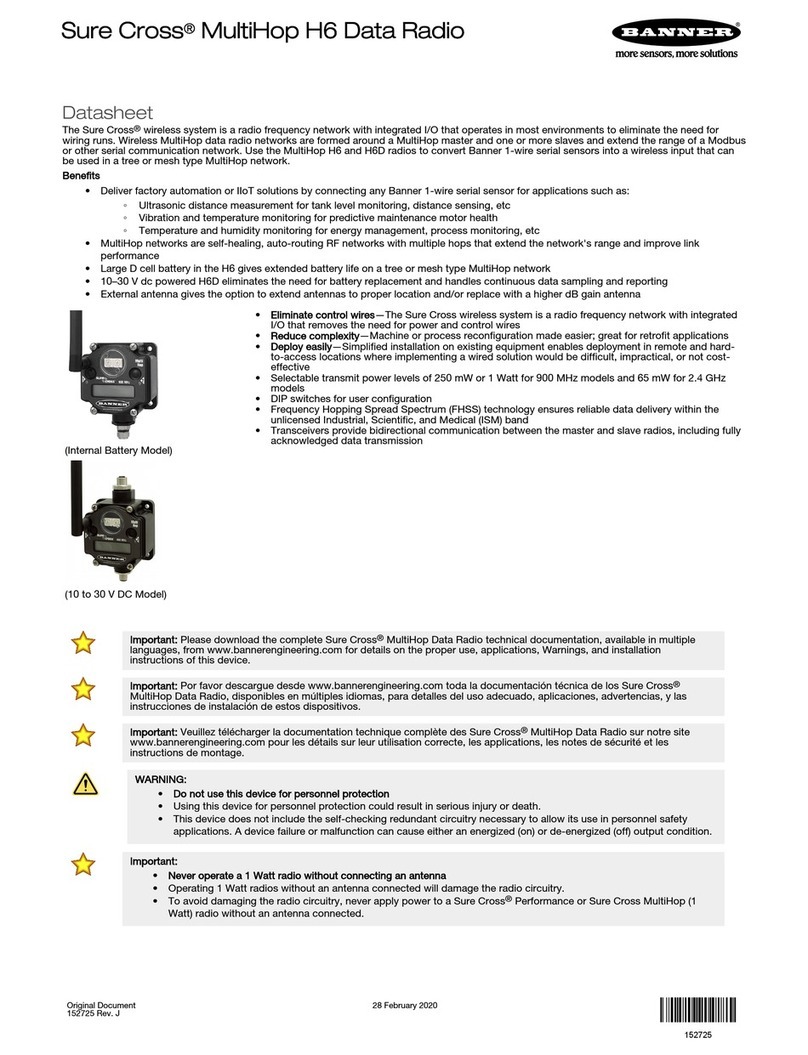
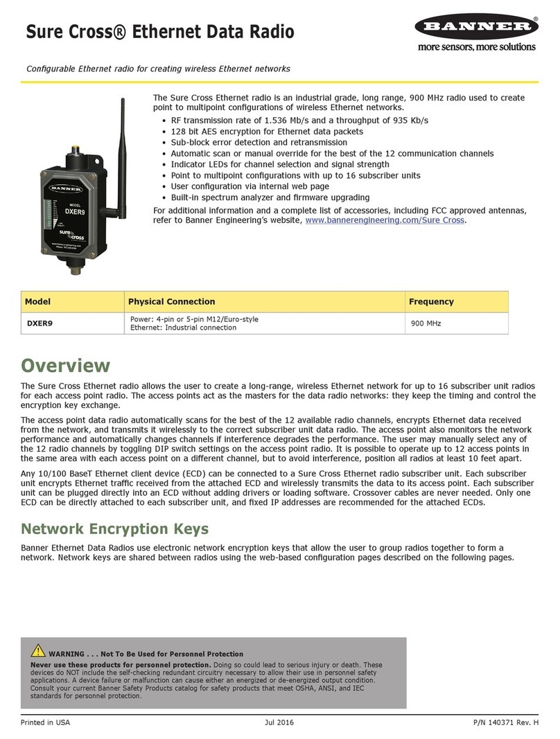
Banner Sure Cross DX80 User manual

Quick Start Guide
Read these instructions before using your Sure Cross radios. Do not discard these instructions. For more detailed information
about installing and using your Sure Cross products, download and read the instruction manual: Sure Cross MultiHop Radio
Instruction Manual (p/n
151317
).
WARNING: Not To Be Used for Personnel Protection
Never use this device as a sensing device for personnel protection. Doing so could lead to serious injury or
death. This device does not include the self-checking redundant circuitry necessary to allow its use in
personnel safety applications. A sensor failure or malfunction can cause either an energized or de-energized
sensor output condition.
CAUTION: Never Operate 1 Watt Radios Without Antennas
To avoid damaging the radio circuitry, never power up Sure Cross®Performance or Sure Cross MultiHop (1
Watt) radios without an antenna.
Setting Up Your MultiHop Network
To set up and install your wireless MultiHop network, follow these steps:
1. If your radios have DIP switches, configure the DIP switches of all devices. For DIP switch configurations, refer to the
product's datasheet.
2. Connect the sensors to the MultiHop radios if applicable. For available I/O, refer to the product's datasheet.
3. Apply power to all devices.
4. If your MultiHop radio has rotary dials, set the MultiHop Radio (Slave) ID. If your MultiHop radio has no rotary dials,
continue to the next step.
5. Form the wireless network by binding the slave and repeater radios to the master radio.
6. Observe the LED behavior to verify the devices are communicating with each other.
7. Configure any I/O points to use the sensors connected to the Sure Cross devices.
8. Conduct a site survey between the MultiHop radios.
9. Install your wireless sensor network components.
For additional information, refer to one of the following documents:
• MultiHop Data Radio Instruction Manual:
151317
• MultiHop Register Guide (End User Edition):
155289
Configure the DIP Switches for Master, Repeater, or Slave Mode
Before beginning operation, select one radio to be the master radio. Set the other MultiHop radios to operate as either repeaters
(default setting) or slaves.
1. Remove the top covers of the MultiHop radios.
2. Set one unit to be the master radio.
3. Set the other MultiHop radios to be repeaters or slaves.
4. Set additional DIP switches now.
(See the DIP switches section of your specific devices’ datasheets for the positions and descriptions. Battery-powered
radios may have different DIP switch settings than shown below.)
Device Settings
Switches
1 2 3 4 5 6 7 8
Serial line baud rate 19200 OR User defined receiver slots OFF ¹ OFF ¹
Parity: None OFF ¹ OFF ¹
Transmit power
900 MHz radios: 1.00 Watt (30 dBm)
2.4 GHz radios: 0.065 Watts (18 dBm) and 60 ms
frame
OFF ¹
Application mode: Modbus OFF ¹
Sure Cross®MultiHop Radio Quick Start Guide
Original Document
152653 Rev. C
8 May 2018
152653

Device Settings
Switches
1 2 3 4 5 6 7 8
MultiHop radio setting: Repeater OFF ¹ OFF ¹
MultiHop radio setting: Master OFF ON
MultiHop radio setting: Slave ON ² OFF ²
MultiHop radio setting: Reserved ON ON
¹ Default configuration
² Default configuration for the E housing models only
Apply Power to the MultiHop Radio
Connecting power to the communication pins will cause permanent damage. For
Flex
Power devices, do not apply more than 5.5 V
to the gray wire. The FlexPower Multihop radios will operate equally well when powered from the brown or gray wire. It is not
necessary to supply both. The power for the sensors can be supplied by the radio's SPx terminals or from the 10 V dc to 30 V dc
used to power the radio.
Pin Wire Color Models powered by 10 to 30
V dc with RS-485
FlexPower models with
RS-485
FlexPower models with
RS-232
1
4
5
3
2
1 brown 10 V dc to 30 V dc 10 V dc to 30 V dc 10 V dc to 30 V dc
2 white RS-485 / D1 / B / + RS-485 / D1 / B / + RS-232 Tx
3 blue dc common (GND) dc common (GND) dc common (GND)
4 black RS-485 / D0 / A / - RS-485 / D0 / A / - RS-232 Rx
5 gray - 3.6 V dc to 5.5 V dc 3.6 V dc to 5.5 V dc
Bind the MultiHop Radios to Form Networks
To create your MultiHop network, bind the repeater and slave radios to the designated master radio.
1. Apply power to all MultiHop radios and place the MultiHop radios configured as slaves or repeaters at least two meters
away from the master radio.
2. Put the MultiHop master radio into binding mode.
• For two button master radios, triple-click button 2.
• For one button master radios, triple-click the button.
For the two LED/button models, both LEDs flash red and the LCD shows *BINDNG and *MASTER. For single LED/button
models, the LED flashes alternatively red and green.
3. Put the MultiHop repeater or slave radio into binding mode.
• For two button radios, triple-click button 2.
• For one button radios, triple-click the button.
The child radio enters binding mode and searches for any Master radio in binding mode. While searching for the Master
radio, the two red LEDs flash alternately. When the child radio finds the Master radio and is bound, both red LEDs are solid
for four seconds, then both red LEDs flash simultaneously four times. For M-GAGE Nodes, both colors of the single LED
are solid (looks orange), then flash. After the slave/repeater receives the binding code transmitted by the master, the slave
and repeater radios automatically exit binding mode.
4. Repeat step 3 for as many slave or repeater radios as are needed for your network.
5. When all MultiHop radios are bound, exit binding mode on the master.
• For two button master radios, double-click button 2.
• For one button master radios, double-click the button.
All radio devices begin to form the network after the master data radio exits binding mode.
Child Radios Synchronize to the Parent Radios
The synchronization process enables a SureCross radio to join a wireless network formed by a master radio. After power-up,
synchronization may take a few minutes to complete. First, all radios within range of the master data radio wirelessly synchronize
to the master radio. These radios may be slave radios or repeater radios.
Sure Cross®MultiHop Radio Quick Start Guide
2 www.bannerengineering.com - Tel: +1-763-544-3164 P/N 152653 Rev. C

After repeater radios are synchronized to the master radio, any radios that are not in sync with the master but can "hear" the
repeater radio will synchronize to the repeater radios. Each repeater “family” that forms a wireless network path creates another
layer of synchronization process. The table below details the process of synchronization with a parent. When testing the devices
before installation, verify the radio devices are at least two meters apart or the communications may fail.
Slave and Repeater LED Behavior
All bound radios set to slave or repeater modes follow this LED behavior after powering up.
Two Button/LED Models Single Button/LED Models
Process
Steps
Response LED 1 LED 2 LED
1 Power is supplied to the radio. - Solid amber (briefly) Solid amber
2 The slave/repeater searches for a parent device. Flashes red - Flashes red (1 per 3 sec)
3 A parent device is detected. The slave/repeater searches for other
parent radios within range.
Solid red - Solid red
4 The slave/repeater selects a suitable parent. - Solid amber Solid amber
5 The slave/repeater attempts to synchronize to the selected parent. - Solid red Solid red
6 The slave/repeater is synchronized to the parent. Flashes green - Flashes green
7 The slave/repeater enters RUN mode. Solid green, then
flashes green
Solid green, then flashes
green
Serial data packets begin transmitting between the slave/repeater
and its parent radio.
- Flashes amber Flashes amber
Master LED Behavior
All bound radios set to operate as masters follow this LED behavior after powering up.
Two Button/LED Models Single Button/LED Models
Process
Steps
Response LED 1 LED 2 LED
1 Power is supplied to the master radio - Solid amber Solid amber
2 The master radio enters RUN mode. Flashes green - Flashes green
Serial data packets begin transmitting between the master and its
children radios.
- Flashes amber Flashes amber
Conduct a Site Survey
A site survey analyzes the radio signal between a MultiHop child radio and its parent and reports the number of data packets
missed or received at relative signal strengths.
Conduct a MultiHop Site Survey (from the LCD Menu System)
Perform the site survey before permanently installing your network to pre-screen a site for its radio communication potential,
compare link quality in different locations in a factory, or assist with final antenna placement and aiming.
Site surveys can be conducted from either the master, repeater, or slave radios. A master radio is always a parent and the slave
radios are always children radios within the radio communication relationship. A repeater radio, however, may be both a child radio
to the master or another repeater and a parent radio to other repeater or slave radios. For a more detailed description of the
parent-child relationships, refer to the device data sheets.
MultiHop Master Radio MultiHop Repeater Radio MultiHop Slave Radio
Site Survey Site Survey
Sure Cross®MultiHop Radio Quick Start Guide
P/N 152653 Rev. C www.bannerengineering.com - Tel: +1-763-544-3164 3

Other radios bound within the same network remain synchronized to the network, but are blocked from sending data while the site
survey is running. The site survey analyzes the signal strength between the selected child and its parent radio only. Disable site
survey on one radio before initiating it from another.
Radios in site survey mode have a solid green LED for the duration of the site survey and the LCD display scrolls the results.
Because the statistics represent the lesser of the round-trip results, one person can ascertain the link quality from either device.
Single-click button 2 to pause or resume autoscrolling the site survey results. While paused, button 1 single-step advances through
the four signal strength categories: green, yellow, red, and missed. Double-click button 2 to exit the results display. (Refer to the
data sheet for the menu structure.)
1. On a MultiHop radio, press button 1 until the display reads *SITE.
When the site survey runs, serial and I/O data radio communication between that parent and its children stops.
2. Single-click button 2 to enter the Site Survey menu.
Master radio: The displays reads CHLDRN. Repeater radio: The display reads PARENT. Slave radio: The display reads
PARENT.
3. Select the MultiHop radio to analyze.
MultiHop Model Select the radio to analyze:
From the master
radio
Single-click button 2 to display the child radio’s device address. (A radio’s device address is
displayed under its *RUN menu). Single click button 1 to scroll between all the master radio’s
children. When you reach the child radio you want to run the site survey with, single-click button 2.
From the repeater
radio
Single-click button 1 to cycle between PARENT and CHLDRN. Single-click button 2 to select
PARENT or CHLDRN. If conducting the site survey with one of the repeater’s children, single-click
button 1 to scroll among a repeater’s children radios. (Each data radio’s device address is displayed
under its *RUN menu.) Single-click button 2 at the device address screen to select the child or
parent and begin the site survey.
From the slave
radio
Single-click button 2 to display PARENT. Single-click button 2 to begin the site survey.
The site survey begins. LED 2 on both the parent and child radios flash for every received RF packet. To indicate the parent
is in site survey mode, LED 1 is a solid green. The data radio analyzes the quality of the signal between the parent and
child by counting the number of data packets received and measuring the signal strength (green, yellow, and red).
4. Examine reception readings (G, Y, R, M) of the devices at various locations. M displays the percent of missed packets
while G, Y, and R display the percent of received packets at those signal strengths. These values are continuously updated
as long as the site survey is running.
GRN = GREEN excellent signal strength; YEL = YELLOW good signal strength; RED = RED marginal signal strength; MIS =
Percentage of missed packets. When possible, install all devices to optimize the percentage of YELLOW and GREEN data
packets received.
5. While the site survey is in process, single-click button 2 to pause or resume autoscrolling the site survey results. While
paused, button 1 single-step advances through the four signal strength categories: green, yellow, red, and missed. Double-
click button 2 to exit the results display.
6. Double-click button 2 on either the child or the parent device.
Site survey ends and the devices automatically resume operation.
Interpreting the MultiHop Site Survey Results
Site survey mode works by having two radios (one child and one parent) repeatedly exchange data packets. For every round-trip
exchange of data, the child data radio keeps track of the weaker of the two paths. Both units report the statistics as a percentage
on their LCD display.
The reports consists of sorting the data into one of four categories: Green, Yellow, Red, or Missed Packets.
• Green indicates strong signal,
• Yellow is less strong but still robust,
• Red means the packet was received but has a margin of less than 15 dB, and
• A missed packet means the data did not arrive or contained a checksum error. (During normal operation, missed packets
are re-tried until they are received without errors. During a site survey, missed packets are not re-tried.)
For applications with only a few hops, the system can tolerate up to 40% missed packets without serious degradation, but
situations with more missed packets should be reviewed for proper antenna selection and placement, cabling, and transmit power
levels. If your application includes many hops, modify the installation and antenna placement to reduce the missed packet count.
Any radio can initiate a site survey. Other radios on the same network ID remain synchronized to the network, but are blocked from
sending data while the site survey is running. In installations with multiple child radios, the site survey analyzes the signal strength
between the selected child and its parent radio only. Disable site survey on one radio before initiating it from another.
Radios in site survey mode have a solid green LED for the duration of the site survey and the LCD display scrolls the results.
Because the statistics represent the lesser of the round-trip results, one person can ascertain the link quality from either device.
Sure Cross®MultiHop Radio Quick Start Guide
4 www.bannerengineering.com - Tel: +1-763-544-3164 P/N 152653 Rev. C
Installing Your Sure Cross®Radios
Please refer to one of the following instruction manuals for details about successfully installing your wireless network components.
• MultiHop Data Radio Instruction Manual:
151317
MultiHop Configuration Tool
Use Banner’s MultiHop Configuration Tool software to view your MultiHop radio network and configure the radio and its I/O.
The MultiHop Configuration Tool connects to a MultiHop master radio using one
of four methods.
• Serial; using a USB to RS-485 (for RS-485 radios) or a USB to RS-232 (for
RS-232 radios) converter cable.
• Modbus TCP; using an Ethernet connection to an Ethernet radio master.
• Serial DXM; using a USB cable to a DXM Controller to access a MultiHop
master radio.
• TCP DXM: using an Ethernet connection to a DXM Controller to access a
MultiHop master radio.
For MultiHop DX80DR* models, Banner recommends using BWA-UCT-900, an RS-485 to USB adapter cable with a wall plug that
can power your 1 Watt MultiHop radio while you configure it. The adapter cable is not required when connecting to a DXM
Controller.
Download the most recent software revision from Banner Engineering's website:
www.bannerengineering.com/wireless
.
Dimensions
65.0
[2.56”]
65.0
[2.56”]
80.3
[3.16”]
80.8
[3.18”]
42
[1.65”]
109
[4.29”]
7.9
[0.31”]
7.65
[0.30”]
14.67
[0.578”]
Figure 1. MultiHop Radio, Low Profile Housing
Sure Cross®MultiHop Radio Quick Start Guide
P/N 152653 Rev. C www.bannerengineering.com - Tel: +1-763-544-3164 5

65.0
[2.56”]
65.0
[2.56”]
80.3
[3.16”]
80.8
[3.18”]
60
[2.36”]
120
[4.72”]
127
[5”]
19
[0.75”]
30.65
[1.21”]
22.2
[0.875”]
7.9
[0.31”]
7.65
[0.30”]
14.67
[0.578”]
Figure 2. MultiHop Radio with I/O
Warnings
Install and properly ground a qualified surge suppressor when installing a remote antenna system. Remote antenna configurations installed without surge suppressors invalidate the
manufacturer's warranty. Keep the ground wire as short as possible and make all ground connections to a single-point ground system to ensure no ground loops are created. No surge
suppressor can absorb all lightning strikes; do not touch the Sure Cross®device or any equipment connected to the Sure Cross device during a thunderstorm.
Exporting Sure Cross®Radios. It is our intent to fully comply with all national and regional regulations regarding radio frequency emissions. Customers who want to re-export this
product to a country other than that to which it was sold must ensure the device is approved in the destination country. A list of approved countries appears in the
Radio Certifications
section of the product manual. The Sure Cross wireless products were certified for use in these countries using the antenna that ships with the product. When using other antennas,
verify you are not exceeding the transmit power levels allowed by local governing agencies. Consult with Banner Engineering Corp. if the destination country is not on this list.
Banner Engineering Corp. Limited Warranty
Banner Engineering Corp. warrants its products to be free from defects in material and workmanship for one year following the date of shipment. Banner Engineering Corp. will repair or
replace, free of charge, any product of its manufacture which, at the time it is returned to the factory, is found to have been defective during the warranty period. This warranty does not
cover damage or liability for misuse, abuse, or the improper application or installation of the Banner product.
THIS LIMITED WARRANTY IS EXCLUSIVE AND IN LIEU OF ALL OTHER WARRANTIES WHETHER EXPRESS OR IMPLIED (INCLUDING, WITHOUT LIMITATION, ANY WARRANTY OF
MERCHANTABILITY OR FITNESS FOR A PARTICULAR PURPOSE), AND WHETHER ARISING UNDER COURSE OF PERFORMANCE, COURSE OF DEALING OR TRADE USAGE.
This Warranty is exclusive and limited to repair or, at the discretion of Banner Engineering Corp., replacement. IN NO EVENT SHALL BANNER ENGINEERING CORP. BE LIABLE TO
BUYER OR ANY OTHER PERSON OR ENTITY FOR ANY EXTRA COSTS, EXPENSES, LOSSES, LOSS OF PROFITS, OR ANY INCIDENTAL, CONSEQUENTIAL OR SPECIAL DAMAGES
RESULTING FROM ANY PRODUCT DEFECT OR FROM THE USE OR INABILITY TO USE THE PRODUCT, WHETHER ARISING IN CONTRACT OR WARRANTY, STATUTE, TORT,
STRICT LIABILITY, NEGLIGENCE, OR OTHERWISE.
Banner Engineering Corp. reserves the right to change, modify or improve the design of the product without assuming any obligations or liabilities relating to any product previously
manufactured by Banner Engineering Corp. Any misuse, abuse, or improper application or installation of this product or use of the product for personal protection applications when the
product is identified as not intended for such purposes will void the product warranty. Any modifications to this product without prior express approval by Banner Engineering Corp will
void the product warranties. All specifications published in this document are subject to change; Banner reserves the right to modify product specifications or update documentation at
any time. Specifications and product information in English supersede that which is provided in any other language. For the most recent version of any documentation, refer to:
www.bannerengineering.com
.
Sure Cross®MultiHop Radio Quick Start Guide
©Banner Engineering Corp. All rights reserved
Other manuals for Sure Cross DX80
5
Table of contents
Other Banner Radio manuals

Banner
Banner SureCross DX80DR2M-H User manual

Banner
Banner Sure Cross MultiHop H6 User manual

Banner
Banner SureCross DX80ER M-H Series User manual

Banner
Banner Sure Cross R70SR Series User manual

Banner
Banner Sure Cross MultiHop User manual

Banner
Banner SureCross DX80SRxM-H User manual

Banner
Banner Sure Cross MultiHop H3E-NB-KR User manual

Banner
Banner SureCross DX80DR9M-H1 User manual

Banner
Banner Sure Cross MultiHop User manual

Banner
Banner SureCross Quick start guide