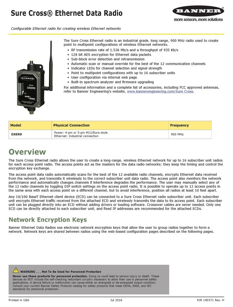
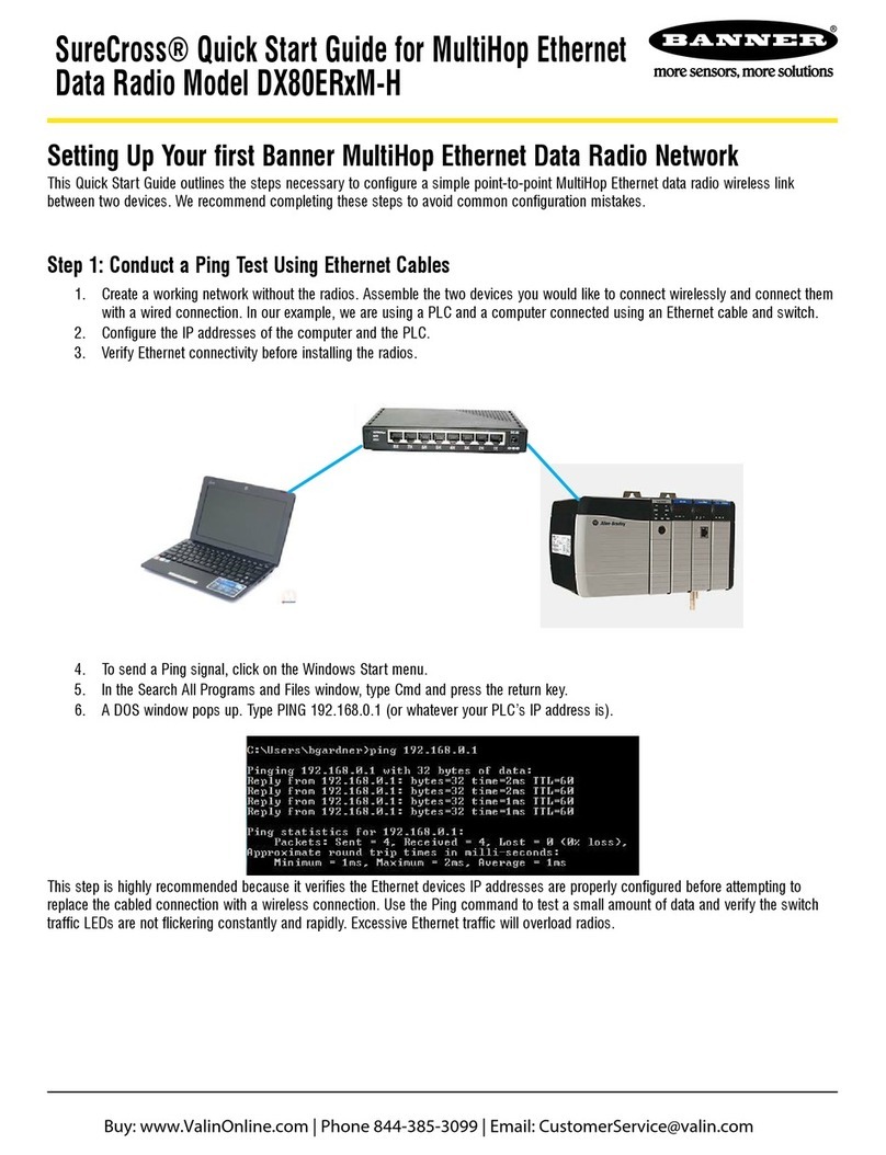
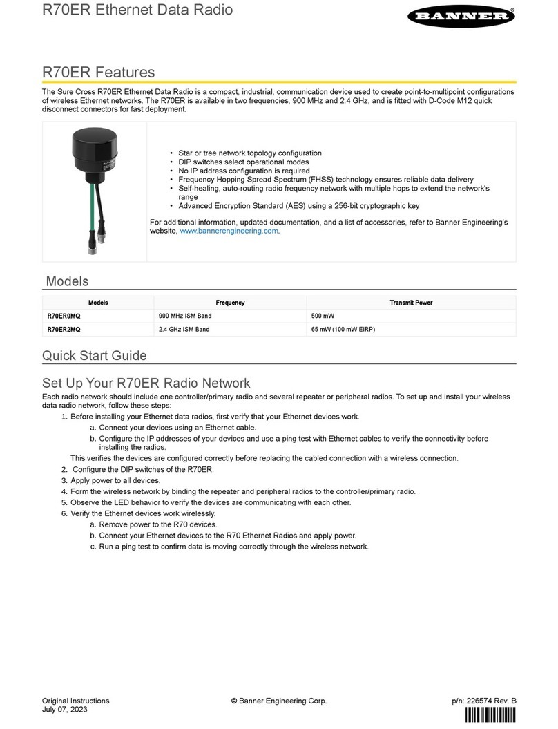
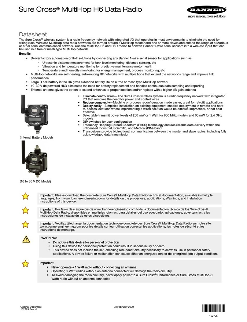
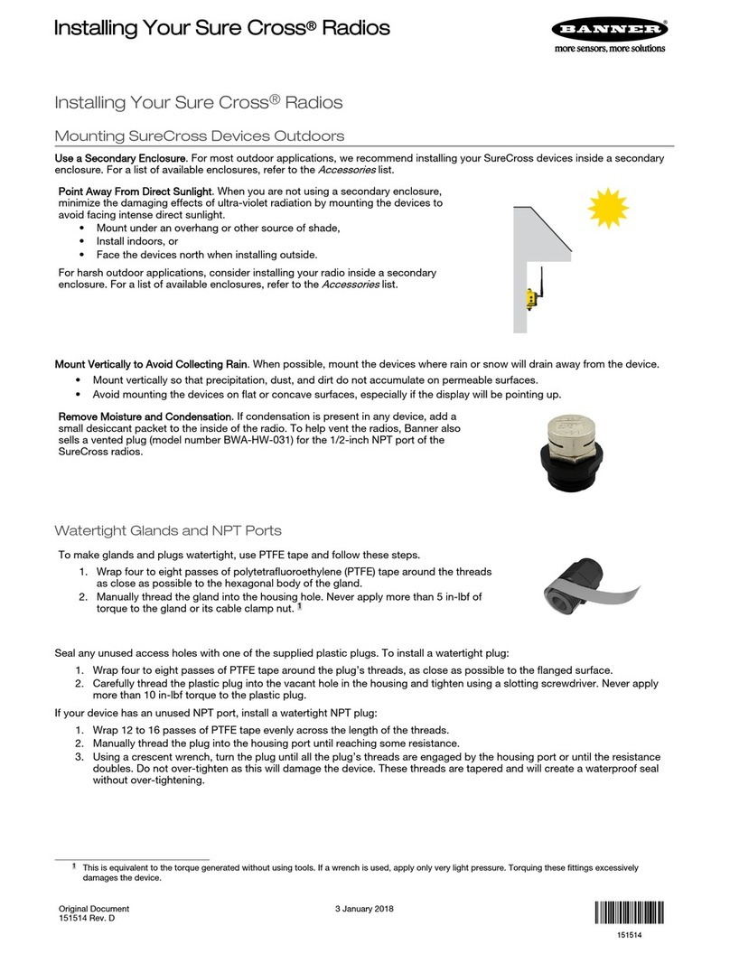
Banner Sure Cross R70SR Series User manual

Original Instructions
June 23, 2023
p/n: 233275 Rev. A
233275
R70SR SNAP SIGNAL™ Serial Data Radio
•
•
•
•
•
R70SR Features
Sure Cross® R70SR Serial Data Radios are compact, industrial, low-power wireless communications devices used to extend the range of
serial communications networks. The Serial Data Radios are available in two frequencies, 900 MHz and 2.4GHz, and are fitted with M12
quick disconnect connectors for fast deployment.
For additional information, updated documentation, and a list of accessories, refer to Banner Engineering's web
site, www.bannerengineering.com.
RS485 serial communication
Star or tree network topology configuration
DIP switches select operational modes
Frequency Hopping Spread Spectrum (FHSS) technology ensures reliable data delivery
Self-healing, auto-routing radio frequency network with multiple hops to extend the network's
range
R70SR Models
Models Frequency Transmit Power
R70SR9MQ 900 MHz ISM Band 1 Watt
R70SR2MQ 2.4 GHz ISM Band 65 mW (100 mW EIRP)
Quick Start Guide
Setting Up Your Data Radio Network
To set up and install your wireless Data Radio network, follow these steps:
Buttons and LEDs
Binding button, LEDs, and DIP switches
Binding button
LEDs
Before installing your data radios, verify that your serial devices work. Connect your serial devices using a serial cable.
1.
Configure the DIP switches of all devices.
2.
Apply power to all devices.
3.
Form the wireless network by binding the repeater and peripheral radios to the controller/primary radio.
4.
Observe the LED behavior to verify the devices are communicating with each other.
5.
Install your wireless sensor network components. For more details about installing your radios, refer to the Sure Cross Installation
Guide (p/n 151514) downloadable from the Wireless Reference Library at www.bannerengineering.com.
6.
© Banner Engineering Corp.
June 23, 2023page 2
(1) For devices powered by batteries integrated into the housing, triple-click button 2, then double-click button 2 to reset the device without removing the battery.
R70SR SNAP SIGNAL™ Serial Data Radio
•
•
•
Configure the DIP Switches
Before changing DIP switch positions, disconnect the power(1). Any changes made to the DIP switches are not recognized until after power is
cycled to the device. For parameters not set using the DIP switches, use the configuration software to make configuration changes. For para
meters set using the DIP switches, the DIP switch positions override any changes made using the configuration software.
Open the Cover
If the cover is in the locked position, the arrow on the cover is above the notch on the base. Follow these steps to unlock and remove the
cover.
Serial Mode vs MultiHop Mode for R70SR Data Radios
As of early 2023, the R70SR Serial Data Radio firmware allows the radio to be configured as either a serial data radio or a MultiHop data ra
dio that is compatible with other Banner Sure Cross MultiHop data radios. These updated R70SR serial data radios also contain an addition
al ID label on the device to assist with MultiHop site surveys. Ignore this label when your radio is operating in serial data radio mode. R70SR
serial data radios manufactured before date code xxxx have different DIP switch configurations. Please refer to datasheet 224673 for the
legacy R70SR model instructions.
Serial Mode--Serial Mode provides the simplest setup and best performance for point-to-point networks and small star networks. Serial mode
is not ideal for medium to large Star or Tree topologies because the client radio broadcasts all messages and does not build a routing table.
This results in slower communication, which is ideal for simple cable replacement applications. There is no need to adjust the Modbus ad
dress of connected devices, resulting in a simpler setup process.
MultiHop Data Radio ModeMultiHop Data Radio mode requires more configuration but allows for much larger Star and Tree topologies be
cause the client radio builds a routing table to more efficiently communicate with each server device on the network. Configuring your data
radio as a MultiHop radio adds the ability to perform a site survey analysis with the MultiHop Configuration Software, offers improved perfor
mance in larger Star and Tree network topologies, and adds the ability to communicate with other Sure Cross MultiHop data radios including
the MutliHop DXM Wireless Controllers.
For additional information, refer to one of the following documents:
MultiHop Data Radio Quick Start Guide (p/n 152653)
MultiHop Data Radio Instruction Manual (p/n 151317)
MultiHop Register Guide (p/n 155289)
DIP Switch Settings for the R70SR in Serial Mode
Device Settings
Dip Switches
1 2 3 4
Serial Mode Off
Serial Routed Mode Off
Serial Broadcast Mode ON
Server Mode OFF OFF
Set this radio to be a client radio. For 900 MHz models, set to 1 W (30dBm) transmit
power; for 2.4 GHz models the transmit power remains at 65 mW OFF ON
Set this radio to be a repeater radio (900 MHz or 2.4 GHz Models) ON OFF
Set this radio to be a server radio. For 900 MHz models, set to 250 mW (24dBm)
transmit power; for 2.4 GHz models the transmit power remains at 65 mW ON ON
Baud Rate and Parity— The baud rate and parity are set to default at 19200; no parity. These settings are not configurable via the DIP
switches and must be changed using AT commands. These settings must match the device wired to the radio's serial port. A faster baud rate
setting may improve system response time. Changing the baud rate does NOT change the radio transmission rate. The software default also
provides the ability to set custom baud rate and timing parameter settings via AT commands. For more information, see the technical
note Changing the Baud Rate and Parity on an R70SR Serial Data Radio (p/n b_51173725).
Serial Routed Mode—Use routed messaging when using a pointtopoint or pointtopointwithrepeater topology. Routing is more robust and
faster than broadcast messaging. In routed mode, the radios will route serial data packets only to a single device. In general, this mode is for
faster communications. If the server radios are in routed mode, they will only route serial data packets to the client radio and will only listen
for serial data packets coming from the client. If the client radio is in routed mode, it will only route serial data packets to the first server radio
that comes into the network. The client radio should only be in routed mode if used in a pointtopoint network.
Rotate the cover counterclockwise so that the notches are aligned together.
1.
Pull the top cover off.
2.
© Banner Engineering Corp.

R70SR SNAP SIGNAL™ Serial Data Radio
June 23, 2023 page 3
Serial Broadcast Mode—Broadcast mode allows for more flexible radio layouts and is used in the star and MultiHop tree topologies. These
topologies are much more flexible but they are slower. When using broadcast mode, a small percentage of data packets will not be reach
their destination. Broadcast mode requires the application layer to automatically retry packets that time out. In networks with multiple server,
the client radio must use broadcast mode, but the server radios can be set to use routing mode to route their data packets back to the client
radio. In broadcast mode, the radios route serial data packets to all devices in the network. In general, this mode will have slower communi
cation speeds but will allow for much more system flexibility. If the servers and repeaters are in broadcast mode, they route serial data pack
ets to all other devices and listen to serial data packets coming from all devices. If the client radio is in broadcast mode, it routes serial data
packets to all servers and repeaters and listens to serial data packets coming from all devices.
Transmit Power Levels—The 900 MHz radios transmit at 1 Watt (30 dBm) or 250 mW (24 dBm). The 250 mW mode reduces the radio's
range, which can help avoid cross talk in areas with multiple systems. For 2.4 GHz models, this DIP switch is disabled. The transmit power
for 2.4 GHz is fixed at about 65 mW EIRP (18 dBm).
Network Topologies in Serial Mode
Cable Replacement Configuration for Point-to-Point Networks--In this simple cable replacement application, the radio system knows all data
originating at one end must be transmitted to the other end. This allows the radio system to automatically correct for transmission problems
and it also provides the greatest throughput. This is the fastest configuration.
Simple point-to-point network
Client radio Server radio
Device Settings
DIP Switches
1 2 3 4
Client configuration route to a server Off Off Off On
Server configuration route to the client Off Off Off Off
Cable Replacement with a RepeaterIn this simple cable replacement application with a repeater, the radio system still knows all data origi
nating at one end must be transmitted to the other end. In this application, there are no serial devices connected to the repeater(s). The sys
tem still corrects for transmission problems, but it takes time to repeat the message. The network delay is double that of a system with no re
peater.
Point-to-point network with repeater
Client radio Server radioRepeater radio
Device Settings
DIP Switches
1 2 3 4
Client configuration route to a server Off Off Off On
Repeater configuration Off On On Off
Server configuration route to the client Off Off Off Off
Serial Broadcast Mode Configuration with a Star Network--In this more complex star topology, the client radio at the center of the network
can communicate to many server radios. A common example would be a PLC at the center communicating with many remote I/O systems.
The star topology is slower than a point-to-point network, but faster than a tree network.
© Banner Engineering Corp.
June 23, 2023page 4
R70SR SNAP SIGNAL™ Serial Data Radio
Serial broadcast mode configuration with a star network
Client Server
Server
Server
Server
ServerServer
Device Settings
DIP Switches
1 2 3 4
Client configuration to broadcast to all devices Off On Off On
Server configuration to route to the client Off Off Off Off
Serial Broadcast Mode Configuration with a Tree Network--A tree network using multiple radios is very flexible; many repeaters and servers
can be combined to cover vast areas and get around hills or buildings. In the other networks, the wireless "hops" are minimized. In this sys
tem, you can "hop" as much as you need to, but the tradeoff is speed. This is the slowest of the network layouts. For larger tree networks,
we recommend avoiding serial broadcast mode and switching the radios to MultiHop Data Radio mode.
Serial broadcast mode configuration with a tree network
Client
ServerServer
RepeaterServer
Device Settings
DIP Switches
1 2 3 4
Client configuration to broadcast to all devices Off On Off On
Repeater configuration to broadcast to all devices Off On On Off
Server configuration to broadcast to all devices Off On Off Off
IMPORTANT: Star and tree topologies in serial mode use a Broadcast radio technique. Broadcasting allows for many
radios and larger, complex systems but also introduces a small chance that a data packet can be lost. These network
topologies require the control system to automatically resend missing data packets. Most control protocols (like Mod
bus) will work fine. Other serial stream-based protocols may not be as tolerant and should only be used with point-to-
point topologies.
© Banner Engineering Corp.
R70SR SNAP SIGNAL™ Serial Data Radio
June 23, 2023 page 5
DIP Switch Settings for the R70SR in MultiHop Mode
Device Settings
DIP Switches
1234
MultiHop Data Radio Mode ON
Power/Radio Selection 900 MHz models are set to 1 W (30dBm) transmit power; 2.4 GHz
models are set to GFSK Radio modulation (transmit power remains at 65 mW) OFF
Power/Radio Selection - 900 MHz models are set to 250 mW (24dBm) transmit power; 2.4
GHz models are set to FLRC Radio modulation (transmit power remains at 65 mW) ON
Set this radio to be a MultiHop server radio OFF OFF
Set this radio to be a MultiHop client radio OFF ON
Set this radio to be a MultiHop repeater radio ON OFF
Reserved ON ON
Network Topologies in MultiHop Mode
Cable Replacement Configuration for Point-to-Point Networks--In this simple cable replacement application, the radio system knows all data
originating at one end must be transmitted to the other end. This allows the radio system to automatically correct for transmission problems
and it also provides the greatest throughput. This is the fastest configuration.
Simple cable replacement configuration for a point-to-point network
Client radio Server radio
Device Settings
DIP Switches
1 2 3 4
Client configuration On Off Off On
Server configuration On Off Off Off
Cable Replacement Configuration for with Repeaters--In this simple cable replacement application with a repeater radio, the radio system
still knows all data originating at one end must be transmitted to the other end. In this application, no serial devices are connected to the
repeater(s). The system still corrects for transmission problems, but it takes time to repeat the message. The network delay is double that of
a system with no repeater.
Simple cable replacement configuration for a point-to-point network with a repeater
Client radio Server radioRepeater radio
Device Settings
DIP Switches
1 2 3 4
Client configuration On Off Off On
Repeater configuration On Off On Off
Server configuration On Off Off Off
MultiHop Mode (Star Network)--In this more complex star topology, the client radio at the center of the network can communicate with many
server radios. A common example would be a PLC at the center communicating with many remote I/O systems. The star topology is slower
than a point-to-point network but faster than a tree network.
© Banner Engineering Corp.

June 23, 2023page 6
R70SR SNAP SIGNAL™ Serial Data Radio
MultiHop mode star network
Client Server
Server
Server
Server
ServerServer
Device Settings
DIP Switches
1 2 3 4
Client configuration On Off Off On
Server configuration On Off Off Off
MultiHop Mode with a Tree Network Configuration—A tree network using MultiHop radios is the most powerful wireless system possible;
many repeaters and server can be combined to cover vast areas and get around hills or buildings. In the other networks, the wireless "hops"
are minimized. In this system, you can "hop" as much as you need to. In MultiHop mode, there may be some speed tradeoffs, but it is still
significantly faster and more reliable than a Tree Topology in Serial Mode.
MultiHop mode with a tree network
Client
ServerServer
RepeaterServer
Device Settings
DIP Switches
1 2 3 4
Client configuration On Off Off On
Repeater configuration On Off On Off
Server configuration On Off Off Off
Packet Routing in MultiHop Data Radio Mode—In MultiHop Data Radio mode, the client radio first discovers all connected Modbus server in
the network, then uses the Modbus ID contained in the incoming Modbus message to wirelessly route the packet only to the radio attached
to the target Modbus server. The packet is then passed via the radio’s serial interface to the Modbus device where it is processed. This is en
tirely transparent to the user. Direct packet-by-packet routing offers an advantage over broadcast addressing with MultiHop paths because
each hop in the path can be retried independently in the event of a packet error. This results in significantly more reliable packet delivery over
MultiHop paths. Modbus IDs 01 through 10 are reserved for server directly connected to the host (local I/O). As such, polling messages ad
dressed to these devices are not relayed over the wireless link. Use Modbus IDs 11 through 60 for remote Modbus server — devices serially
connected to an R70 Server or Repeater — allowing a maximum of 50 attached devices.
© Banner Engineering Corp.

R70SR SNAP SIGNAL™ Serial Data Radio
June 23, 2023 page 7
Apply Power
The R70SR Serial Data Radio is fitted with a 5pin M12 connector for fast installations. Use straight splitter cordsets to connect multiple de
vices and power to the R70SR Serial Radio. For a list of splitter and cordset options, see "Accessories for the R70SR Data Radio " on page
10.
5pin M12 Male Connector Pin Wire Color Wiring Description
1
4
5
3
2
1 Brown (bn) 10 to 30 V DC
2 White (wh) RS485 / D1 / B / +
3 Blue (bu) DC common (GND)
4 Black (bk) RS485 / D0 / A /
5 Gray (gy) No connection
Bind the R70SR Serial Data Radio to Form a Network
To create your network, bind the R70SR to the designated server radio.
Verify your radio DIP Switches and connected device Modbus IDs are set according to "Configure the DIP Switches" on page 2.
Binding the serial data radios ensures all radios within a network communicate only with the other radios within the same network. The serial
data primary radio automatically generates a unique binding code when it enters binding mode. This code is transmitted to all radios within
range that are also in binding mode. After a repeater/server is bound, the repeater/server radio accepts data only from the client radio to
which it is bound. The binding code defines the network, and all radios within a network must use the same binding code.
Child (Server) Radios Synchronize to the Parent (Client) Radios
The synchronization process enables a Sure Cross radio to join a wireless network formed by a client radio. A simple point-to-point network
with one client radio and one server radio synchronizes quickly after power up; larger MultiHop networks may take a few minutes to synchro
nize. First, all radios within range of the client data radio wirelessly synchronize to the client radio. These radios may be server or repeater
radios.
After repeater radios are synchronized to the client radio, any radios that are not in sync with the client but can "hear" the repeater radio will
synchronize to the repeater radios. Each repeater “family” that forms a wireless network path creates another layer of synchronization
process. When testing the devices before installation, verify the radios are at least two meters apart or the communications may fail.
MultiHop Configuration Software
Use Banner’s MultiHop Configuration Software to view your MultiHop radio network and configure the radio and its I/O.
Apply power to all radios and place the R70SR radio at least two meters away from the client radio.
1.
Remove the cover. See "Open the Cover" on page 2.
2.
On the client radio: Tripleclick the binding button to put the client radio into binding mode.
Both LEDs flash red.
3.
On the R70SR: Tripleclick the binding button to put the R70SR into binding mode.
The radio enters binding mode and searches for any client radio in binding mode. While searching for the client radio, the two red
LEDs flash alternately. When the radio finds the client radio and is bound, both red LEDs are solid for four seconds, then both red
LEDs flash simultaneously four times.
4.
Reinstall the R70SR's cover.
5.
Repeat steps 3 through 5 for as many radios as are needed for your network.
6.
On the client radio: After all radios are bound, doubleclick the binding button to exit binding mode on the client.
The network begins to form after the client data radio exits binding mode.
7.
On the client radio: Reinstall the cover to protect the button and radio board.
8.
© Banner Engineering Corp.

June 23, 2023page 8
R70SR SNAP SIGNAL™ Serial Data Radio
•
•
•
•
MultiHop Configuration Software Network and Device Overview screen
The software connects to a MultiHop client radio using one of four methods.
Serial; using a USB to RS485 (for RS485 radios) or a USB to RS232 (for RS232 radios) converter cable.
Modbus TCP; using an Ethernet connection to an Ethernet radio client.
Serial DXM; using a USB cable to a DXM Controller to access a MultiHop client radio.
TCP DXM: using an Ethernet connection to a DXM Controller to access a MultiHop client radio.
Banner recommends using BWA-UCT-900, an RS-485 to USB adapter cable with a wall plug that can power your radio while you configure
it. The adapter cable is not required when connecting to a DXM Controller.
Download the most recent software revision from the Wireless Reference Library on Banner Engineering's web
site: www.bannerengineering.com.
Client Radio LED Behavior
All bound radios set to operate as client radios follow this LED behavior after powering up.
Process Steps Response LED 1 LED 2
1 Apply power to the client radio Solid amber
2 The client radio enters RUN mode. Flashes green
Data packets begin transmitting between the client and its children radios. Flashes amber
In binding mode Flashes red Flashes red
Server Radio LED Behavior
All bound radios set to server or repeater modes follow this LED behavior after powering up.
Process Steps Response LED 1 LED 2
1 Apply power to the radio Solid amber (briefly)
2 The server/repeater searches for a parent device. Flashes red
3 A parent device is detected. The client/repeater searches for other parent radios within
range. Solid red
4 The server/repeater selects a suitable parent. Solid amber
5 The server/repeater attempts to synchronize to the selected parent. Solid red
6 The server/repeater is synchronized to the parent. Flashes green
7 The server/repeater enters RUN mode. Solid green, then flashes
green
Data packets begin transmitting between the server/repeater and its parent radio. Flashes amber
In binding mode Flashes red Flashes red
Installing Your Sure Cross® Radios
Please refer to one of these instruction manuals to install your wireless network components.
© Banner Engineering Corp.

R70SR SNAP SIGNAL™ Serial Data Radio
June 23, 2023 page 9
•
•
DX80 Performance Wireless I/O Network Instruction Manual: 132607
MultiHop Data Radio Instruction Manual: 151317
Specifications for the R70xR Models
Radio Range
900 MHz, 500 mW: Up to 1.6 km (1 mile) (internal antenna)
2.4 GHz, 65 mW: Up to 1000 m (3280 ft) with line of sight (in
ternal antenna)
Antenna Minimum Separation Distance
900 MHz, 500 mW: 4.57 m (15 ft)
2.4 GHz, 65 mW: 0.3 m (1 ft)
Radio Transmit Power
900 MHz, 500 mW: 27 dBm
2.4 GHz, 65 mW: 18 dBm (65 mW) conducted, less than or
equal to 20 dBm (100 mW) EIRP
Spread Spectrum Technology
FHSS (Frequency Hopping Spread Spectrum)
Communication Protocols
Modbus® RTU, Modbus/TCP, EtherNet/IP™
EtherNet/IP™ is a trademark of ODVA, Inc.Modbus® is a reg
istered trademark of Schneider Electric USA, Inc.
Security Protocols
TLS, SSL, HTTPS
900 MHz Compliance
Radio module is indicated by the product label marking
Contains FCC ID: UE3RM7023: FCC Part 15, Subpart C,
15.247
Contains IC: 7044ARM7023
2.4 GHz Compliance (SX243 Radio Module)
Radio module is indicated by the product label marking
Contains FCC ID: UE3SX243: FCC Part 15, Subpart C,
15.247
Radio Equipment Directive (RED) 2014/53/EU
ETSI/EN: EN 300 328 V2.2.2 (2019-07) [RED HarmStds]
Contains IC: 7044A-SX243
ANATEL: 037372204042
Radio Data Transfer Rate
900 MHz: 300 kbps
2.4 GHz: 250 kbps
Supply Voltage
10 V DC to 30 V DC (Outside the USA: 12 V DC to 24 V DC,
± 10%)
For European applications, power this device from a Limited
Power Source as defined in EN 609501.
Average Current for 900 MHz Radios (1500 byte packets at 50 ms
intervals)
Client Mode: 0.12 A at 12 V; 0.06 A at 24 V
Server Mode: 0.03 A at 12 V; 0.017 A at 24 V
Average Current for 2.4 GHz Radios (1500 byte packets at 50 ms
intervals
Client Mode: 0.035 A at 12 V; 0.02 A at 24 V
Server Mode: 0.022 A at 12 V; 0.014 A at 24 V
Interface
Two bi-color LED indicators
One button (under the small round cover)
Construction
Base: Black polycarbonate
Cover: Translucent gray polycarbonate
Operating Conditions
–40 °C to +85 °C (–40 °F to +185 °F)
95% maximum relative humidity (non-condensing)
Radiated Immunity: 10 V/m (EN 61000-4-3)
Operating the devices at the maximum operating conditions
for extended periods can shorten the life of the device.
Environmental Ratings
IP65
For installation and waterproofing instructions, go
to www.bannerengineering.com and search for the complete
instruction manual
Shock and Vibration
All models meet IEC 60068-2-6 and IEC 60068-2-27 testing
criteria
Shock: 30G 11 ms duration, half sine wave per IEC
60068-2-27
Vibration: 10 Hz to 55 Hz, 0.5 mm peak-to-peak amplitude per
IEC 60068-2-6
Certifications
Banner Engineering BV
Park Lane, Culliganlaan 2F bus 3
1831 Diegem, BELGIUM
(CE/UKCA approval only applies to 2.4 GHz models)
Dimensions for the R70SR
All measurements are listed in millimeters, unless noted otherwise.
© Banner Engineering Corp.

June 23, 2023page 10
R70SR SNAP SIGNAL™ Serial Data Radio
Dimensions for the R70SR
M30 x 1
M12 x 1
Accessories for the R70SR Data Radio
4Pin Threaded M12 Cordsets—Single Ended
Model Length Style Dimensions Pinout (Female)
MQDC-403 1 m (3.28 ft)
Straight
44 Typ.
ø 14.5
M12 x 1
2
3
4
1
5
1 = Brown
2 = White
3 = Blue
4 = Black
5 = Not used
MQDC-406 2 m (6.56 ft)
MQDC-410 3 m (9.8 ft)
MQDC-415 5 m (16.4 ft)
MQDC-430 9 m (29.5 ft)
MQDC-450 15 m (49.2 ft)
4Pin Threaded M12 Cordsets—Single Ended
Model Length Style Dimensions Pinout (Female)
MQDC-406RA 2 m (6.56 ft)
RightAngle
32 Typ.
[1.26"]
30 Typ.
[1.18"]
ø 14.5 [0.57"]
M12 x 1
1
23
4
1 = Brown
2 = White
3 = Blue
4 = Black
5 = Not used
MQDC-415RA 5 m (16.4 ft)
MQDC-430RA 9 m (29.5 ft)
MQDC-450RA 15 m (49.2 ft)
© Banner Engineering Corp.

R70SR SNAP SIGNAL™ Serial Data Radio
June 23, 2023 page 11
4Pin Threaded M12 Cordsets—Double Ended
Model Length Style Dimensions Pinout
MQDEC401SS 0.31 m (1 ft)
Male Straight/Female
Straight
40 Typ.
[1.58"]
ø 14.5 [0.57"]
M12 x 1
44 Typ.
[1.73"]
ø 14.5 [0.57"]
M12 x 1
Female
2
3
4
1
Male
1
4
3
2
1 = Brown
2 = White
3 = Blue
4 = Black
MQDEC-403SS 0.91 m (2.99 ft)
MQDEC-406SS 1.83 m (6 ft)
MQDEC412SS 3.66 m (12 ft)
MQDEC420SS 6.10 m (20 ft)
MQDEC430SS 9.14 m (30.2 ft)
MQDEC450SS 15.2 m (49.9 ft)
MQDEC-403RS 0.91 m (2.99 ft)
Male RightAngle/
Female Straight
[1.73"]
ø 14.5 [0.57"]
M12 x 1
[1.26"]
[1.18"]
ø 14.5 [0.57"]
M12 x 1
MQDEC-406RS 1.83 m (6 ft)
MQDEC-412RS 3.66 m (12 ft)
MQDEC420RS 6.10 m (20 ft)
MQDEC-430RS 9.14 m (30.2 ft)
MQDEC-450RS 15.2 m (49.9 ft)
MQDEC-403RR 0.9 m (2.9 ft)
Male RightAngle/Fe
male RightAngle
[1.26"]
[1.18"]
ø 14.5 [0.57"]
M12 x 1
MQDEC-406RR 1.8 m (5.9 ft)
MQDEC-412RR 3.6 m (11.8 ft)
MQDEC-420RR 6.1 m (20 ft)
5Pin Threaded M12 Splitter Cordset with Flat Junction—Double Ended
Model Trunk (Male) Branches (Female) Pinout (Male) Pinout (Female)
CSB4-M1251M1250 0.3 m (0.98 ft) Four (no cable)
1
4
5
3
2
2
3
4
1
5
Branch 1
Branch 2
Branch 3
Branch 4
3 x 18
72 mm
2 x 19
32 mm
1 = Brown
2 = White
3 = Blue
4 = Black
5 = Gray
© Banner Engineering Corp.

June 23, 2023page 12
R70SR SNAP SIGNAL™ Serial Data Radio
•
•
•
•
•
•
•
•
•
•
•
•
•
5Pin Threaded M12 Splitter Tee
Model Description Pinout (Male) Pinout (Female)
CSB-M1250M1250-T Female trunk, 1 female branch, 1 male
branch
1
4
5
3
2
1 = Brown
2 = White
3 = Blue
2
3
4
1
5
4 = Black
5 = Green/Yellow
LMB30LP
Low profile
30 mm mounting hole
300 series stainless steel
2 X Ø5.5
Ø30.5
65
50
40
26
WC-R70 Washdown Cover
FDAgrade silicone
Fits R70 data radios
IP67 and IP69K rated
PSW-24-1
24 V DC, 1 A Class 2 UL Listed power supply
100 V AC to 240 V AC 50/60 Hz input
2 m (6.5 ft) PVC cable with M12 quick disconnect
Includes Type A (US, Canada, Japan, Puerto Rico, Taiwan), Type C (Germany, France, South Korea, Netherlands,
Poland, Spain, Turkey), Type G (United Kingdom, Ireland, Singapore, Vietnam), and Type I (China, Australia, New
Zealand) AC detachable input plugs
TYPE A TYPE G
TYPE C TYPE I
Warnings
WARNING:
Do not use this device for personnel protection
Using this device for personnel protection could result in serious injury or death.
This device does not include the selfchecking redundant circuitry necessary to allow its use in personnel safe
ty applications. A device failure or malfunction can cause either an energized (on) or de-energized (off) output
condition.
IMPORTANT: Please download the complete R70SR Snap Signal Serial Data Radio technical documentation, available
in multiple languages, from www.bannerengineering.com for details on the proper use, applications, Warnings, and in
stallation instructions of this device.
IMPORTANT: Por favor descargue desde www.bannerengineering.com toda la documentación técnica de los R70SR
Snap Signal Serial Data Radio, disponibles en múltiples idiomas, para detalles del uso adecuado, aplicaciones, adver
tencias, y las instrucciones de instalación de estos dispositivos.
IMPORTANT: Veuillez télécharger la documentation technique complète des R70SR Snap Signal Serial Data Radio sur
notre site www.bannerengineering.com pour les détails sur leur utilisation correcte, les applications, les notes de sécu
rité et les instructions de montage.
Install and properly ground a qualified surge suppressor when installing a remote antenna system. Remote antenna configurations installed
without surge suppressors invalidate the manufacturer's warranty. Keep the ground wire as short as possible and make all ground connec
tions to a single-point ground system to ensure no ground loops are created. No surge suppressor can absorb all lightning strikes; do not
touch the Sure Cross® device or any equipment connected to the Sure Cross device during a thunderstorm.
© Banner Engineering Corp.

R70SR SNAP SIGNAL™ Serial Data Radio
June 23, 2023 page 13
•
•
•
•
•
•
Exporting Sure Cross® Radios. It is our intent to fully comply with all national and regional regulations regarding radio frequency emis
sions. Customers who want to re-export this product to a country other than that to which it was sold must ensure the device is approved in
the destination country. The Sure Cross wireless products were certified for use in these countries using the antenna that ships with the prod
uct. When using other antennas, verify you are not exceeding the transmit power levels allowed by local governing agencies. This device has
been designed to operate with the antennas listed on Banner Engineering’s website and having a maximum gain of 9 dBm. Antennas not in
cluded in this list or having a gain greater than 9 dBm are strictly prohibited for use with this device. The required antenna impedance is 50
ohms. To reduce potential radio interference to other users, the antenna type and its gain should be so chosen such that the equivalent
isotropically radiated power (EIRP) is not more than that permitted for successful communication. Consult with Banner Engineering Corp. if
the destination country is not on this list.
IMPORTANT:
Never operate a 1 Watt radio without connecting an antenna
Operating 1 Watt radios without an antenna connected will damage the radio circuitry.
To avoid damaging the radio circuitry, never apply power to a Sure Cross® Performance or Sure Cross Multi
Hop (1 Watt) radio without an antenna connected.
IMPORTANT:
Electrostatic discharge (ESD) sensitive device
ESD can damage the device. Damage from inappropriate handling is not covered by warranty.
Use proper handling procedures to prevent ESD damage. Proper handling procedures include leaving devices
in their anti-static packaging until ready for use; wearing anti-static wrist straps; and assembling units on a
grounded, static-dissipative surface.
Banner Engineering Corp Limited Warranty
Banner Engineering Corp. warrants its products to be free from defects in material and workmanship for one year following the date of ship
ment. Banner Engineering Corp. will repair or replace, free of charge, any product of its manufacture which, at the time it is returned to the
factory, is found to have been defective during the warranty period. This warranty does not cover damage or liability for misuse, abuse, or the
improper application or installation of the Banner product.
THIS LIMITED WARRANTY IS EXCLUSIVE AND IN LIEU OF ALL OTHER WARRANTIES WHETHER EXPRESS OR IMPLIED (INCLUD
ING, WITHOUT LIMITATION, ANY WARRANTY OF MERCHANTABILITY OR FITNESS FOR A PARTICULAR PURPOSE), AND WHETHER
ARISING UNDER COURSE OF PERFORMANCE, COURSE OF DEALING OR TRADE USAGE.
This Warranty is exclusive and limited to repair or, at the discretion of Banner Engineering Corp., replacement. IN NO EVENT SHALL BAN
NER ENGINEERING CORP. BE LIABLE TO BUYER OR ANY OTHER PERSON OR ENTITY FOR ANY EXTRA COSTS, EXPENSES,
LOSSES, LOSS OF PROFITS, OR ANY INCIDENTAL, CONSEQUENTIAL OR SPECIAL DAMAGES RESULTING FROM ANY PRODUCT
DEFECT OR FROM THE USE OR INABILITY TO USE THE PRODUCT, WHETHER ARISING IN CONTRACT OR WARRANTY, STATUTE,
TORT, STRICT LIABILITY, NEGLIGENCE, OR OTHERWISE.
Banner Engineering Corp. reserves the right to change, modify or improve the design of the product without assuming any obligations or lia
bilities relating to any product previously manufactured by Banner Engineering Corp. Any misuse, abuse, or improper application or installa
tion of this product or use of the product for personal protection applications when the product is identified as not intended for such purposes
will void the product warranty. Any modifications to this product without prior express approval by Banner Engineering Corp will void the prod
uct warranties. All specifications published in this document are subject to change; Banner reserves the right to modify product specifications
or update documentation at any time. Specifications and product information in English supersede that which is provided in any other lan
guage. For the most recent version of any documentation, refer to: www.bannerengineering.com.
For patent information, see www.bannerengineering.com/patents.
FCC Part 15 Class A
This equipment has been tested and found to comply with the limits for a Class A digital device, pursuant to part 15 of the FCC Rules. These
limits are designed to provide reasonable protection against harmful interference when the equipment is operated in a commercial environ
ment. This equipment generates, uses, and can radiate radio frequency energy and, if not installed and used in accordance with the instruc
tion manual, may cause harmful interference to radio communications. Operation of this equipment in a residential area is likely to cause
harmful interference in which case the user will be required to correct the interference at his own expense.
Industry Canada Statement for Intentional Radiators
This device contains licenceexempt transmitters(s)/receiver(s) that comply with Innovation, Science and Economic Development Canada’s
licence-exempt RSS(s). Operation is subject to the following two conditions:
Cet appareil contient des émetteurs/récepteurs exemptés de licence conformes à la norme Innovation, Sciences, et Développement
économique Canada. L’exploitation est autorisée aux deux conditions suivantes:
This device may not cause interference.
1.
This device must accept any interference, including interference that may cause undesired operation of the device.
2.
L’appareil ne doit pas produire de brouillage.
1.
© Banner Engineering Corp.

June 23, 2023page 14
R70SR SNAP SIGNAL™ Serial Data Radio
Document title: R70SR SNAP SIGNAL™ Serial Data Radio
Part number: 233275
Revision: A
Original Instructions
© Banner Engineering Corp. All rights reserved.
233275
L’utilisateur de l’appareil doit accepter tout brouillage radioélectrique subi, même si le brouillage est susceptible d’en compromettre
le fonctionnement.
2.
© Banner Engineering Corp.
Other manuals for Sure Cross R70SR Series
1
This manual suits for next models
2
Table of contents
Other Banner Radio manuals

Banner
Banner SureCross DX80DR9M-H1 User manual

Banner
Banner SureCross DX80SRxM-H User manual

Banner
Banner Sure Cross MultiHop H6 User manual

Banner
Banner SureCross DX80ER M-H Series User manual

Banner
Banner SureCross DX80DR2M-H User manual

Banner
Banner Sure Cross R70SR Series User manual

Banner
Banner SureCross Quick start guide

Banner
Banner Sure Cross DX80 User manual

Banner
Banner R70ER User manual

Banner
Banner Sure Cross MultiHop User manual