Building Automation Products, Inc., 750 North Royal Avenue, Gays Mills, WI 54631 USA
T
el:+1-608-735-4800 • Fax+1-608-735-4804 • E-mail:
[email protected] • Web:www
.bapihvac.com
Specications subject to change without notice.
1 of 4
Installation & Operating Instructions
rev. 08/21/1728173_ins_CO2_Duct
CO2 Duct and Rough Service Sensor
The BAPI CO2 Duct Sensor is an accurate and reliable way
of incorporating demand controlled ventilation. It measures
CO2 in ranges of 0 to 2,000, 0 to 5,000, 0 to 10,000 and 0
to 50,000 ppm with a eld selectable output of 0 to 5 or 0 to
10 VDC.
The Single Beam (ACD) unit has been optimized for
periodically unoccupied areas and features automatic
background calibration over a long time period to reduce
drift. The Dual Channel (DCD) “24/7” unit has been
optimized for continuously occupied areas and features a
3-point calibration process.
Barometric pressure changes from altitude or weather
can affect CO2 sensors, even putting them outside of their
specied accuracy. The BAPI unit has a built-in Barometric
pressure sensor that continuously compensates the output
for accurate readings despite the weather or altitude.
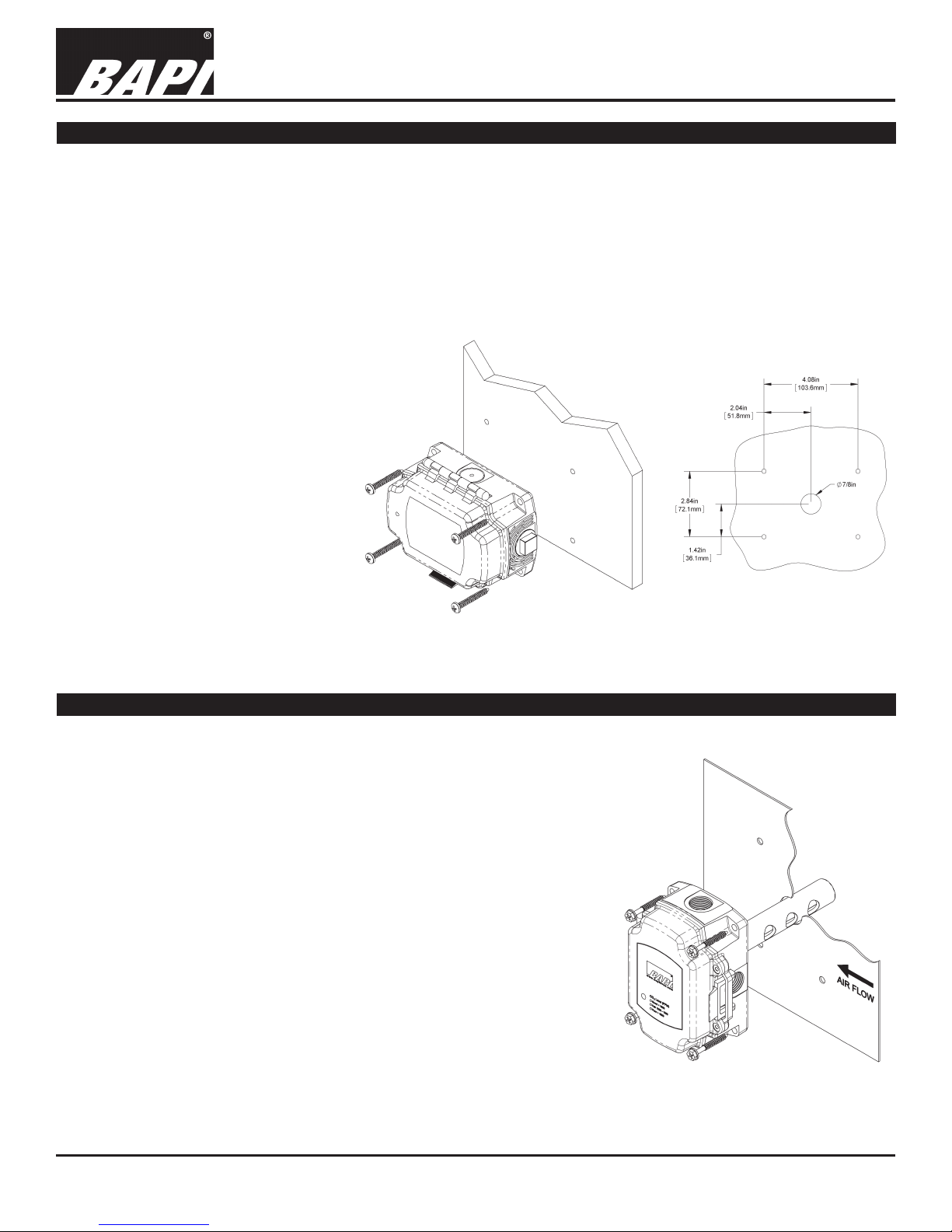
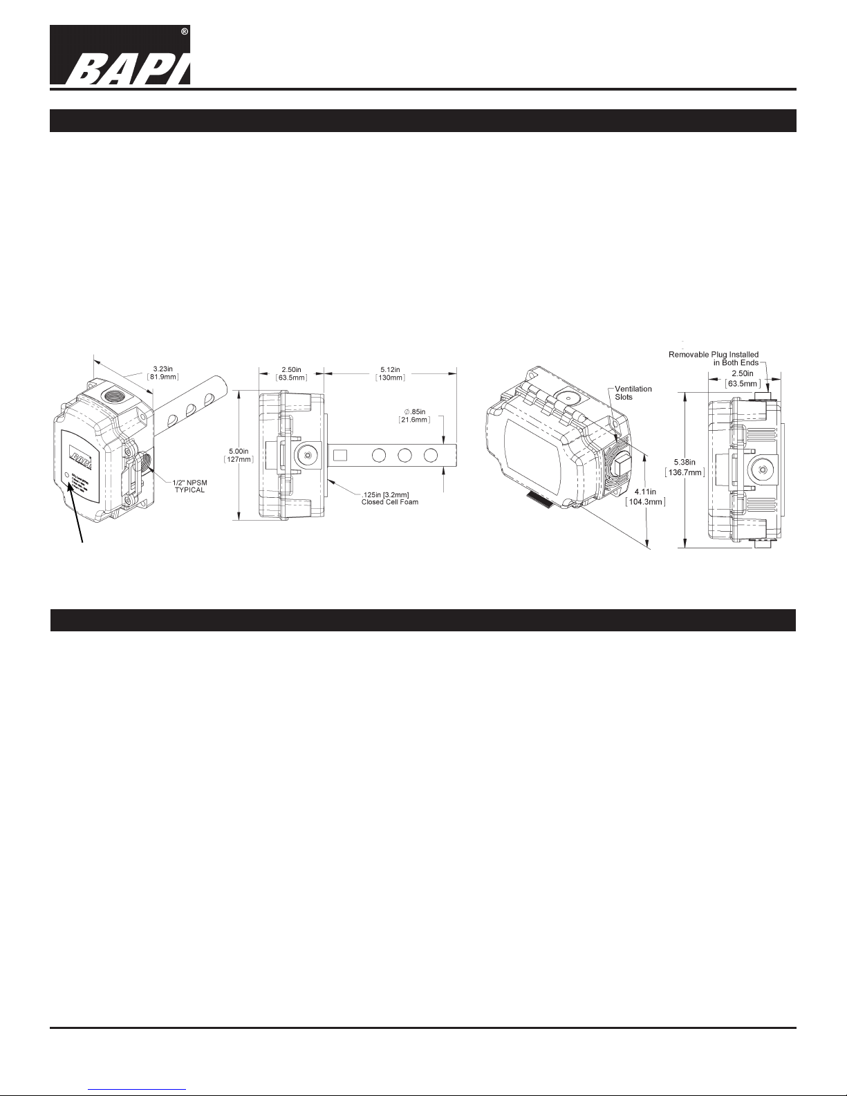
The Duct unit samples duct air using an aspiration tube.
The Rough Service unit features a ventilated BAPI-Box and
is ideal for areas such as outdoor air plenums, equipment
rooms, attics, green houses and warehouses. Optional
indication of the CO2 level as “Good, Fair or Poor” is
available as a 3-color LED for 0 to 2,000 ppm range units.
Identication and Overview
Fig. 1: Duct CO2 Sensor
Three-color
LED Fig. 2: Rough Service CO2 Sensor
Specications
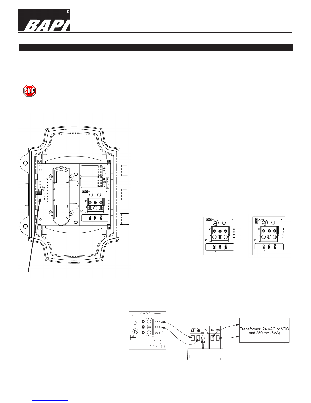
Power:
12 to 24 VDC, 240mA
18 to 24 VAC, 12 VA Peak
CO2 Sensing Elements:
Single Beam Non-Dispersive Infrared (NDIR)
or Dual Channel NDIR for “24/7” Model
Selectable Output:
0 to 5 VDC or 0 to 10 VDC
Termination: 3 Terminals, 16 to 22 AWG
Wiring: 2 Pair
Operating Environment:
32 to 122°F (0 to 50°C)
0 to 95%RH non-condensing
Enclosure Material:
Polycarbonate, UL94 V-O
CO2 Detection Range:
0 to 2,000, 0 to 5,000, 0 to 10,000 and 0 to 50,000 ppm
Start-Up Time: 10 Minutes
Response Time:
Less Than 5 Minutes (after Start-Up Time)
CO2 Accuracy:
(Automatic Background Calib. Single Channel Model)
400 to 1,250 ppm: ±30ppm or 3% of reading,
whichever is greater
1,250 to 2,000 ppm: ±5% of reading + 30ppm
CO2 Accuracy:
(“24/7” Dual Channel Model)
75ppm or 10% of reading (whichever is greater)
CO2 Drift Stability (DCD “24/7” Units):
<5% of full scale over life of product.
Optional 3-Color LED (0 to 2,000 ppm range only):
Good, Green < 1,000 PPM CO2
Fair, Orange = 1,000 to 1,500 PPM CO2
Poor, Red > 1,500 PPM CO2
Certications: RoHS
Warranty Period:
5 Years from manufacture date