BAPI CO2 User manual

Installation and Operating Instructions
CO2 Room Sensor in the BAPI-Stat 3 Enclosure
with Common Ground Conguration
Specications subject to change without notice.
26141_ins_room_CO2
1 of 6
rev. 04/27/18
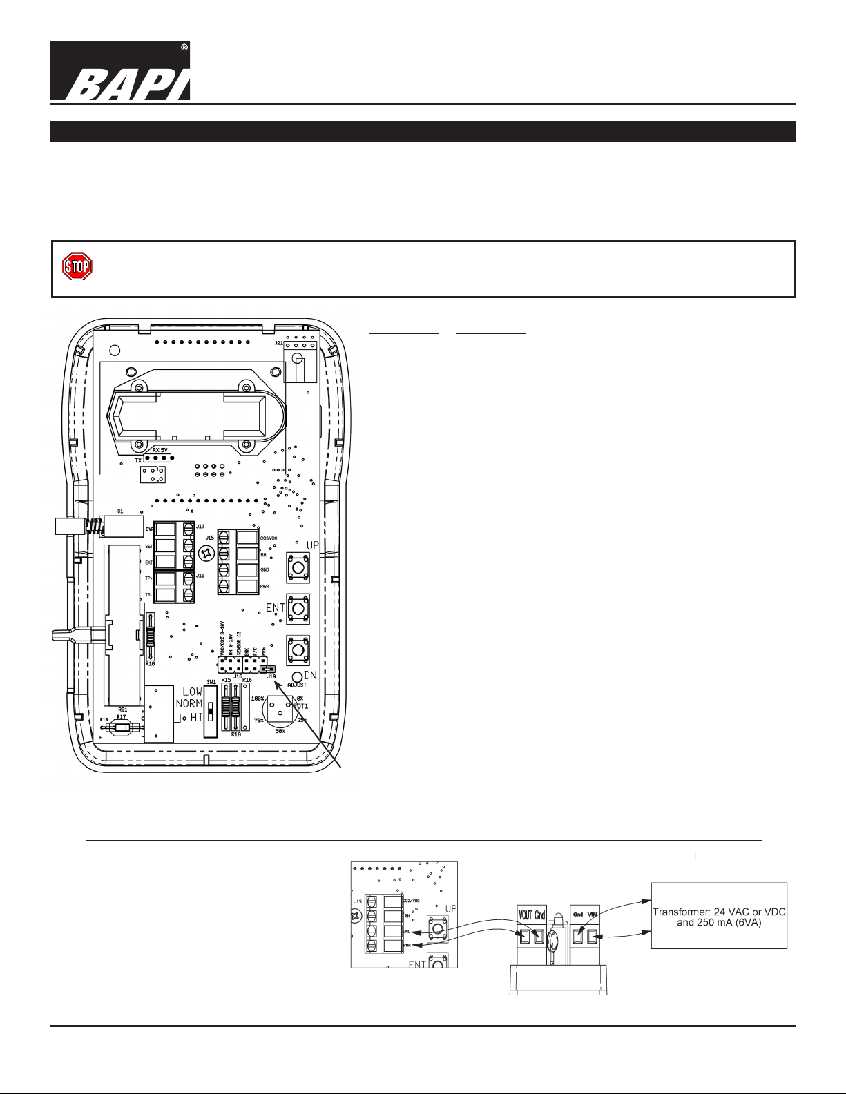
Fig. 1: BAPI-Stat 3 Room CO2 Sensor
The BAPI CO2 Sensor is an accurate and reliable way of incorporat-
ing demand controlled ventilation into a building’s HVAC strategy. It
measures the CO2 in a range of 0 to 2,000 ppm with a eld selectable
output of 0 to 5 or 0 to 10 VDC.
The non-dispersive infrared (NDIR) technology has been optimized
to reduce drift. The sensor is also altitude compensated for long-
term accuracy and stability. Changing air pressure, due to altitude
or weather patterns, can change the output of most CO2 sensors by
as much as 17%. The BAPI unit has a built-in barometric sensor that
continuously compensates the output for accurate readings despite
inclement weather or the altitude of the installation.
The unit can be ordered as CO2 alone, or with optional temperature
sensing, temperature setpoint, occupant override and humidity sens-
ing. The large format display is easy to read and alternates between
the measured values (CO2, Temperature or Humidity). The display is
also eld adjustable between °F or °C and all the displayed values
may be turned on or off by an HVAC technician.
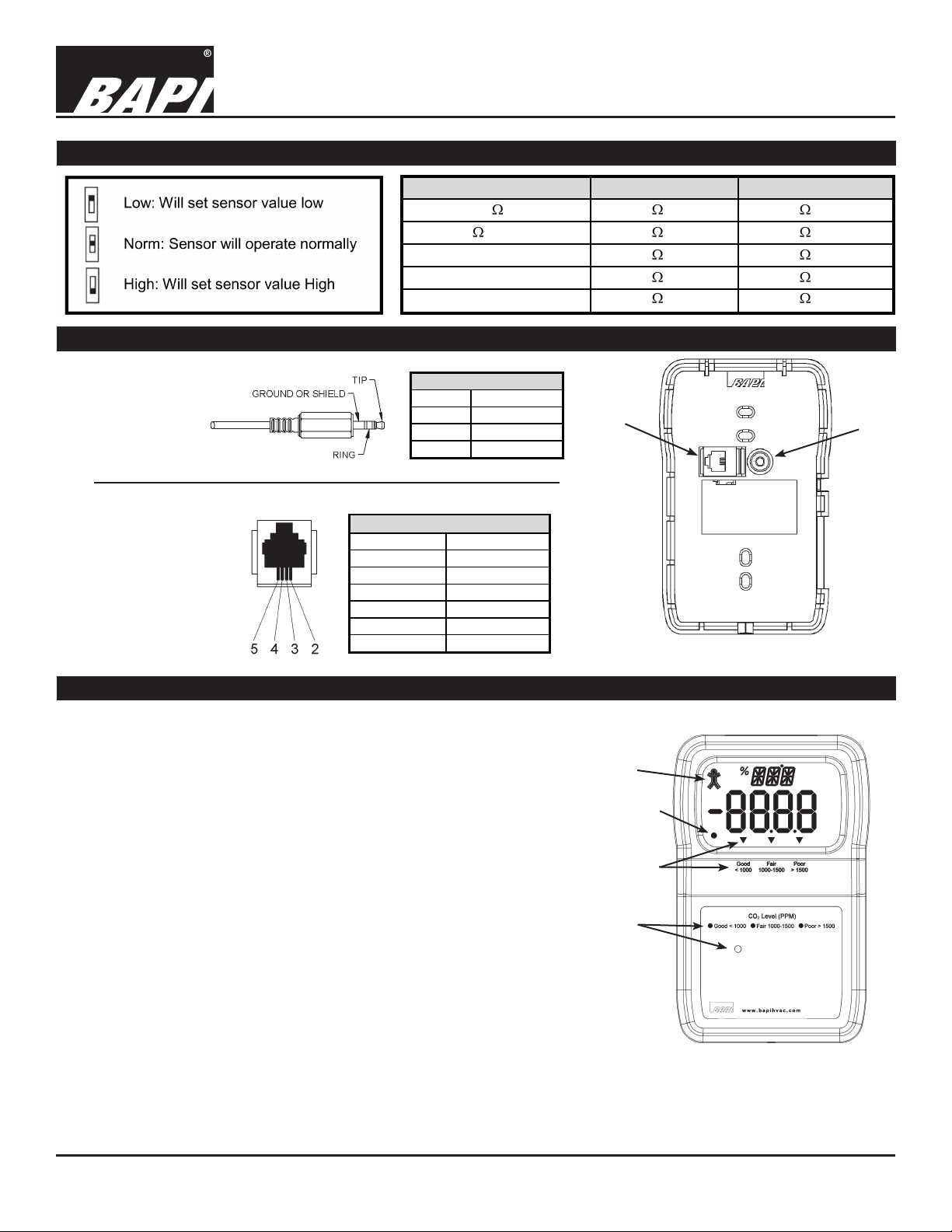
Optional indication of the CO2 level as “Good, Fair or Poor” is avail-
able as a three-color LED on the unit or as an arrow on the display.
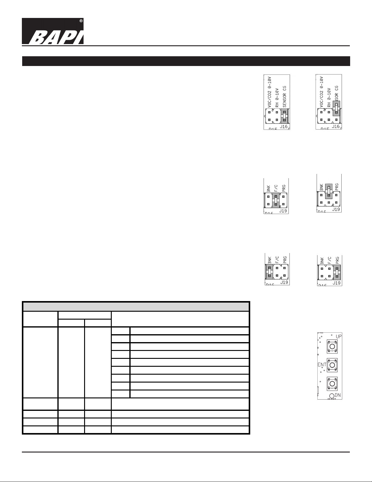
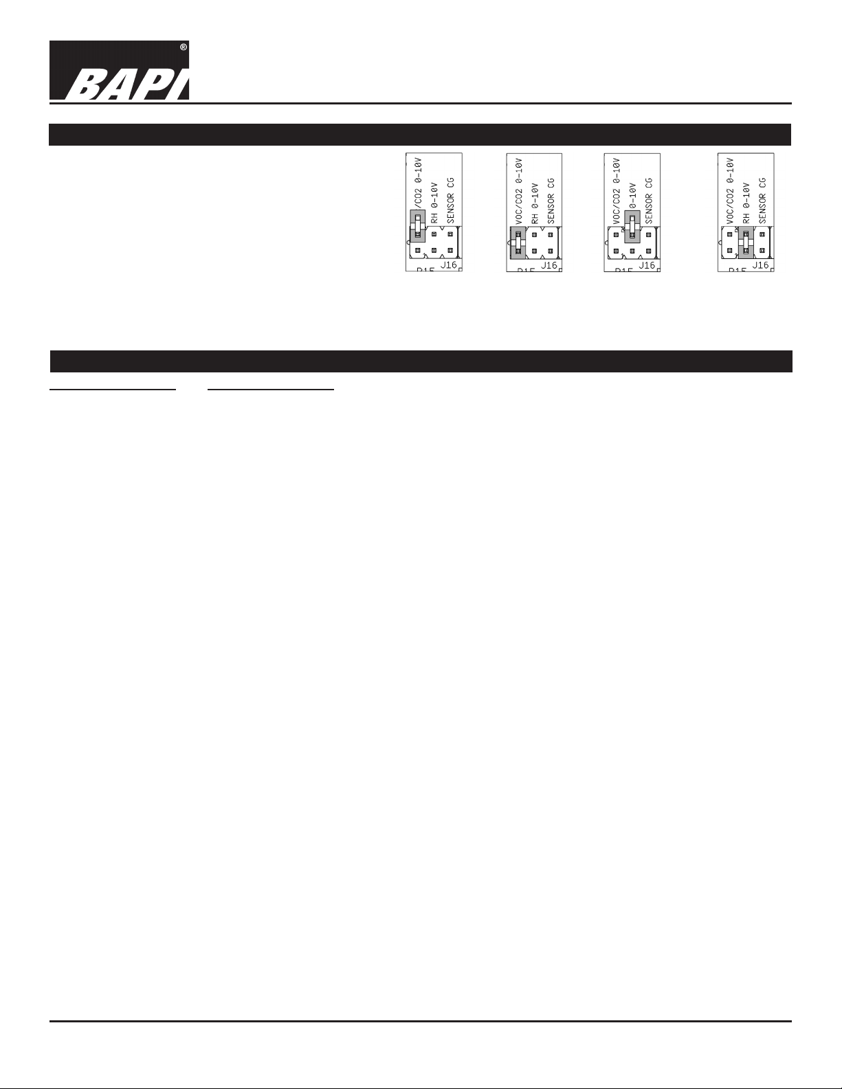
Identication and Overview
Specications
Power for 0 to 5 VDC Outputs:
9 to 35 VDC @ 240mA (9 to 24 VDC recommended)
Power for 0 to 10 VDC Outputs:
15 to 35 VDC @ 240mA (15 to 24 VDC recommended)
Sensing Elements:
CO2 – Single Beam Non-Dispersive Infrared (NDIR)
or Dual Channel NDIR for “24/7” Model
Humidity – Capacitive Polymer ±2% RH Accuracy
Temperature Sensor:
Thermistor, RTD or Semiconductor
Operating Environment:
32 to 122°F (0 to 50°C)
0 to 95%, RH non-condensing
Material ABS Plastic, Material Rated UL94V-O
CO2 Detection Range: 0 – 2000 ppm
Start-Up Time: <2 Minutes
Response Time:
<2 Minutes for 90% step change typical (after start-up)
Mounting: 2”x4” J-Box or drywall – screws provided
Override Output:
Contact ....SPST, 24V AC/DC, 0.5A max
Sensor .....Shorts Out direct temperature sensor
Setpoint ...Contact in parallel, resistive setpoint only
LCD Display:
Main Display: 0.76” 4-digit Numeric Values
Minor Display: 0.34” 3-digit Alpha-Numeric
(PPM, %RH, °F, °C)
Occupancy BAPI Man Icon: (Blk=Occupied)
Measurement Offsets: (Field Adjustable)
±5° (F or C) in 0.1° increments
±5% RH in 0.1% RH increments
CO2 Accuracy:
(Single Channel Automatic Background Calibration model)
400 to 1,250 ppm: ±30ppm or 3% of reading,
whichever is greater
1,250 to 2,000 ppm: ±5% of reading + 30ppm
CO2 Accuracy:
(“24/7” Dual Channel Model)
75ppm or 10% of reading (whichever is greater)
CO
2
Drift Stability (Dual Channel DCD “24/7” Units):
<5% of full scale over life of product.
LED CO2 Level Indicator:
Good, Green < 1,000 PPM
Fair, Orange = 1,000 to 1,500 PPM
Poor, Red > 1,500 PPM
Certications: RoHS
Warranty Period: 5 Years from manufacture date

Installation and Operating Instructions
CO2 Room Sensor in the BAPI-Stat 3 Enclosure
with Common Ground Conguration
Specications subject to change without notice.
26141_ins_room_CO2
2 of 6
rev. 04/27/18
Mounting
Mounting hardware is provided for both junction box and drywall instal-
lation (junction box installation shown).
Note: Screw the 1/26” Allen lock-down screw into the base to open the
case, less chance of losing it this way. Back out the lock-down screw
to secure the cover.
Junction Box
1. Pull the wire through the wall and out of the junction box, leaving
about six inches free.
2. Pull the wire through the hole in the base plate.
3. Secure the plate to the box using the #6-32 x 5/8 inch mounting
screws provided.
4. Terminate the unit according to the guidelines in the Termination
section. (page 3)
5. Mold the foam on the unit’s base to the wire bundle to prevent
drafts. (see note below)
6. Attach Cover by latching it to the top of the base, rotating the cover
down and snapping it into place.
7. Secure the cover by backing out the lock-down screw using a
1/16” Allen wrench until it is ush with the bottom of the cover.
Drywall Mounting
1. Place the base plate against the wall where you want to mount the sensor.
2. Using a pencil, mark out the two mounting holes and the area where the wires will come through the wall.
3. Drill two 3/16” holes in the center of each marked mounting hole, DO NOT punch the holes or the drywall an-
chors will not hold. Insert a drywall anchor into each hole.
4. Drill one 1/2” hole in the middle of the marked wiring area.
5. Pull the wire through the wall and out of the 1/2” hole, leaving about six inches free.
6. Pull the wire through the hole in the base plate.
7. Secure the base to the drywall anchors using the #6 x 1 inch mounting screws provided.
8. Terminate the unit according to the guidelines in the Termination section. (page 3)
9. Mold the foam on the unit’s base to the wire bundle to prevent drafts. (see note below)
10. Attach cover by latching it to the top of the base, rotating the cover down and snapping it into place.
11. Secure the cover by backing out the lock-down screw using a 1/16” Allen wrench until it is ush with the bottom
of the cover.
NOTE: In any wall-mount application, the wall temperature and the temperature of the air within the wall cavity can
cause erroneous readings. The mixing of room air and air from within the wall cavity can lead to condensation, er-
roneous readings and sensor failure. To prevent these conditions, BAPI recommends sealing the conduit leading to
the junction box, lling the junction box with berglass insulation or sealing the wall cavity.
Fig. 2: Mounting to a Junction Box

Installation and Operating Instructions
CO2 Room Sensor in the BAPI-Stat 3 Enclosure
with Common Ground Conguration
Specications subject to change without notice.
26141_ins_room_CO2
3 of 6
rev. 04/27/18
Terminal Function
OVR ............. Override Output (Dry Contact Switch). When
Override switch is pushed this terminal is connected
to the GND terminal.
SET.............. Setpoint output. Referenced to GND terminal.
EXT.............. External occupied LCD indicator is activated by logic
LOW or ground at this terminal, referenced to the
GND terminal.
TP+ & TP- ... Temperature Sensor Output (Resistive Output).
When a jumper is on J16, TP- is connected to the
GND terminal. When the jumper is off of J16, the
temperature sensor is oating.
(Semiconductor TP+ = +, TP- = -)
CO2 / VOC .... Voltage output CO2 Signal (0 to 2,000 ppm)
referenced to the GND terminal.
RH ............... Voltage output Humidity Signal referenced to the
GND terminal.
GND ............. To controller Ground [GND or Common]
PWR ............ Power, referenced to GND
9 to 35 VDC @ 240mA
(9 to 24 VDC recommended) for 0 to 5 VDC Outputs
15 to 35 VDC @ 240mA
(15 to 24 VDC recommended) for 0 to 10 VDC Outputs
Termination
Note: Unit is not ready for
operation until the 10 minute
start-up time has elapsed.
Fig. 3: Circuit Board Note: For proper operation, the
jumper on PRG connector of J19
must be connected by only one leg.
BAPI recommends using twisted pair of at least 22AWG and sealant lled connectors for all wire connections. Larger
gauge wire may be required for long runs. All wiring must comply with the National Electric Code (NEC) and local codes.
Do NOT run this device’s wiring in the same conduit as AC power wiring. BAPI’s tests show uctuating and inaccurate
signals are possible when AC power wiring is in the same conduit as the signal lines. If you are experiencing any of these
difculties, please contact your BAPI representative.
BAPI recommends wiring the product with power disconnected. Proper supply voltage, polarity and wiring
connections are important to a successful installation. Not observing these recommendations may damage the
product and void the warranty.
VC350A or VC350A-EZ
Voltage Converter
(VC350A shown below)
CO2 Sensor
POWERING WITH A BAPI VC350A
VOLTAGE CONVERTER
The CO2 unit requires 240mA of current
to operate correctly. If this is more
current than can be provided by the
controller power output, then the unit
can be powered by a BAPI VC350A or
VC350A-EZ Voltage Converter. Fig. 4: Powering with
a BAPI VC350A

Installation and Operating Instructions
CO2 Room Sensor in the BAPI-Stat 3 Enclosure
with Common Ground Conguration
Specications subject to change without notice.
26141_ins_room_CO2
4 of 6
rev. 04/27/18
Wire Color
Ground Black
Tip White
Ring Red
Table 1: C35 Wiring
Comm Jack Pin Wire Color
1 Not Connected
2 Black
3 Red
4 Yellow
5 Green
6 Not Connected
Table 2: C11 Wiring
Optional Communications Jack Wiring
Fig. 5: Communication Jack Locations
C11 C35
C35
Communication
Jack
(Male jack
shown for clarity)
C11
Communication
Jack
User Operation
The display indicates CO2 in PPM, temperature in °F or °C,
%RH, temperature setpoint in degrees °F or °C and override
using the BAPI Man icon. The three triangle icons are used
with the –ARW option to show CO2 levels.
The main display indicates the numeric value of the quantity
being displayed. The minor display indicates the engineering
units of the value, such as PPM, °F, °C or %RH.
Temperature Setpoint Slidepot: Moving the slidepot enough
to change the setpoint by one degree will display the setpoint
on the main LCD display if equipped with display. The setpoint
display will hold for ve seconds after moving the slide pot.
Override Button: When the override button is pressed on
display units, the BAPI Man icon will display. A dry resistance
of less than 1 ohm appears from the override output (OVR) to
the Ground terminal (GND). Latching the Icon to show that
the system is in override requires that a dry contact on your
controller be used to connect terminal EXT to ground.
Optional CO2 Level Indication via Arrow or 3-Color LED
CO2 level indication is available via a black arrow on the display
or a three-color LED on the logo plate with green for good,
yellow for fair and red for poor.
Optional Test and Balance Switch (SW1)
Sensor Type Low Temp High Temp
1000 RTD 1.02K (41.2°F) 1.15K (101.5°F)
3000 Thermistor 7.87K (39.8°F) 1.50K (106.8°F)
10K-2 Thermistor 30.1K (34.9°F) 4.75K (109.1°F)
10K-3 Thermistor 26.7K (35.9°F) 5.11K (108.4°F)
10K-3(11K) Thermistor 7.32K (43.7°F) 3.65K (105.2°F)
BAPI Man
Icon
Fig. 6: CO2 Unit Indicators
(Shown above with all
optional indicators)
Arrow
Indicators
& Legend
LED
Indicator
& Legend
Note: Both
indicators are
not available
together
“ON” Icon

Installation and Operating Instructions
CO2 Room Sensor in the BAPI-Stat 3 Enclosure
with Common Ground Conguration
Specications subject to change without notice.
26141_ins_room_CO2
5 of 6
rev. 04/27/18
BAPI’s CO2 room sensor comes calibrated and ready to operate. In some
installations the sensor may not match local instrumentation. The technician
adjustment procedure allows °F or °C display units, temperature or humidity
offsets or display information to be changed at any time.
Removing Ground from Temperature Sensor
Some installations may experience erratic temperature readings. A possible
remedy may be to oat the temperature sensor as shown in Figs 7 and 8. Run
wires directly from TP+ and TP- to the controller’s analog input. The VOC/CO2
and RH jumpers are omitted for clarity.
°F or °C Display Units
Figs 9 and gure 10 show the jumper positions for displayed values of Celsius
or Fahrenheit degrees. The jumpers on pins PRG and BNK are omitted for
clarity.
Parameter Offsets & Display Information
Figs 11 and 12 show how to place the unit into eld setup mode. Take the
jumper from the BNK terminals and place it on the PRG terminals. The F/C
jumper is omitted for clarity.
The major display should read P1 and the minor display should read DSP.
Use the UP/DN buttons (See Fig 13) to select the desired page.
Press and release the ENT button to select the desired page.
Use the UP/DN buttons to adjust the desired value
Press and release the ENT button to save the change and return to the page
display.
Adjust another page or place the jumper into normal operation.
Fig. 7: Temp.
Sensor
Grounded
Fig. 8: Temp.
Sensor
Floating
Fig. 9: °F Fig. 10: °C
Fig. 11:
Normal
Operation
Fig. 12:
Programming
Setup
Optional Technician Adjustments
Fig. 13:
Calibration
Buttons
Main Minor
Item Display Action
1 Temperature Only
2 % RH Only
3CO2 Only
4 Temperature and %RH (10 second rotation)
5Temperature and CO2 (10 second rotation)
6%RH and CO2 (10 second rotation)
7Temperature, %RH and CO2 (10 second rotation)
8 Setpoint Display Only
Temperature
Offset P2 TMP
%RH Offset P3 %RH
CO2 Offset P4 CO2
Altitude P5 ALT
±5° in 0.1° increments
±5% RH in 0.1% RH increments
±100 ppm in 1 ppm increments
Effective Pressure Altitude (display only, no adjustment)
Table 4: Parameter Offsets & Display Information
Parameter Display Adjustment
Display Options P1 DSP

Installation and Operating Instructions
CO2 Room Sensor in the BAPI-Stat 3 Enclosure
with Common Ground Conguration
Specications subject to change without notice.
26141_ins_room_CO2
6 of 6
rev. 04/27/18
The CO2 outputs may be eld congured for 0
to 5 VDC or 0 to 10 VDC outputs at any time.
Set the jumpers on J16 as shown in Figs 12
and 13.
The humidity outputs may be eld congured
for 0 to 5, 1 to 5, 0 to 10 or 2 to 10 VDC outputs
at any time. Set the jumpers on J16 as shown
in Figs 14 and 15.
Note: The jumpers on the pins not being
described are omitted for clarity on the gures
at right.
Output Selection
Diagnostics
Possible Problems: Possible Solutions:
General troubleshooting Determine that the input is set up correctly in the controller's and building automation software.
Check wiring at the sensor and controller for proper connections. If there is corrosion, clean off
the corrosion, re-strip the interconnecting wire and reapply the connection. In extreme cases,
replace the controller, interconnecting wire and/or sensor.
Label the terminals that the interconnecting wires are connected to at the sensor end and the
controller end. Disconnect the interconnecting wires from the controller and the sensor. With
the interconnecting wires separated at both ends measure the resistance from wire-to-wire with
a multimeter. The meter should read greater than 10 Meg-ohms, open or OL depending on the
meter you have. Short the interconnecting wires together at one end. Go to the other end and
measure the resistance from wire-to-wire with a multimeter. The meter should read less than 10
ohms (22 gauge or larger, 250 feet or less). If either test fails, replace the wire.
Check power supply/controller voltage supply for proper voltage (see specications)
Incorrect CO2 Wait 15 minutes after a power interruption.
Check all software parameters
Determine if the sensor is exposed to an external environment different from the room (conduit draft)
If the sensor is reading consistently high, make sure that the power supply to the unit can provide
240mA. A low power situation will cause high CO2 readings.
Note: If the CO2 sensor has consistently given high PPM readings for over 5 days, it will take up
to 14 days for the readings to return to normal.
Incorrect Humidity Check all software parameters
If available, check the sensor against a calibrated instrument such as a hygrometer
Determine if the sensor is exposed to an external environment different from the room (conduit draft)
Incorrect Temperature Check the wires at the sensor and controller for proper connections.
Check the Temperature Output of the unit. Disconnect the temperature sensor’s wire (Terminals
TP+ & TP-) and measure the temperature sensor’s resistance across the sensor output pins with
an ohmmeter. Put the ohmmeter’s black lead on Terminal TP- and the red lead on Terminal TP+.
Compare the temperature sensor’s resistance to the appropriate temperature sensor table on the
BAPI website. (Go to www.bapihvac.com; click on “Resource Library” and “Sensor Specs”, then
click on the sensor type you have.) If the measured resistance differs from the temperature table
by more than 5%, call BAPI technical support.
Determine if the sensor is exposed to an external environment different from the room (conduit or
wall cavity draft)
Fig. 14:
CO2 Output
0 to 5 VDC
Fig. 15: CO2
Output 0 to
10 VDC
Fig. 16: %RH
Output 0 to 5
or 1 to 5 VDC
Fig. 17: %RH
Output 0 to 10
or 2 to 10 VDC
Table of contents
Other BAPI Accessories manuals