manuals.online logo
Brands
  1. Home
  2. •
  3. Brands
  4. •
  5. BAPI
  6. •
  7. Media Converter
  8. •
  9. BAPI VC3000 series User manual

BAPI VC3000 series User manual

Voltage Converters
9532_ins_ps_vc
Building Automation Products, Inc., 750 North Royal Avenue, Gays Mills, WI 54631 USA
Tel:+1-608-735-4800 • Fax+1-608-735-4804 • E-mail:[email protected] • Web:www.bapihvac.com
Specications subject to change without notice.
Installation and Operation Instructions
rev. 01/23/13
Rectication Settings
The AC to DC rectication may be set to
either full wave or half wave by attaching
the supplied clip to terminal block J2.
Attach the clip to J2 for full wave. Do not
use the clip for half wave. Note: If the
VC3000 is ordered FW the clip is installed
on J2. If the VC3000 is ordered HW, the
clip is taped to the bottom of the metal
plate.
When multiple devices (such as
controllers, actuators, and the VC3000)
are connected to one transformer, the full
wave/half wave rectication of all devices
must match. For example, if the controllers
being used are half wave and connected
to the same transformer that supplies the
voltage converter board, then do not use
the clip on J2. Always remove 24 VAC
power before changing the clip position.
Clip Settings
VC 3000 Voltage Converter
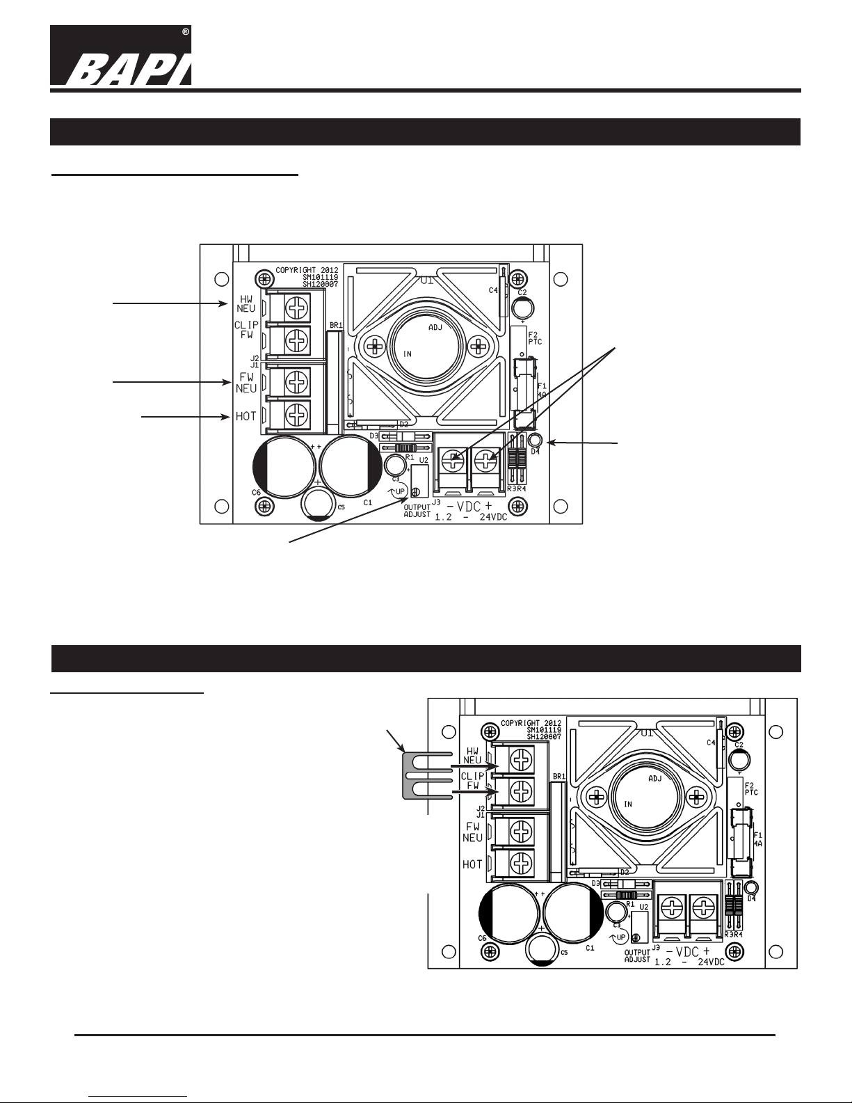
The VC3000 series voltage converter is powered with 24 VAC. Wire as shown in Fig. 1 below. When properly wired,
the red Power Output LED will light.
Output Terminal Block
1.2 to 24 VDC Output
Note: The voltage converter output is set
at the factory, but can be adjusted in the
eld. Please refer to the “Voltage Output
Adjustment” instructions on page 2 of
this document.
Output Adjust Trim Potentiometer
Factory Set at 24 VDC
Red Power Output LED
Termination
24VAC Hot
NOTE: The selection of the
“Hot” and “Neutral” wires
for the 24VAC input is very
important.
24VAC
Full Wave
Neutral
24VAC
Half Wave
Neutral
Fig. 1: VC3000
Fig. 2: Attach Clip for Full Wave Rectication
Attach Clip to
the Terminal
Block J2 for
Full Wave
Rectication
Clip
Voltage Converters
9532_ins_ps_vc
Building Automation Products, Inc., 750 North Royal Avenue, Gays Mills, WI 54631 USA
Tel:+1-608-735-4800 • Fax+1-608-735-4804 • E-mail:[email protected] • Web:www.bapihvac.com
Specications subject to change without notice.
Installation and Operation Instructions
rev. 01/23/13
PROBLEMS:
No voltage on output
Voltage on output is reading low or high
POSSIBLE SOLUTIONS:
- Verify that input voltage is correct
- If the unit has a replaceable glass fuse, check it for continuity. If a
replacement fuse is needed, replace it wth a 4.0 A fuse.
*Loading higher value fuses may cause damage and void
warranty
- If the unit has a resettable fuse and the fuse is tripped, it may
be an output short circuit or overload. Remove input power and
determine the problem. When the problem is corrected, reapply
power to the unit.
- Verify that input voltage is correct
- Verify that the “Output Adjust” trim potentiometer is set correctly
using the “Voltage Output Adjustment” procedure shown below
- Check wiring for proper termination
VC3000 series voltage converters have an adjustable output of 1.2 to 24 VDC. Adjust output to a custom
voltage as follows:
1. Using a voltmeter, connect the positive lead to the “+” and the negative lead to the “-” of the terminal block
labeled “VDC”.
2. With a small, straight bladed screwdriver, adjust the “Output Adjust” trim potentiometer (located next to the
“VDC” terminal block) until the voltmeter reads the desired output.
3. Disconnect the voltmeter
4. Connect the load.
5. If exact output voltage is required, measure the voltage out under load and adjust accordingly.
Voltage Output Adjustment
Diagnostics
Half Wave
Input Voltage ............18 to 28 VAC
Input Current ............3.1 Amps AC max @ 24 VAC (75 VA)
Output Voltage .........1.2 to 24 VDC @ 1.5 Amps max
Output Ripple ...........20 mV max
Full Wave
Input Voltage ............18 to 28 VAC
Input Current ............4.1 Amps AC max @ 24 VAC (98 VA)
Output Voltage .........1.2 to 24 VDC @ 2.5 Amps max
Output Ripple ...........25 mV max
Diagnostics

Popular Media Converter manuals by other brands

TKH security EVE ONE-PoE quick start guide

TKH security

TKH security EVE ONE-PoE quick start guide

Equip VS0201 user manual

Equip

Equip VS0201 user manual

SMSL M100 MKII user manual

SMSL

SMSL M100 MKII user manual

B&B Electronics RS-232 to Ethernet Converter ES1A product manual

B&B Electronics

B&B Electronics RS-232 to Ethernet Converter ES1A product manual

Transition Networks FBRM1XXX-1XX manual

Transition Networks

Transition Networks FBRM1XXX-1XX manual

Sisyph SMB10 user guide

Sisyph

Sisyph SMB10 user guide

Audiolab 6000N Play user manual

Audiolab

Audiolab 6000N Play user manual

Uhlenbrock Elektronik 74 400 user manual

Uhlenbrock Elektronik

Uhlenbrock Elektronik 74 400 user manual

Lem Elettronica DM200HD user guide

Lem Elettronica

Lem Elettronica DM200HD user guide

Baumer HUBNER POG 10 Series Mounting and operating instructions

Baumer

Baumer HUBNER POG 10 Series Mounting and operating instructions

Shinybow USA SB-3879 instruction manual

Shinybow USA

Shinybow USA SB-3879 instruction manual

SECOMP 14.99.3523 user manual

SECOMP

SECOMP 14.99.3523 user manual

M-system JFR2 instruction manual

M-system

M-system JFR2 instruction manual

Z3 Technology Z3-DME-01 User instructions

Z3 Technology

Z3 Technology Z3-DME-01 User instructions

Optex REDWALL PIE-1 installation instructions

Optex

Optex REDWALL PIE-1 installation instructions

StarTech.com MCM1110MMLC instruction manual

StarTech.com

StarTech.com MCM1110MMLC instruction manual

Patton electronics 1104 Series user manual

Patton electronics

Patton electronics 1104 Series user manual

moon 100 D owner's manual

moon

moon 100 D owner's manual

manuals.online logo
manuals.online logoBrands
  • About & Mission
  • Contact us
  • Privacy Policy
  • Terms and Conditions

Copyright 2025 Manuals.Online. All Rights Reserved.