BAQ kaloMAX User manual

kaloMAX
Manual
Version 1.01

Table of contents
1 Introduction.......................................................................................................................................3
2 Installation.........................................................................................................................................4
3 General handling..............................................................................................................................5
4 Programming....................................................................................................................................
5 Doing a measurement......................................................................................................................8
6 Analysis of the spherical cap ..........................................................................................................9
6.1 Plane samples ..........................................................................................................................9
6.2 Cylindrical samples................................................................................................................10
Examples of measurements..........................................................................................................12
8 Maintenance of the unit.................................................................................................................13
8.1 Cleaning..................................................................................................................................13
8.2 Replacement of the driving belt............................................................................................13
8.3 Fuses.......................................................................................................................................13
8.4 Replacement of the driveshaft...............................................................................................13
8.5 Replacement parts..................................................................................................................13
9 Technical data.................................................................................................................................14

BAQ kaloMAX Manual
1 Introduction
The kaloMAX is a spherical cap grinder for the determination of the layer thickness of coatings
and layer systems.
A steel ball lies on a revolving shaft and also on the angular positioned sample. A small
spherical cap is ground through the layer on the sample into the base material by means of the
ball and a little abrasive slurry. On plane samples, the cap is circular. The layer thickness can
be calculated from the difference of the cap diameter at the surface of the sample and the
diameter of the boundary between layer and base material. These diameters can be measured
with a microscope. The diameter of the grinding ball, which goes into the calculation, is
known. This purely geometrical method for determination of layer thickness can be extended
to layer systems.
Because most layers are in the range of µm, the spherical caps are very small. To obtain clearly
visible limits, great importance was attached to the guidance of the ball on the driveshaft and
to the bearing of the shaft, so that horizontal and vertical movements of the ball during the
grinding cycle are avoided.
Different combinations of revolutions per minute and grinding period can be saved under a
program number. This allows quick and reproducible measurements on different types of
layers.
Page 3

BAQ kaloMAX Manual
2 Installation
The kaloMAX has to be located in a place, where no vibrations or agitations can occur during
the measurement.
The current supply is done by a wide range power supply with an input voltage range of 85 to
264 V and a frequency of 4 to 63 Hz.
Note: Due to the CE specifications the ranges stated at the type label are shortened by 10% at
the top and bottom.
Steel balls of appropriate diameter and diamond grinding paste are needed for operation.
The greater the steel ball, the flatter the spherical cap. I.e. with greater balls, the diameters
differ more and that results in a greater accuracy of measurements. On the other hand, more
material has to be ground away to obtain the same depth of the cap, so the time cost is greater
with greater balls. Usually, a ball diameter of 20 to 25 mm is a good compromise.
The grit size of the diamond grinding paste must be chosen according to the layer thickness. If
the paste is coarse, the grinding surface pattern is worse and the limits of a thin layer are no
more visible. Mostly a grit size of 1µm is adequate.
Polycristalline diamonds results in a slightly higher rate of material removal and also in
somewhat better grinding surface patterns.
Page 4

BAQ kaloMAX Manual
3 General handling
Power switch / fuses
The power switch and the fuses ( 2 x T 1 A ) are located at the back side of the
unit between power connector and power switch.
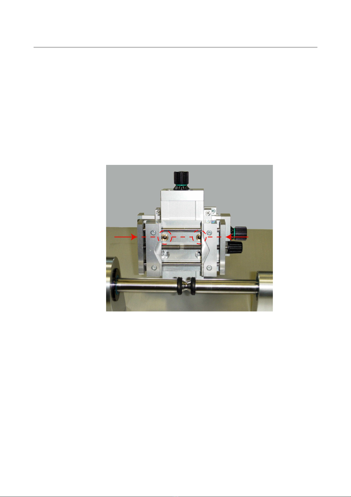
Specimen holder
The samples are clamped into a small vice. The upper part of the vice jaws can
be turned to fit round or straight samples. This parts can be replaced in case of
damage.
Compound table
The specimen holder is mounted to a compound table with a movement range
of 25 x 25 mm.
Movable stand
The adjustment to different ball diameters or sample thickness is done by
moving the whole unit of specimen holder and compound table. To move the
unit, the fixing screws at the back side have to be loosened.
LED readouts
The LED readouts show the actual values for the number of revolutions (rpm),
the grinding period and the selected program.
After power up, the last parameters are active.
When the motor is started, the remaining grinding time will be displayed
continually.
Buttons
The 'START'-button starts the grinding procedure using the active parameter for
revolutions and grinding period.
The 'STOP'-button stops the grinding. The motor stops immediately.
The 'ENTER'-button is used to set up a new program.
By means of the ↑↓ buttons beneath the readouts for revolutions and grinding
period, the corresponding values can be changed stepwise.
When any parameter is changed, the program number is set to '-'. A test run can
be done by pressing the start button.
Page 5

BAQ kaloMAX Manual
Option removable specimen holder
The vice holding the sample can be removed from the compound table. With a
microscope it can be checked, if grounding is complete and the base material is
visible.
If the grinding process shall be continued, the vice can be replaced to the
compound table. The precision guides assure that the grinding process is
continued at the former position.
It is important not to cant the specimen holder when removing or attaching it.
Therefore the specimen holder should be held at the outer sides on the same
level as the guides (see figure below).
Page 6

BAQ kaloMAX Manual
4 Programming
kaloMAX provides the facility to save frequently used combinations of revolutions and grinding
period. The combinations are identified by a program number and can be quickly recalled
when required.
After power up, the last program is active. By means of the ↑↓ buttons beneath the readout for
the program number, the desired program can be selected. The parameter for revolutions and
grinding period according to the selected program will be displayed immediately.
Building a new program:
•Adjust the number of revolutions and the grinding period.
•Press the 'ENTER' button.
•Select the desired program number. The decimal point behind the number shows, that
the programming is not yet completed. All buttons but the 'ENTER' button are disabled.
•Press 'ENTER' to complete the programming. The decimal point behind the program
number disappears.
Page

BAQ kaloMAX Manual
5 Doing a measurement
The result of the grinding process depends on the following factors:
•grinding paste
•number of revolutions
•grinding period
•diameter of the ball
•normal force exerted by the ball
The weight of the ball will be taken up by the shaft and the sample. The greater the distance
between sample and shaft, the greater is the normal force on the sample.
Clamp the sample carefully into the sample holder. Adjust the sample and place the (clean!)
ball. Then put a small amount of the grinding paste on the top of the ball. See that the paste
does not slide down to the traction rings on the driveshaft.
Select the desired program or set the measuring parameter.
Start the grinding procedure. The grinding period will be counted down to zero. Neither the
ball nor the driveshaft may be touched during the grinding process.
When the grinding process is complete, remove and clean the ball. The diameter of the
spherical cap can be measured after cleaning the sample.
Page 8

BAQ kaloMAX Manual
6
Analysis of the spherical cap
6.1
Plane samples
Legend
h desired layer thickness
R radius of the ball
T total penetration depth of the ball
t depth of penetration in the base material
D diameter of the spherical cap at the surface of the sample
d diameter of the boundary between coating and base material
Page 9

BAQ kaloMAX Manual
The total penetration depth of the ball is:
T=R
R
2
D
2
4
The depth of penetration in the base material is:
t=R
R
2
d
2
4
The thickness of the layer results from the difference:
h=Tt
h=
R
2
d
2
4
R
2
D
2
4
If the layer is very thin and the spherical cap is ground into the base material only a little, the
diameters D and d are very small compared to the radius of the ball. In this case the equation
can be simplified to:
h=D
2
d
2
8R
This formula shows, that the accuracy of layer thickness measurement by means of spherical
cap grinding depends on the accurate measurement of the two diameter D and d, because the
error of R is less then 1 ‰. Furthermore the meticulous measurement of the two diameters is
important because the square of these items is used in the calculation. In general, the spherical
cap should not be ground too deep into the base material in order to achieve high accuracy.
6.2 ylindrical samples
When the sample is cylindrical, the shape of the spherical cap is elliptic instead of circular. The
calculation of layer thickness can be done with the same equations as for plane samples but it
is essential to take D and d from the longitudinal axis of the ellipse.
Page 10

BAQ kaloMAX Manual
7 Examples of measurements
Coating: TiN
Revolutions per minute: 600 1/min
Grinding period: 25 s
Ball diameter: 30 mm
Layer thickness: 2.5 µm
Coating: TiCN
Revolutions per minute: 600 1/min
Grinding period: 25 s
Ball diameter: 30 mm
Layer thickness: 2.9 µm
Page 11

BAQ kaloMAX Manual
8 Maintenance of the unit
8.1 leaning
When cleaning the kaloMAX, take care that no liquid is spilled into the inside of the unit. The
upper side is not completely sealed.
8.2 Replacement of the driving belt
If the driving belt has to be changed because of insufficient traction, this can be done without
opening the unit:
•Remove the cover of the left bearing.
•Remove the driving belt.
•Pass the new driving belt through the slot in the cover plate
and put it around the lower drive wheel (B).
•Put the driving belt around the drive wheel of the shaft(A).
The belt is guided over the inner side of the tension pulley (C).
•Attach the cover to the left bearing.
8.3 Fuses
Two 1 A delay-action fuses are placed in the power supply unit (double pole fuse protection).
8.4 Replacement of the driveshaft
If the traction rings on the driveshaft are damaged, it is best to replace the whole shaft,
because the tractions rings can only be trimmed for exact running when mounted on the shaft.
The cover of the left bearing has to be removed. After releasing the screws on both sides of
the driveshaft, the whole unit including the bearings can be pulled out to the left.
8.5 Replacement parts
Order No.
Driving belt O-Ring 85 x 3 50-113
Driveshaft complete with trimmed traction rings, in exchange 50-112
Fuses T 1 A
Page 12

BAQ kaloMAX Manual
9 Technical data
Input voltage range 85 – 264 VAC
Input frequency range 4 – 63 Hz
Clamping range for plane samples 50 mm
Clamping range for round samples Ø 3 - 30 mm
Clamping jaws for other dimensions available
on request
Compound table travel 25 x 25 mm
Ball diameter 15 – 30 mm
Incline of sample level 60 degree
Number of revolutions of the driving shaft 100, 200, 300, 400, 500, 600, 00, 800, 900, 1000
Grinding period 5, 10, 15, 20, 25, 30, 35, 40, 45, 50, 55, 60, 0, 80,
90, 100, 110, 120, 150, 180 s
Dimensions 300 x 295 x 235 mm (B x T x H)
Page 13

BAQ GmbH
Automatisierung und
Qualitätssicherung
Hermann-Schlichting Str. 14
D – 38110 Braunschweig
Phone +49 - 530 / 95102 -0
Fax +49 - 530 / 95102 -20
www.baq.de
Table of contents