Bend-Tech Dragon A400 User manual
A400
Part 1 of 1
Plasma Cutting Guide
Revision 3 | English ©2020 Bend-Tech LLC

ii Bend-Tech Dragon A400
Plasma Cutting Guide
©2020 Bend-Tech LLC
All rights reserved. The information in this manual is subject to change without notice.
Bend-Tech LLC strives to produce the most complete and accurate information regarding
its products. We are constantly working to improve and advance our products to increase
performance, user satisfaction and experience. Bend-Tech LLC assumes no responsibility for
errors or omissions regarding this manual. Bend-Tech LLC assumes no liability for damages
resulting from the use of the information contained in this publication.

iiiBend-Tech Dragon A400 Plasma Cutting Guide
Dragon A400
Plasma Cutting Guide
Revision 3
English
Original Instructions
July 2020
Bend-Tech, LLC
729 Prospect Ave.
Osceola, WI 54020 USA
(651) 257-8715
www.bend-tech.com

iv Bend-Tech Dragon A400
Plasma Cutting Guide
Covering Bend-Tech Dragon
Bend-Tech, LLC provides a limited warranty on all new Dragon machines that are
manufactured directly or under license by Bend-Tech, LLC, and sold by Bend-Tech, LLC or its
approved distributors.
Warranty Coverage
Each Bend-Tech Dragon machine is warrantied by the manufacturer against defects in material
workmanship for 12-months. The warranty period commences upon delivery of the Dragon
machine to the customer’s facility.
Repair or Replacement Only
The Manufacturer’s sole liability, and the Customer’s exclusive remedy under this warranty
shall be limited to repairing or replacing the defective part. Repair or replacement of parts
is at the sole discretion of the manufacturer. The Customer is responsible for warranty parts
installation. Bend-Tech does not provide warranty service labor.
Limits
This warranty does not cover components subject to wear due to normal use of the machine
such as belts, lights, tooling etc. This warranty is void if Bend-Tech, LLC has determined any
failure is the result of mishandling, abuse, misuse, improper installation, improper storage,
Software
Dragon software is covered by a 2-year maintenance plan from the purchase date of the
Dragon A400 machine. After the 2-year maintenance plan is expired, the Customer can
purchase a maintenance plan. A maintenance plan will ensure the customer always has
the newest version of Dragon software. The maintenance plan is critical to keeping Dragon
software updated with the newest capabilities possible, and is critical to the servicing of the
machine. Bend-Tech, LLC will contact the Customer regarding updates to the maintenance
plan within 1-month of expiration. Contact Bend-Tech Support to ensure software is up to date:
Limited Warranty

vBend-Tech Dragon A400 Plasma Cutting Guide
Any questions or concerns regarding this manual can be directed to Bend-Tech, LLC
representatives via the Dragon website, www.bend-tech.com. Click Contact in the menu bar for
communication options and send your comments to the Dragon Customer Service department.
Online Resources
• https://www.youtube.com/user/bendtech2020
• http://www.bend-tech.com/wiki7
• http://www.bend-tech.com
• https://www.facebook.com/2020ssi
• https://www.instagram.com/bend_tech
Customer Service
Congratulations on your purchase of the world’s best CNC plasma tube and pipe cutting
machine, the Dragon A400. Bend-Tech, LLC places great pride in customer satisfaction and it
our support is a key factor in your success.
Contact Us
You can contact Bend-Tech, LLC customer service at 651-257-8715. Our support hours are
mailing address is: Bend-Tech LLC, 729 Prospect Ave., Osceola, WI 54020, U.S.A..
Customer Satisfaction Commitment
vi Bend-Tech Dragon A400
Plasma Cutting Guide
This manual contains important statements that are called out from the regular text with an
associated signal word: “Danger,” “Warning,” “Caution,” or “Note.” Each of these signal words
is accompanied by its own icon. These signal words and icons indicate the severity of the
condition and the warning. The machine operator should familiarize themselves with these
warnings and read the statements before operating the machine.
Denitions & Examples
Danger
Danger indicates a serious condition that could cause severe injury or death to the operator or
bystanders if the instructions are not followed.
Warning
A Warning indicates there is a possibility for minor injury if the instructions are not followed
correctly.
! Danger !
Exceeding the material weight limit of the Dragon A400 can result in serious injury
to the operator and/or bystanders.
! Warning !
Due to the extreme temperatures that result from the plasma cutting process, parts
cooled in water in the parts catcher can still be extremely hot. Always use caution
when handling newly-cut parts.
Warnings
Example
Example
viiBend-Tech Dragon A400 Plasma Cutting Guide
Caution
Caution warns the operator that minor injury or machine damage could occur if instructions are
being performed.
Note
! Caution !
the Dragon A400.
Water Cooling system greatly reduces smoke and vapor emitted by the machine.
Bend-Tech recommends use of the Water Cooling system whenever possible.
Example
Example

viii Bend-Tech Dragon A400
Plasma Cutting Guide
Glossary
Glossary
A400
Indicates machine with 400-lb weight limit.
Axis
Bend-Tech 7X
Machine design software - CAD.
BOB
Breakout Board.
Material Support Lifter
The Material Support Lifter supports
material to reduce sag.
Chuck
Located on the Trolley, the Chuck
holds the material so it can be moved
forward, backward and rotated.
Control Box
Connects Dragon Software Suite
to the Dragon A400.
Coolant Tray
Cools cut parts as they are produced.
Drive Belt
The X Motor uses the Drive Belt to power the
Trolley along the Rail. The Drive Belt is mounted
stationary along the length of the machine.
Drive Belt Pulley
Located on the X Motor, it works in
conjunction with the Drive Belt to
power the Trolley along the Rail.
E-Stop
Emergency stop.
ESS
Ethernet Smooth Stepper (Control Board).
Ethernet
System for connecting multiple
computers via a Local Area Network.
Front Gate
The Gate supports the material at the
front of the machine. It consists of two
sets of self-centering roller jaws.
Gate Lead Screw
Controls operation and adjustment of the Gate.
Interface
Any particular screen display generated
by Bend-Tech software.
Mach3
Machine driver software.
Parts Catcher
The parts catcher is placed at the front of
the machine to catch parts as they are cut.
Rail
The Rail is the main structure of the Dragon
A400. The Trolley rides on the Rail.
Tail
The Tail is located at the opposite end of
the Head of the machine. The Tail arrives
pre-assembled. The X Axis homing sensor,
Drive Belt Adjustment Block and E-Stop
are located at the Tail of the machine.
Toolhead
Operates the Marker, Engraver and Torch.
Trolley
The Trolley rides on the Rail, and carries
the Chuck forward and backward along
the length of the Rail Support Beam.

ixBend-Tech Dragon A400 Plasma Cutting Guide
Contents
Contents
Limited Warranty .....................iv
Customer Service.................... v
Customer Satisfaction
Commitment............................. v
Warnings ..................................vi
Glossary ..................................viii
Contents...................................ix
01
Consumables.......................... 11
Overview .........................11
Consumables in Order of Assembly.....11
Consumables Parts List ............. 12
Inspecting and Changing
Consumables ..................... 12
Nozzle........................ 12
Electrode. . . . . . . . . . . . . . . . . . . . . . 12
Swirl Ring ..................... 13
Retaining Cap.................. 13
Shield Cap .................... 14
Signs that Consumables Need
Replacing ........................ 14
Signs of a Bad Electrode ......... 14
Signs of a Bad Nozzle ........... 14
Maximizing Consumables ........... 15
Normal vs. Fine Cut Consumables.. 15
Cutting Speed.................. 15
Gas Supply .................... 15
Torch Mounting ................. 16
Cut Settings ................... 16
Kerf Width..................... 16
Torch Maintenance .............. 17
Cut Charts ....................... 18
Cutting Speed ................. 18
02
Cutting Charts......................... 19
Before Using these Charts........... 19
45 AMP: Mild Steel................. 20
65 AMP: Mild Steel................. 21
85 AMP: Mild Steel................. 22
Additional Cutting Feed Rates for
65/85 Amp: Mild Steel............ 23
03
Troubleshooting ..................... 25
Diagnosing Cutting Issues ........... 25
Cope at Both Ends of the Tube are
not the Same Rotation ........... 25
Cut Quality Issues. . . . . . . . . . . . . . . 26

xBend-Tech Dragon A400
Plasma Cutting Guide
Contents
Round Holes are Coming Out Oval . 26
Machine Cutting and then Returning to
Previous Engraving. . . . . . . . . . . . . . 26
Material....................... 26
Jagged Cuts ................... 27
Torch Not Firing ................ 27
Torch Colliding with Material....... 27
04
Plasma System Gas Supply .. 29
Plasma System Gas/Air Supply ....... 29

11Bend-Tech Dragon A400 Plasma Cutting Guide
Consumables
01
01
Consumables
Overview
Bend-Tech recommends reading the Hypertherm Operator Manual (or operator manual for
whatever brand plasma cutting machine is being used with the Dragon machine) and using
the consumables recommended for mechanized cutting. The Hypertherm unit comes with
shielded consumables. Shielded consumables protect the nozzle and minimize any damage
that can result from slag during the piercing process. Bend-Tech recommends using shielded
consumables with the Dragon A400 whenever possible.
Ensure plasma machine settings are correct for the type of cutting being performed.
Consumables will typically last 3-5 hours of “arc on” time in a mechanized cutting setting.
Consumable life can vary depending on the type of cutting being performed, quality of air
supply, machine settings, type of material being cut and numerous other factors. It is important
to inspect consumables on a regular basis.
Consumables in Order of Assembly
Shield
Retaining Cap Nozzle Electrode Swirl Ring
12 Bend-Tech Dragon A400
Plasma Cutting Guide
Consumables
01
Consumables Parts List
Inspecting and Changing Consumables
It is recommended the Operator change the electrode and nozzle at the same time. This
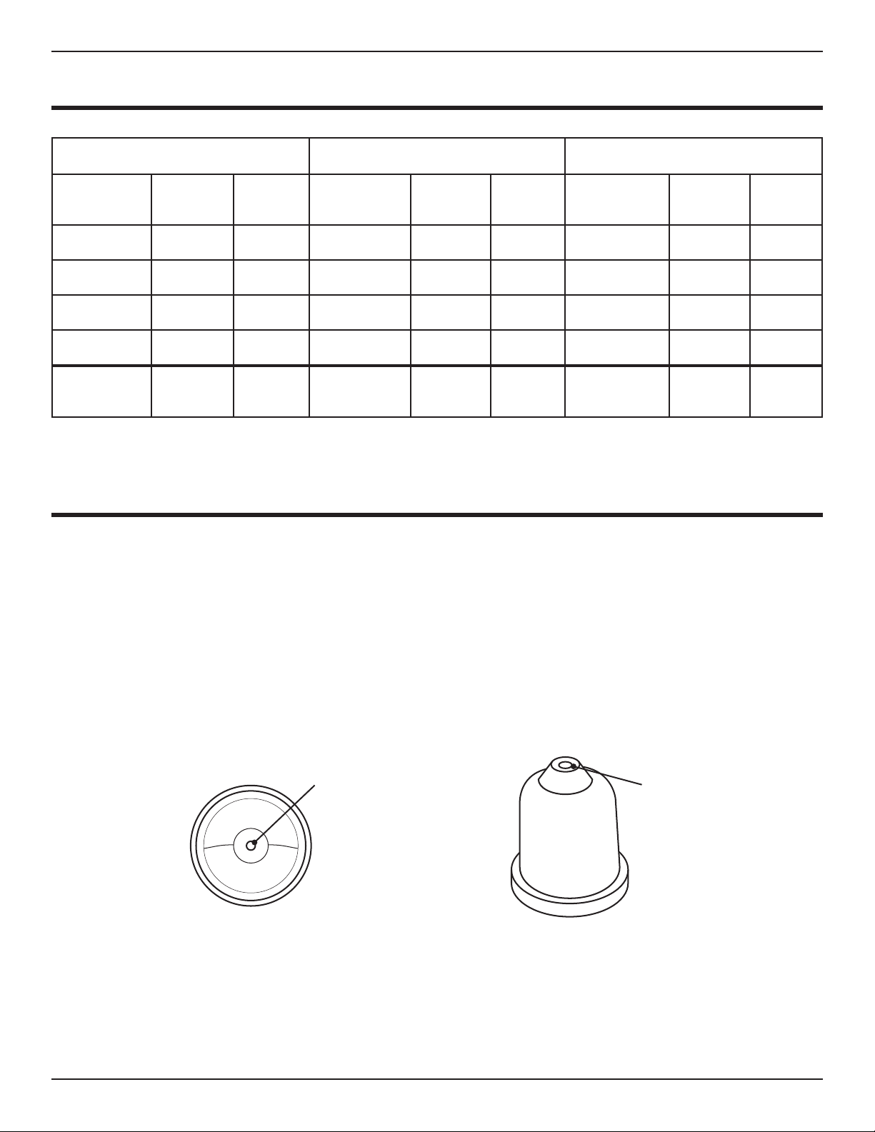
Nozzle
an uneven cut. Often the Operator can conduct a visual inspection of the nozzle to determine
if it is worn out. Also check the cuts for excessive slag and dross. Inspect the nozzle to ensure
it is free of slag. Inspect the inside of the nozzle for out of round or inconsistencies, nicks or
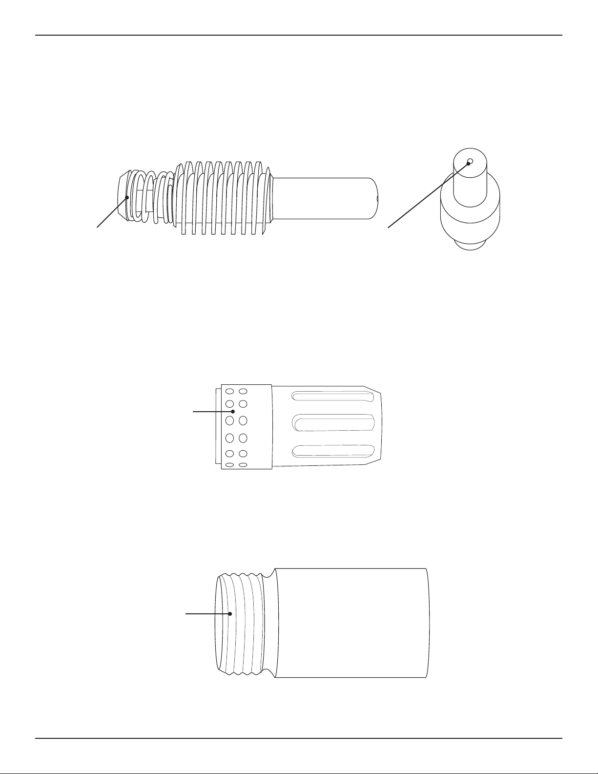
Electrode
The Operator can determine electrode life by measuring pit depth. Pit depth is the distance
from the surface of the copper electrode piece to the halfnium located at the center of the
Check for dross build up
both inside and outside
of Nozzle.
Check to see if
Nozzle opening is out
of round.
45 Amp Consumables 65 Amp Consumables 85 Amp Consumables
Components Standard Fine Cut Components Standard Fine Cut Components Standard Fine Cut
Nozzle 220941 220930 Nozzle 220819 220930 Nozzle 220816 220930
Electrode 220842 220842 Electrode 220842 220842 Electrode 220842 220842
Shield 220817 220948 Shield 220817 220948 Shield 220817 220948
Swirl Ring 220857 220857 Swirl Ring 220857 220857 Swirl Ring 220857 220857
Retaining
Cap 220854 220854 Retaining
Cap 220854 220854 Retaining
Cap 220854 220854
13Bend-Tech Dragon A400 Plasma Cutting Guide
Consumables
01
deteriorate as the Torch is used. Once pit depth reaches .040-.045 in. the electrode and nozzle
should be replaced. To determine pit depth, measure the distance from the surface of the
electrode to the bottom of the pit of the electrode. Use a quality pit depth gauge. Follow the
manufacturer’s recommendations for pit depth.
In the case of a spring electrode ensure the spring is intact and moves freely.
Swirl Ring
Inspect the swirl ring for cracks, deformations and clogged holes. The swirl ring does not wear
like the electrode and nozzle, but it can become cracked from heat cycling or from some sort
of physical damage. The swirl ring will only need to be replaced if there is evidence of physical
damage.
Retaining Cap
Ensure the retaining cap is free of slag and not cracked, and that the threads are intact. Dirt
can damage the retaining cap threads. Heat can damage the retaining cap.
Make sure spring is
intact and moves freely.
Pit depth measured
here.
Make sure the swirl
ring has no cracks or
deformations, and that
the holes are clear.
Make sure the threads
are clean and intact.

14 Bend-Tech Dragon A400
Plasma Cutting Guide
Consumables
01
Shield Cap
Inspect the shield cap to ensure all of the holes are clean and not plugged. If the shield cap
cannot vent gas properly it will result in uneven or imprecise cuts. The shield cap will only need
to be replaced if there is evidence of physical damage and/or if hole is out of round. If there is
spatter on the Shield it may still be usable. However, it may also be an indication that the Torch
is set too close to the material, especially in regard to materials thinner than .25 in. Typically
the shield cap will last up to 15-times as long as the electrode and nozzle.
Signs that Consumables Need Replacing
Signs of a Bad Electrode
• Torch not cutting at required speed
• Green discoloration of the arc
• Excessive dross
•
Signs of a Bad Nozzle
• Kerf too wide
• Operator needs to slow the Torch down because the Torch is not cutting well at desired
speed
• Oblong holes
Do not judge consumables by their color. Staining or discoloration do not necessarily
indicate worn consumables.
Make sure the opening
is not out of round.
Check that the holes are
clean.

15Bend-Tech Dragon A400 Plasma Cutting Guide
Consumables
01
Maximizing Consumables
Normal vs. Fine Cut Consumables
For most fabricators normal consumables will perform excellent when used in the Dragon
• Fine cut consumables will perform more intricate cuts and produce sharper corners and
angles when used with thinner gauge metals.
•
consumables.
•
torch clean for best results.
• Refer to the cutting charts in this manual vs. the ones provided by Hypertherm. The Dragon
Cutting Speed
• Ensure cutting speed is set properly for the material thickness and amperage being used.
• Cutting too slow will result in a larger kerf. Cutting too slow will also cause the arc to start to
travel out to the sides of the material as it looks for ground. This can damage the shield.
• Cutting too fast, or cutting too high, can cause slag to build up on the consumables
because the plasma arc will not be able to force the slag through the kerf.
Gas Supply
•
pressure will cause rapid deterioration of the electrode.
• It is important to keep the air supply for the plasma system clean and free of moisture and
oil.
Recommended gas pressure setting for Hypertherm units is 90-135 psi.

16 Bend-Tech Dragon A400
Plasma Cutting Guide
Consumables
01
Torch Mounting
• Torch collision can cause physical damage to the consumables. Torch collision can damage
the Torch and lead to complete Torch replacement. Always ensure Torch height is set
correctly. Ensure Torch is mounted on the machine correctly.
• Ensure the Torch is tight in the Toolhead and not vibrating during the cutting process. If
the Torch is not secured properly and moves even slightly during the cutting process it can
result in poor cut quality.
Cut Settings
• Best cut quality is usually achieved when amperage is set to 95-percent of the nozzle’s
rating. If the amperage is too low the cut will be sloppy. If the amperage is too high it will
shorten the nozzle lifespan.
• Ensure the Torch does not pierce too low. Optimum pierce height is 1.5 to 2-times the cut
height. Piercing too low can cause molten metal to spatter on the nozzle and shield.
• Program Lead-in and Lead-out properly to avoid stretching the arc. If the Torch tries to arc
and it is not centered over the material the arc will cut into the sidewall of the nozzle and
damage it.
• Moving the Torch to the right results in the squarest cuts. The majority of swirl rings spin the
plasma stream clockwise. However, Torch cutting direction depends on the project and the
cut desired by the Operator.
• Ensure the consumables match the amperage set for the plasma cutting machine.
Kerf Width
Kerf is the width of the material that is removed during the plasma cutting process. The
Operator can adjust Kerf Width settings in Bend-Tech Dragon software in Tube Library >
Machine > Basic Settings > Kerf Width.
• Bend-Tech recommends setting Kerf Width at 0.06. However, for most accurate cutting, it
is recommended that the Operator make a test cut and measure the Kerf Width and adjust
the Kerf Width setting accordingly.

17Bend-Tech Dragon A400 Plasma Cutting Guide
Consumables
01
Torch Maintenance
• Bend-Tech recommends the Operator keep a log of Torch consumables. Record the
lifespan of consumables as well as amperage, material thickness and type of material. A
log will help the Operator keep track of consumables and optimize their lifespan.
• When assembling the Torch it is important that all the consumables are assembled properly,
use o-ring lubricant. Apply just enough to make the o-ring shiny. Do not use grease - this
can cause uncontrolled arcing within the Torch and ultimately Torch failure.
• Keep Torch consumables clean. Remove any excess slag, dirt or grease and wipe clean
with electronic contact cleaner or hydrogen peroxide on a regular basis.

18 Bend-Tech Dragon A400
Plasma Cutting Guide
Consumables
01
Cut Charts
Cutting Speed
High-speed dross Cutting speed too fast - arc
is lagging behind. Usually
to remove.
Low-speed dross Cutting speed too low - arc
jumping ahead. Large droplets
that are easier to remove than
high-speed but not ideal
Top spatter Cutting speed too fast
Select the appropriate settings for:
• Material type
• Material Thickness
• Desired cut quality
• Productivity goals
• Type of gas being used
• Gas pressure
• Torch distance or arc voltage
• Cutting speed
• Consumables being used

19Bend-Tech Dragon A400 Plasma Cutting Guide
Cutting Charts
02
02
Cutting Charts
Before Using these Charts
The cutting charts in this guide have been compiled based on Hypertherm recommended
settings as well as Bend-Tech experience in using and testing the Dragon A400. Bend-Tech
is providing these charts as a baseline. These settings may need to be adjusted based on
Operator preference to optimize machine performance.
The Dragon A400 is programmed with preset cut values. These values are a baseline that
will get the Operator up and running. Cut settings can be adjusted in the Tube Library in the
Machine, Lead In/Out and NRC interfaces.
20 Bend-Tech Dragon A400
Plasma Cutting Guide
Cutting Charts
02
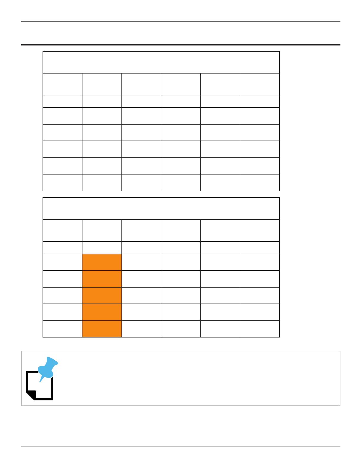
45 AMP: Mild Steel
45 Amp: Mild Steel
Material
Thickness
Cutting
Height
Pierce
Height
Dwell
Time
Cutting
Feed Rate Cutting
(in.) (in.) (in.) (sec) (ipm) AMPs
0.0625 0.06 0.09 0 80 30-34
0.125 0.07 0.1 0 65 32-36
0.1875 0.08 0.11 0 50 35-40
0.25 0.09 0.12 0.25 35 42-45
0.375 0.09 0.12 0.5 25 45
45 Amp: Mild Steel - Fine Cut Consumables
Material
Thickness
Cutting
Height
Pierce
Height
Dwell
Time
Cutting
Feed Rate Cutting
(in.) (in.) (in.) (sec) (ipm) AMPs
0.0625 0.05 0.09 0 80 30-34
0.125 0.06 0.1 0 65 32-36
0.1875 0.07 0.11 0 50 35-40
0.25 0.08 0.12 0.25 35 42-45
0.375 0.08 0.12 0.5 25 45
Re-do the Torch Mount when changing between ne cut consumables and regular
consumables.
Other manuals for Dragon A400
14
Table of contents
Other Bend-Tech Industrial Equipment manuals

Bend-Tech
Bend-Tech Dragon A400 User manual

Bend-Tech
Bend-Tech Dragon mAchines User manual

Bend-Tech
Bend-Tech Dragon A400 Installation and operation manual

Bend-Tech
Bend-Tech Dragon User manual

Bend-Tech
Bend-Tech DRAGON A150 User manual

Bend-Tech
Bend-Tech Dragon A400 User manual

Bend-Tech
Bend-Tech Dragon A400 User manual

Bend-Tech
Bend-Tech Dragon A400 Installation guide

Bend-Tech
Bend-Tech Dragon A400 Installation guide

Bend-Tech
Bend-Tech Dragon mAchines User manual


