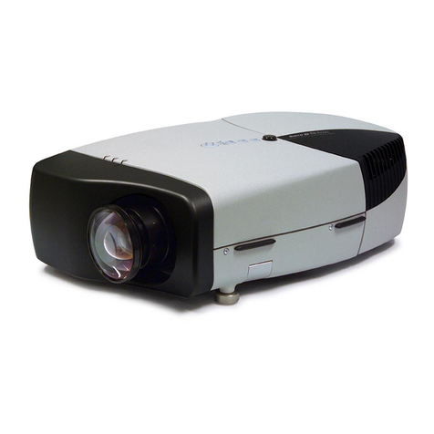
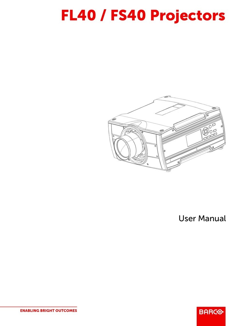
Barco Vision 3200 User manual

BARCO PROJECTION SYSTEMS
INSTALLATION MANUAL
VISION
3200
Art. No. :
R5975428
Date :
290997
R9001180

Federal communication commission (FCC statement)
This equipment has been tested and found to comply with the limits for a class B digital device, pursuant to Part 15 of the FCC ules. These
limits are designed to provide reasonable protection against harmful interference when the equipment is operated in a commercial environment.
This equipment generates, uses, and can radiate radio frequency energy and, if not installed and used in accordance with the instruction
manual, may cause harmful interference to radio communications. Operation of this equipment in a residential area is likely to cause harmful
interference in which case the user will be required to correct the interference at his own expense.
Instructions to the user :
if this equipment does cause interference to radio or television reception, the user may try to correct the interference by one or more of the
following measures :
- e-orientation of the receiving antenna for the radio or television.
- elocate the equipment with respect to the receiver.
- Plug the equipment into a different outlet so that the equipment and receiver are on different branch circuits.
- Fasten cables connectors to the equipment by mounting screws.
Note :
The use of shielded cables is required to comply within the limits of Part15 of FCC rules and EN55022
BARCO nv/Projection Systems
Noordlaan 5
B-8520 Kuurne
Belgium
Tel : +32/56/368211
Fax : +32/56/351651
Visite Barco at the web : http://www.barco.com
Printed in Belgium
Due to constant research, the information in this manual is subject to change without notice.
Produced by BARCO NV, September 1997.
All rights reserved.
Trademarks are the rights of their respective owners.

i-1
Table of Contents
5975428 BA COVISION 3200 290997
iTABLE OF CONTENTS
TABLE OF CONTENTS .............................................................................................................................................................................. i-1
SAFETY INST UCTIONS ......................................................................................................................................................................... 1-1
INSTALLATION MODE ............................................................................................................................................................................. 2-1
Starting up the Installation Mode ................................................................................................................................................... 2-1
Configuration ................................................................................................................................................................................. 2-1
Internal Patterns ............................................................................................................................................................................ 2-1
How to use the built-in adjustable lensholder .............................................................................................................................. 2-2
HA DWA E SET UP ................................................................................................................................................................................ 3-1
Set up of the baud rate for communication with a computer ...................................................................................................... 3-1
Set up of the projector address ................................................................................................................................................... 3-2
How to activate the password function ...................................................................................................................................... 3-2

1-1
Safety Instructions
5975428 BA COVISION 3200 290997
1SAFETY INSTRUCTIONS
Notice on safety
Projectors are built in accordance with the requirements of the
international safety standards EN60950, UL 1950 and CSA C22.2 No.
950, which are the safety standards of information technology
equipment including electrical business equipment.
These safety standards impose important requirements on the use
of safety critical components, materials and isolation, in order to
protect the user or operator against the risk of electric shock and
energy hazard, and having access to live parts.
Safety standards also impose to the internal and external tempera-
ture rises, radiation levels, mechanical stability and strength, enclo-
sure construction and protection against risk of fire.
Simulated single fault condition testing ensures the safety of the
equipment to the user even when the equipment's normal operation
fails.
Installation instructions
Before operating your projector please read this manual thoroughly,
and retain it for future reference
Installation and preliminary adjustments should be performed by
qualified BARCO personnel or authorized BARCO service dealers
OWNERS RECORD
The part number and serial number are located at the front of the
projector. ecord these numbers in the spaces provided below.
efer to them whenever you call upon your BA CO dealer regarding
this product.
PART NUMBER:
SER. NUMBER:
DEALER:
The lightning flash with an arrowhead within a
triangle is intended to tell the user that parts
inside this product are risk of electrical shock
to persons.
The exclamation point within a triangle is in-
tended to tell the user that important operating
and/or servicing instructions are included in the
technical documentation for this equipment.
Warning
To prevent fire or ele tri al sho k hazard, do not expose
this proje tor to rain or moisture
Federal communication commission (FCC statement)
This equipment has been tested and found to comply with the limits
for a class B digital device, pursuant to Part 15 of the FCC ules.
These limits are designed to provide reasonable protection against
harmful interference when the equipment is operated in a commercial
environment. This equipment generates, uses, and can radiate radio
frequency energy and, if not installed and used in accordance with
the instruction manual, may cause harmful interference to radio
communications. Operation of this equipment in a residential area is
likely to cause harmful interference in which case the user will be
required to correct the interference at his own expense.
Instructions to the user :
if this equipment does cause interference to radio or television
reception, the user may try to correct the interference by one or more
of the following measures :
- e-orientation of the receiving antenna for the radio or television.
- elocate the equipment with respect to the receiver.
- Plug the equipment into a different outlet so that the equipment and
receiver are on different branch circuits.
Fasten cables connectors to the equipment by mounting screws.
Note :
The use of shielded cables is required to comply within the limits
of Part15 of FCC rules and EN55022
General safety instructions.
* All the safety and operating instructions should be read before using
this unit.
* The operating instructions manual should be retained for future
reference.
* All warnings on the projector and in the documentation manuals
should be adhered to.
* All instructions for operating and use of this equipment must be
followed precisely.
ON SAFETY
* This product should be operated from an AC power source.
This projector may be connected to an IT-power system.
* This product is equipped with a 3-wire grounding plug, a plug having
a third (grounding) pin. This plug will only fit into a grounding-type
power outlet. This is a safety feature. If you are unable to insert the
plug into the outlet, contact your electrician to replace your
obsolete outlet. Do not defeat the purpose of the grounding-type
plug.
WARNING FOR THE CUSTOMERS: THIS APPA ATUS MUST BE
G OUNDED (EA THED) via the supplied 3 conductor AC power
cable.
(If the supplied power cable is not the correct one, consult your
dealer.)
A. Mains lead (AC Power ord) with CEE 7 plug:
The colors of the mains lead are colored in
accordance with the following code:
Green-and-yellow: Earth (safety earth)
Blue: Neutral
Brown: Live

1-2
Safety Instructions
5975428 BA COVISION 3200 290997
* Do not allow anything to rest on the power cord. Do not locate this
product where persons will walk on the cord.
* To disconnect the cord, pull it out by the plug. Never pull the cord
itself.
* If an extension cord is used with this product, make sure that the
total of the ampere ratings on the products plugged into the
extension cord does not exceed the extension cord ampere rating.
Also make sure that the total of all products plugged into the wall
outlet does not exceed 15 amperes.
* Never push objects of any kind into this product through cabinet slots
as they may touch dangerous voltage points or short out parts that
could result in a risk of fire or electrical shock.
* Never spill liquid of any kind on the product. Should any liquid or solid
object fall into the cabinet, unplug the set and have it checked by
qualified service personnel before resuming operations.
* Lightning - For added protection for this video product during a
lightning storm, or when it is left unattended and unused for long
periods of time, unplug it from the wall outlet. This will prevent
damage to the projector due to lightning and AC power-line surges.
* To reduce the lamp heat of the projector, switch the projector first
to stand-by and let the projector lamp cool down for at least 15
minutes. Then the projector may be switched off with the power
switch.
On Installation
* Do not place this projector on an unstable cart, stand, or table. The
projector may fall, causing serious damage to it.
* Do not use this projector near water.
* Use only the power cord supplied with your projector. While
appearing to be similar, other power cords have not been safety
tested at the factory and may not be used to power the projector.
For a replacement power cord, contact your dealer.
* Slots and openings in the cabinet and the sides are provided for
ventilation; to ensure reliable operation of the projector and to
protect it from overheating, these openings must not be blocked or
covered. The openings should never be blocked by placing the
product on a bed, sofa, rug, or other similar surface. T h i s
prod-uct should never be placed near or over a radiator or heat
register. This projector should not be placed in a built-in
installation or enclosure unless proper ventilation is provided.
* Do not block the projector cooling fans or free air movement under
and around the projector. Loose papers or other objects may not
benearer to the projector than 4" on any side.
On Servicin
Do not attempt to service this projector yourself, as opening or
removing covers may expose you to dangerous voltage potential and
risk of electric shock! efer all projector service to a qualified BA CO
service center.
Call for service in the following conditions :
- When the power cord or plug is damaged or frayed.
- If liquid has been spilled into the projector.
- If the product has been exposed to rain or water.
- If the product does not operate normally when the operating
instructions are followed.
Adjust only those controls that are covered by the operating
in-structions since improper adjustment of the other controls may
result in damage and will often require extensive work by a qualified
technician to restore the product to normal operation;
- If the product has been dropped or the cabinet has been damaged;
- If the product exhibits a distinct change in performance, indicating
a need for service.
Repla ement parts - When replacement parts are required, be
sure the service technician has used original BA CO replacement
parts or authorized replacement parts which have the same char-
acteristics as the BA CO original part. Unauthorized substitutions
may result in degraded performance and reliability, fire, electric shock
or other hazards. Unauthorized substitutions may void warranty.
Safety he k - Upon completion of any service or repairs to this
projector, ask the service technician to perform safety checks to
determine that the projector is in proper operating condition.
The projecor uses a 575 W metal halide projection lamp. eplacing
the projection lamp with any other projection lamp can cause
overheating or unacceptable image quality. Use only the projection
lamps specified by BA CO, or an authorized BA CO dealer or
service center.
On Cleanin
Unplug this product from the wall outlet before cleaning. Do not use
liquid cleaners or aerosol cleaners. Use a damp cloth for cleaning.
To keep the cabinet looking brand-new, periodically clean it with a soft
cloth. Stubborn stains may be removed with a cloth lightly dampened
with mild detergent solution. Never use strong solvents, such as
thinner or benzine, or abrasive cleaners, since these will damage the
cabinet.
To ensure the highest optical performance and resolution, the
projection lenses are specially treated with an anti-reflective coating,
therefore : avoid touching the lens. To remove dust on the lens, use
a soft dry cloth. Do not use a damp cloth, detergent solution, or thinner.
Follow the lens cleaning procedure on Appendix D in the Owners
Manual.
On Repackin
Save the original shipping carton and packing material; they will come
in handy if you ever have to ship your projector. For maximum
protection, repack your set as it was originally packed at the factory.
On illumination
In order to obtain the best quality for the projected image, it is essential
that the ambient light which is allowed to fall on the screen be kept
to an absolute minimum.
When installing the projector and screen, care must be taken to avoid
exposure to ambient light directly on the screen. Avoid adverse
illumination on the screen from direct sunlight or fluorescent lighting
fixtures.
The use of controlled ambient lighting, such as incandescent spot light
or a dimmer, is recommended for proper room illumination. Where
possible, care should also be taken to ensure that the floors and walls
of the room in which the projector is to be installed are non-reflecting,
dark surfaces. Brighter surfaces will tend to reflect and diffuse the
ambient light and hence reduce the contrast of the projected image
on the screen.
B. Power ord with ANSI 73.11 plug:
The wires of the power cord are colored in
accordance with the following code.
Green/yellow: ground
White: neutral
Black: live

1-3
Safety Instructions
5975428 BA COVISION 3200 290997
Remarque sur la Sécurité
Les projecteurs sont fabriqués conformément aux exigences des
normes de sécurité internationales EN60950, UL 1950 et CSA C22.2
No. 950. Ces normes de sécurité sont imposées aux équipements de
la technologie informatique incluant les équipements électriques.
Ces normes de sécurité imposent des exigences importantes sur
lemploi des composantes, des matériaux et de lisolation dont la
sécurité est critique, afin de protéger lutilisateur contre le risque
dune décharge électrique et davoir accès aux parties sous tension.
Les normes de sécurité aussi imposent des limitations concernant la
hausse de la température interne et externe, les niveaux de radiation,
la stabilité et la force mécanique, la construction du cadre métallique
à lintérieure et la protection contre les risques dincendie.
Les épreuves auxquelles léquipement a été subi assurent la sécurité
totale de lutilisateur, même lorsque léquipement ne fonctionne pas
normalement.
Instructions pour linstallation
Lire ce manuel complètement avant de mettre lappareil en fonction-
nement et le conserver pour consultation ultérieure.
Linstallation et les réglages préliminaires devraient être faits par du
personnel qualifié BA CO ou par des agents autorisés du service
BA CO.
DONNÉES POUR LE PROPRIÉTAIRE
Le numéro de pièce et le numéro de série sont situés à lavant du
projecteur. Copier ces numéros dans les espaces prévus ci-dessous.
Se référer à ces numéros chaque fois que vous consultez votre
agent BA CO concernant cet appareil.
NUMERO DE PIECE :
NUMERO DE SERIE :
AGENT :
POUR EVITER DES RISQUES DINCENDIE OU DE CHOCS
ELECTRIQUES, NE PAS EXPOSER CE PROJECTEUR A LA
PLUIE OU A LHUMIDITE
Fédéral communication commission (FCC statement)
Cet équipement a été testé et trouvé conforme aux limites imposées
aux appareils digitaux de classe B, selon la section 15 des règles FCC.
Ces limites sont conçues pour fournir une protection raisonnable
contre les interférences lorsque lutilisation doit se faire dans un
environnement commercial. Cet équipement génère, utilise et peut
émettre de lénergie aux fréquences radio, et sil nest pas installé
et utilisé conformément aux instructions du manuel, il peut créer des
interférences désavantageuses dans les communications radio.
Lutilisation de cet équipement dans des zones résidentielles peut
créer des interférences. Le cas échéant, lutilisateur devra prendre
toutes les mesures requises pour les amoindrir, à ses propres frais.
Instructions pour lutilisateur :
Si cet équipement cause des interférences de radio ou de télévision,
lutilisateur peut essayer de corriger les interférences en appliquant
une ou plusieurs de les mesures suivantes :
- é-orienter lantenne radio ou télévision.
- Déplacer l équipement concernant le récepteur.
- Brancher l appareil sur une autre prise de telle sorte que lappareil
et le récepteur se trouvent sur différents circuits électriques.
. Fixer les connecteurs des câbles a léquipement au moyen des vis.
emarque :
Lutilisation de câbles blindés est exigée afin dobserver les règles
de la section 15 des règles FCC et EN55022
Prescriptions de sécurité énérales.
* Lire toutes les prescriptions de sécurité et de fonctionnement avant
dutiliser cet appareil.
* Le manuel de prescriptions de sécurité et de fonctionnement doit
être conservé pour consultation ultérieure.
* Il faut respecter tous les avertissements mentionnés sur le projec-
teur et dans les manuels.
* Suivre fidèlement toutes les prescriptions dutilisation et de fonction-
nement de cet équipement.
SECURITE
* Cet équipement doit fonctionner sur une source à courant alternatif.
Ce projecteur peut être branché sur un système à IT courant.
* Cet appareil est équipé dun connecteur à trois broches dont une
mise à la terre. Le connecteur nest adapté quà des prises de courant
du type avec terre. Ceci est une mesure de sécurité. Si le connecteur
ne sadapte pas dans la prise, contacter votre électricien pour
remplacer la prise non valable. Ne pas compromettre le but du
connecteur de terre.
Avertissement pour les utilisateurs : CE P OJECTEU DOIT ÊT E MIS
À LA TE E avec le cordon secteur fourni.
(Si le cordon secteur n'est pas correct, consulter votre revendeur.)
A. Cordon dalimentation ave onne teur CEE7
Les couleurs des fils du cordon dalimentation
sont codées comme suit :
Vert et jaune : terre
Bleu : neutre
Brun : sous tension (actif)
B. Cordon dalimentation ave onne teur ANSI 73.11
Les couleurs des fils du cordon dalimentation
sont codées comme suit :
Vert/Jaune : terre
Blanc : neutre
Noir : actif
RISQUE D'ELECTRO-
CUTION NE PAS OUVRIR
ATTENTION
ATTENTION : AFIN DE REDUIRE LE RISQUE DE CHOCS
ELECTRIQUES, NE PAS ENLEVER LE COUVERCLE (OU LE DOS)
IL N'Y A PAS DE PIECES REPARABLES PAR L'UTILISATEUR A
L'INTERIEUR
LE SERVICE NE PEUT ETRE EFFECTUE QUE PAR DU PERSONNEL
QUALIFIÉ
Léclair avec une tête de flèche dans un triangle
indique à lutilisateur que les pièces à lintérieur de
lappareil présentent un risque de chocs électri-
ques.
Le point dexclamation dans un triangle indique à
lutilisateur que des instructions de fonctionne-
ment et/ou de service sont comprises dans la
documentation technique de cet équipement.
AVE TISSEMENT

1-4
Safety Instructions
5975428 BA COVISION 3200 290997
* Ne rien laisser en appui sur le cordon dalimentation. Ne pas placer
ce cordon là où des personnes risques de marcher dessus.
* Pour débrancher le cordon, le tirer par le connecteur, jamais par le
cordon lui-même.
* Si on utilise une rallonge, vérifier que le total des courants des
appareils raccordés à cette rallonge ne dépasse pas la capacité
nominale du câble de rallonge. Vérifier aussi que la somme des
consommations des appareils raccordés à la prise murale ne
dépasse pas 15 ampères.
* Ne jamais introduire un objet quelconque dans lappareil à travers
les fentes du boîtier, car ils pourraient être en contact avec des
points de tension dangereux ou court-circuiter des pièces, ce qui
pourrait entraîner un risque dincendie ou de choc électrique.
* Ne jamais répandre un liquide quelconque sur lappareil. Si un liquide
ou un objet solide tombe dans le boîtier, débrancher lappareil et le
faire vérifier par du personnel qualifié avant de reprendre lutilisa-
tion.
* Foudre - Pour une protection supplémentaire de cet appareil vidéo
lors dun orage ou sil nest pas employé et laissé sans surveillance
pendant de longues périodes, le débrancher de la prise murale. Ceci
évite tout endommagement au projecteur par la foudre ou par des
impulsions sur le secteur.
* Avant de débrancher le projecteur, réduire la chaleur de la lampe
en commutant le projecteur en mode dattente et laisser refroidir la
lampe du projecteur pendant 15 minutes au moins. Puis le projecteur
peut être débranché par linterrupteur secteur.
LInstallation
* Ne pas placer le projecteur sur un chariot, un support ou une table
instable. Le projecteur risquerait de tomber causant des dégâts
sérieux au projecteur.
* Ne pas utiliser le projecteur à proximité deau.
* Nutiliser que le cordon dalimentation fourni avec votre projecteur.
Bien quils se ressemblent, dautres cordons dalimentation nont
pas subi des tests de sécurité dans lusine et pour cette raison ils
ne peuvent pas être utilisés pour actionner le projecteur. Si vous
avez besoin dun cordon dalimentation de remplacement, contactez
votre agent.
* Les fentes et les ouvertures pourvues dans le boîtier et au dos ou
sur le fond, sont destinées à la ventilation. Pour assurer un
fonctionnement fiable du projecteur et le protéger de toute
surchauffe, ses ouvertures ne doivent être ni obstruées ni recou-
vertes. Les ouvertures ne devraient jamais être obstruées en
plaçant lappareil sur un lit, un divan, un tapis ou toute autre surface
similaire. Lappareil ne devrait jamais être placé près ou au-dessus
dun radiateur ou autre source de chaleur. Ce projecteur ne doit pas
être installé dans une installation encastrée ou fermée, sauf si une
ventilation suffisante est assurée.
* Laisser suffisamment despace autour du projecteur et ne pas
obstruer la circulation de lair. Ne pas mettre des feuilles libres ou
dautres objets plus près de 11 cm du projecteur.
Entretien et Réparation
Ne pas essayer de réparer le projecteur vous-même, puisque ouvrir
le boîtier ou lenlèvement des blindages peuvent vous exposer à une
puissance électrique dangereuse et au risque dune décharge
électrique.
Contacter le service technique qualifié dans les cas suivants :
- Si le cordon secteur ou la prise de courant est endommagé ou
effiloché.
- Si on a répandu du liquide dans le projecteur.
- Si lappareil a été exposé à la pluie ou à de leau.
- Si l appareil ne fonctionne pas normalement, bien que les instruc-
tions soient correctement suivies. Ne régler que les commandes
décrites dans les instructions de fonctionnement, car un mauvais
réglage dautres commandes peut entraîner des dégâts et souvent
nécessiter un travail important par un technicien qualifié pour
remettre lappareil en conditions de fonctionnement normal.
- Si lappareil est tombé ou si le boîtier est endommagé.
- Si lappareil présente des changements nets de performance,
indiquant un besoin de réparation.
Piè es de re hange - Lorsquon a besoin des pièces de rechange,
veiller à ce que le technicien de service utilise des pièces dorigine
BA CO ou des pièces équivalentes autorisées qui ont les mêmes
caractéristiques que la pièce dorigine BA CO. Un remplacement par
des pièces de rechange non autorisées peut nuire à la performance
et la fiabilité, entraîner incendies, chocs électriques ou dautres
dangers. Lutilisation de pièces de rechange non autorisées peut
annuler la garantie.
Vérifi ation de sé urité - Lorsquun service ou une réparation sur
ce projecteur est terminé, demander au technicien de service de faire
les vérifications de sécurité pour sassurer que le projecteur est en
bon état de fonctionnement.
Le projecteur emploie une lampe halogène à vapeurs métalliques de
575 W. emplacer la lampe par une lampe de projection quelconque
peut causer la surchauffe ou une qualité de limage inacceptable.
Nutiliser que des lampes de projection indiquées par BA CO ou un
agent autorisé de BA CO ou un service.
Nettoya e
Débrancher lappareil de la prise avant tout nettoyage. Ne pas utiliser
des détergents liquides ou des aérosols. Utiliser un chiffon humide
pour le nettoyage.
Pour garder au boîtier son aspect neuf, le nettoyer régulièrement
avec un chiffon doux. Des tâches tenaces peuvent être enlevées
avec un chiffon humidifié par une solution de détergent doux. Ne
jamais utiliser des solvants forts, tels que du thinner ou du benzène,
ni des produits de nettoyage abrasifs, car ils pourraient endommager
le boîtier.
Pour garantir les meilleures performance et définition, les objectifs de
projection sont spécialement traités avec un revêtement anti-reflets.
En conséquence : éviter de toucher les objectifs. Pour enlever la
poussière de lobjectif, utiliser un chiffon sec et doux. Ne pas utiliser
de chiffon humide, de solution détergente ou de diluant. especter
la méthode de nettoyage des objectifs indiquée dans lannexe D au
manuel d'utilisateur.
Ré-emballa e
Conserver lemballage et les produits demballage dorigine, ils seront
dun précieux secours sil avère utile dexpédier le projecteur. Pour
une protection maximale, ré-emballer lappareil de la même manière
quà lusine.
Eclaira e
Pour garantir la meilleure qualité possible de limage projetée, il est
essentiel que léclairage ambiant incident sur lécran soit réduit au
strict minimum.
Lors de linstallation du projecteur et de lécran, il faut veiller à éviter
toute exposition directe de lécran à la lumière ambiante. Eviter tout
éclairage perturbateur sur lécran par des rayons du soleil ou des
éclairages fluorescents.
Lutilisation dun éclairage ambiant contrôlable, tel quun spot incan-
descent ou un variateur de lumière est recommandée pour obtenir un
éclairage correct de la pièce. Dans la mesure du possible veiller à ce
que les parois et le sol de la pièce dans laquelle le projecteur doit être
installé soient non-réfléchissants et de couleur foncée. Des surfaces
brillantes réfléchissent et diffusent la lumière ambiante et par consé-
quent réduisent le contraste de limage sur lécran.

2-1
Installation Mode
5975428 BARCOVISION 3200 290997
2INSTALLATION MODE
Starting up the Installation Mode
Push the control disk up or down to highlight Installation and then
press ENTER.
ADJUSTMENTMODE
Select a path from below :
RANDOM ACCESS
INSTALLATION
SERVICE
Source 01
INSTALLATION
CONVERGENCE
CONFIGURATION
INTERNALPATTERNS
Select with or
then <ENTER>
<EXIT> to return.
ENTER continues to the Installation mode selection menu.
EXIT returns to operational mode.
The following item can be selected in the Installation mode :
Configuration : to set up the projector position.
Internal Patterns :
- outline
- color bars
- multiburst
- checker board
- purity
- Page Char
- Alpha-numeric Char
Configuration
Highlight "Configuration" by pushing the control disk up or down and
press ENTER to select.
For more information, see Projector configuration in chapter Installa-
tion Set Up.
Select with or
then <ENTER>
<EXIT> to return.
INSTALLATION
CONVERGENCE
CONFIGURATION
INTERNALPATTERNS
INSTALLATION
CONVERGENCE
CONFIGURATION
INTERNALPATTERNS
INTERNALPATTERNS
OUTLINE
COLOR BARS
MULTIBURST
CHECKER BOARD
PURITY
PAGE CHAR
ALPHA-NUMERICCHAR
Select with or
then <ENTER>
<EXIT> to return.
Internal Patterns
Theprojectorisequippedwithdifferentinternalpatternswhichcanbe
used for measurment purposes.
Highlight "Internal Patterns" by pushing the control disk up or down
and press ENTER to display the Internal Pattern selection menu.
The following test pattern are available :
- Outline (not yet available)
- Color Bars
- Multiburst
- Checker Board
- Purity
- Page Char
- Alpha-numeric Char
Each pattern (except Purity) can be inverted by pressing ENTER.
To return to the normal pattern, press EXIT.

2-2
Installation Mode
5975428 BARCOVISION 3200 290997
33 MM
Convergence adjustment of the LCD panels.
Every LCD panel has 6 adjustment screws. By turning these screws
you change the relative position of the panels and converge the
image.
Always start with the adjustment of the green panel. When the green
image is correctly focused, it will later on be used as the reference
image to converge the red and blue image.
Next alignments have to be done :
You have to adjust the green panel until the indicated lines on the
screen are focused (sharp lines). Continue with the blue panel and
adjust until the blue lines coincide with the green lines. Than continue
with the red panel until the red lines coincide with the green lines.
Follow the next procedure to adjust the LCD panels.
* Open the top cover as described in Gaining access to the DIP
switches under Connecting to a computer in chapter Connections.
The three mounting parts for the LCD's (two are shown on the drawing
below) are located on the black metal cover. The screws are
indicated from 1 to 6 for each color.
To adjust the convergence, there are test patterns provided in the
service menu.
Push the control stick forward or backward to hightlight Convergence
and press ENTER to display the Convergence menu.
Start with the Green test pattern and continue with the Blue on green
and finish with the ed on green.
INSTALLATION
CONVERGENCE
CONFIGURATION
INTERNALPATTERNS
The pattern shows lines of one pixel.
Near six lines on the displayed pattern, a screw is drawn with a
number next to it (e.g. if displayed in green = corresponding with the
screws and numbers on the green LCD panel).
When turning a screw in the direction marked by the arrow above the
displayed screw on the screen, the line on the screen moves in the
direction of the straight arrow.
Select with or
then <ENTER>
<EXIT> to return.
CONVERGENCE
GREEN
BLUE ON GREEN
RED ON GREEN
HATCH

2-3
Installation Mode
5975428 BARCOVISION 3200 290997
Green focusing
a. Insure all convergence screws are adjusted to a length of about 33
mm (1.3") between the two plates.
b. Adjust the projection lens until optimal focus for point 1 is obtained.
c. Turn screw 2 for optimal focus of the corresponding green line 2
on the screen.
d. This alignment influences the other, so repeat if necessary steps
b. and c. until points 1 and 2 are focused.
e. Turn screw 3 for optimal focus of the corresponding green line 3 on
the screen.
f. epeat if necessary the steps b. to e. until the complet screen is
focused.
g. Secure the projection lens by turning the fastener ring clockwise.
Green position
a. If necessary turn screw 5 until the two horizontal lines 5 on the
screen are on one horizontal line.
When the green pattern is correctly focused, press EXIT to return to
the Test pattern menu.
Blue on green onvergen e.
Push the control disk up or down to hightlight Blue on green and press
ENTER to display the Blue on green test pattern.
The longest lines are the blue lines. These lines must be converged
with the green lines.
The drawn screws and numbers are displayed in blue.
Follow next steps :
Blue focusing
a. Insure all convergence screws are adjusted to a length of about 33
mm (1.3") between the two plates.
b. Turn screw 1 for optimal focus of the corresponding point 1 on the
screen.
c. Turn screw 2 for optimal focus of the corresponding point 2 on the
screen.
d. Due to interaction, it may be necessary to repeat step b. and c. until
point 1 and 2 are focused.
e. Turn screw 3 for optimal focus of the corresponding point 3 on the
screen.
f. Due to interaction, it may be necessary to repeat steps b. to d. until
point 1, 2 and 3 are correctly focused.
Select with or
then <ENTER>
<EXIT> to return.
CONVERGENCE
GREEN
BLUE ON GREEN
RED ON GREEN
HATCH
Blue position
g. Turn screw 4 until the red horizontal line coincide with the green
horizontal line in point 4 on the screen.
h. Turn screw 5 until both horizontal lines marked with 5 are on one
horizontal line.
i. epeat step g. and h. until the horizontal lines are converged.
j. Adjust screw 6 for optimal convergence of the vertical lines.
k. epeat step i. and j. until a optimal convergence in horizontal and
vertical direction is obtained.

2-4
Installation Mode
5975428 BARCOVISION 3200 290997
l. Due to interaction, turning on screw 4, 5 and 6 can influence the
focus of the image. If necessary, repeat procedure from step b. .
Red on green onvergen e.
Push the control disk up or down to highlight Red on green and press
ENTER to display the ed on green test pattern.
epeat the same procedure as for Blue on green lines but read red
when blue is indicated.
To check the result of the convergence adjustments, highlight Hatch
and press ENTER. A hatch pattern will be displayed on the screen.
ENTER : displays a hatch pattern.
EXIT : returns to the service menu.
All lines must be displayed in white, if not so repeat the convergence
adjustment procedure.
How to use the built in adjustable lensholder.
With the lensholder, it is possible to shift the displayed image up or
down on the screen without moving the projector from its normal
positioin and without any geometric picture distortion. This built-in
featureisparticularlyusefulforuseindual projector configurations or
for applications when the projector cannot be installed in its standard
position.
Features :
- Vertical and horizontal shift of the lens without removing the top
cover,
5 mm left and 5 mm right
15 mm up and 15 mm down.
- Makes it possible to project a geometric non-distored image from a
non-standard position.
-The shiftofthelensholder isnotdetermined by thelensbut depends
on the screen width.
- Can be used with all available lenses.
Lens shift up/down
Lens shift left/right
Select with or
then <ENTER>
<EXIT> to return.
CONVERGENCE
GREEN
BLUE ON GREEN
RED ON GREEN
HATCH
Select with or
then <ENTER>
<EXIT> to return.
CONVERGENCE
GREEN
BLUE ON GREEN
RED ON GREEN
HATCH

2-5
Installation Mode
5975428 BARCOVISION 3200 290997
-0,5
-0,25
0
0,25
0,5
123456
80 120 160 200 240
40 30
15
-1,5
-1
-0,5
0
0,5
1
1,5
123456
80 120 160 200 240
40 90
60
30
Screen Width
Horizontal Screen Shift
0
-15
-30
Maximum 5 mm right lens shift
Maximum 5 mm left lens shift
0
-30
-60
-90
Screen Width
Vertical Screen Shift
Maximum 15 mm downwards lens shift
Maximum 15 mm upwards lens shift
no shift
5 mm
10 mm
-5 mm
-10 mm
2.5 mm
no shift
-2.5 mm
How to shift the image :
- First shift the image left or right until the correct horizontal position
isobtained. Turnclockwisetoshifttheimagetotheright,turncounter
clockwise to shift to the left. Use the hand screw.
- Shift the image up or down until the correct vertical position of the
image is obtained. Turn clockwise to shift the image up, turn counter
clockwise to shift down. Use the hand screw.
Midposition of the adjustable lensholder.
-Ifthetopcoverisopened,thelensholder indication line has to match
with the center of the hole in the plate behind the lensholder.
-Ifthe top cover is closed, the3indication lines on the lensholderhas
to match with indication on the top cover.
hole
indication
line
Horizontal shift is function of the Screen Width for
various lens shifts.
Vertical shift is function of the Screen Width for various lens shifts.
Both the vertical and horizontal shift of the displayed picture can be
calculated as follows :
Screen shift = lens shift x 1 + (Screen width / LCD panel width)
LCD panel width for 3200 series : 0,06480 m (2.551 inch)

3-1
Hardware Set Up
5975428 BA COVISION 3200 290997
3
Set up of the baud rate for communication with a computer.
S1
S2
2
13
On
Off
HARDWARE SET UP
The communication speed between projector and computer, e.g. PC
or MAC, has 8 possible speeds. With DIP switches S2(1,2,3) on the
controller unit, it is possible to select the baud rate (communication
speed).
Gaining access to the DIP switches
Power down the projector and unplug the power cord from the wall
outlet.
Turn both lock screws with a screwdriver or coin counter
clockwise.
Lift up and pivot the top cover. Attention : the cover is not secured
with an incorporated support. When opening, turn it over slowly.
The processor module with the DIP switches is located on the front
side.
Loosen the locking
screws.
Open the top cover
Baud rate setting
Change the position of the DIP switches with a small
screwdriver.
If all switches are in the correct position, close the top
cover and secure it by turning the lock screw clockwise.
Connect the power cord to the wall outlet and switch
on the projector.
baud rate S2/1 S2/2 S2/3
9600 OFF OFF OFF
4800 ON OFF OFF
2400 OFF ON OFF
1200 ON ON OFF
600 OFF OFF ON
300 ON OFF ON
150 OFF ON ON
75 ON ON ON
BAUD RATE SWITCHES

3-2
Hardware Set Up
5975428 BA COVISION 3200 290997
S1
S2
1
On
Off
How to activate the password function?
S1
S2
on
off
When DIP switch 4 (S2) is in the :
- ON position, password is activated.
-OFF position, password not activated, service mode
is free accessible.
The password function can be hardware set with a DIP switch on
the CPU module. To change the position of this DIP switch, it is
necessary to open first the top cover.
How to ontrol the proje tor or proje tors.
The projector's address may be set to any value between 0 and 255.
When the address is set, the projector can be controlled now :
- CU for addresses between 0 and 9.
- computer, e.g. IBM PC (or compatible), Apple MAC, etc. for
addresses between 0 and 255.
Note : a projector will respond to a CU set to an address of '0'
regardless of what address is set in the projector itself.
Password
switch value
11
22
34
48
516
632
764
8 128
Example : address 83
DIP switch 1 2 3 4 5 6 7 8
setting 1 1 0 0 1 0 1 0
Summary : 1x1 + 1x2 + 0x4+ 0x8+ 1x16 + 0x32 + 1x64 + 0x128 = 83
Every projector requires an individual address between 0 and 255
which is set with hardware DIP switches. To change that address,
it is necessary to first open the top cover (see 'Set up of the baud
rate for communication with a computer' under this chapter.).
8 DIP switches (S1) are provided on the CPU module. Each DIP switch
has its own decimal value (ON='1', OFF = '0'). The summary of the
values associated to those DIP switches gives the address
Set up of the projector address.
Projector address
Table of contents
Other Barco Projector manuals

Barco
Barco PFWX-51B User guide

Barco
Barco Thor Series User manual

Barco
Barco BARCODATA 2100 User manual

Barco
Barco BarcoData 3300 User manual

Barco
Barco F50 User manual

Barco
Barco BarcoRLM G5 User manual

Barco
Barco SP2K-S User manual

Barco
Barco DATA 2100 R9001070 User manual

Barco
Barco CTHD-61B User manual

Barco
Barco DP2K-20CLP User guide

Barco
Barco FLM R20+ Performer User manual

Barco
Barco CNWU-61B User manual

Barco
Barco HDF W22 User manual

Barco
Barco R9698236 User manual

Barco
Barco R9001440 User manual

Barco
Barco F22 Series User manual

Barco
Barco CR series User manual

Barco
Barco ACTAS 2 User manual

Barco
Barco RLM-W12 User manual

Barco
Barco HDF W series Technical specifications