Barco R9828960 User manual

BARCO PROJECTION SYSTEMS
BARCO TWIN Interface
R9828960
R9828969
Date : 15122000 Rev : 02 Art. No. : R597612

Due to constant research, the information in this manual is subject to change without notice.
Produced by BARCO N , Dec. 2000.
All rights reserved.
* IBM is a trademark of International Business Machine Incorporated
Trademarks are the rights of their respective owners.
BARCO n.v./Projection Systems
Noordlaan 5
B-8520 Kuurne
Belgium
Tel : +32/56/368211
Fa : +32/56/351651
Visit Barco at the web : http://www.barco.com
Federal communication commission (FCC statement
This equipment has been tested and found to comply with the limits for a class B digital device,
pursuant to Part 15 of the FCC Rules and EN55022. These limits are designed to provide reasonable
protection against harmful interference when the equipment is operated in a commercial environment.
This equipment generates, uses, and can radiate radio frequency energy and, if not installed and
used in accordance with the instruction manual, may cause harmful interference to radio commu-
nications. Operation of this equipment in a residential area is likely to cause harmful interference
in which case the user will be required to correct the interference at his own expense.
Instructions to the user :
If this equipment does cause interference to radio or television reception, the user may try to correct
the interference by one or more of the following measures :
- re-orientation of the receiving antenna for the radio or television.
- relocate the equipment with respect to the receiver.
- plug the equipment into a different outlet so that the equipment and receiver are on different
branch circuits.
- fasten cables connectors to the equipment by mounting screws.
Note : The use of shielded cables is required to comply within the limits of Part15 of FCC
rules and EN550 .

Table of Contents
R597612 BARCO TWIN INTERFACE ____________________________________________________ i-1
SAFETY INSTRUCTIONS ----------------------------------------------------------------------------------------------- 1-1
On safety --------------------------------------------------------------------------------------------------------------- 1-2
On installation -------------------------------------------------------------------------------------------------------- 1-3
On servicing ----------------------------------------------------------------------------------------------------------- 1-4
On cleaning ----------------------------------------------------------------------------------------------------------- 1-4
On repacking---------------------------------------------------------------------------------------------------------- 1-4
DESCRIPTIONS & CONNECTIONS -------------------------------------------------------------------------------- -1
Application Global --------------------------------------------------------------------------------------------------- 2-1
Specifications Twin Interface ------------------------------------------------------------------------------------ 2-1
Front Side of the Interface --------------------------------------------------------------------------------------- 2-2
Back Side of the Interface --------------------------------------------------------------------------------------- 2-3
Computer Interface application drawing --------------------------------------------------------------------- 2-4
Power Connection --------------------------------------------------------------------------------------------------- 2-4
Interconnection Interface / Computer ------------------------------------------------------------------------- 2-4
Interconnection Interface output / display device -------------------------------------------------------- 2-5
ID Bit Combinations ------------------------------------------------------------------------------------------------ 2-6
TABLE OF CONTENTS
i


Safety Instructions
R597612 BARCO TWIN INTERFACE ____________________________________________________ 1-1
Notice on Safety
This equipment is built in accordance with the requirements of the international safety standards
EN60950, UL 1950 and CSA C22.2 No.950, which are the safety standards of information technol-
ogy equipment including electrical business equipment.
These safety standards impose important requirements on the use of safety critical components,
materials and isolation, in order to protect the user or operator against risk of electric shock and
energy hazard, and having access to live parts.
Safety standards also impose limits to the internal and external temperature rises, radiation levels,
mechanical stability and strength, enclosure construction and protection against the risk of fire.
Simulated single fault condition testing ensures the safety of the equipment to the user even when
the equipment's normal operation fails.
INSTALLATION INSTRUCTIONS
Before operating this equipment please read this manual thoroughly, and retain it for future
reference. Installation and preliminary adjustments should be performed by qualified BARCO
personnel or by authorized BARCO service dealers.
OWNERS RECORD
The part number and serial number are located at the bottom side of the interface. Record these
numbers in the spaces provided below. Refer to them whenever you call upon your BARCO dealer
regarding this product.
PART NUMBER :
SR. NUMBER :
DEALER :
SAFETY INSTRUCTIONS
1
WARNING
TO PREVENT FIRE OR ELECTRICAL SHOCK HAZARD, DO NOT
EXPOSE THIS EQUIPMENT TO RAIN OR MOISTURE

Safety Instructions
1-2 ____________________________________________________ R597612 BARCO TWIN INTERFACE
FEDERAL COMMUNICATION COMMISSION (FCC STATEMENT)
This equipment has been tested and found to comply with the limits of a class B digital device,
pursuant to Part 15 of the FCC Rules and EN55022.
These limits are designed to provide reasonable protection against harmful interference when the
equipment is operated in a residential environment. This equipment generates, uses and can
radiate radio frequency energy and, if not installed and used in accordance with the instruction
manual, may cause harmful interference to radio communications. However, there is no guarantee
that interference will not occur in a particular installation. If this equipment does cause harmful
interference to radio or television reception, which can be determined by turning the equipment off
and on, the user is encouraged to try to correct the interference by one or more of the following
measures :
- Reorient or relocate the receiving antenna.
- Increase the separation between the equipment and receiver.
- Connect the equipment into an outlet on a circuit different from that to which the receiver is
connected.
- Consult the dealer or an experienced radio/T technician for help.
Note : The use of shielded cables is required to comply within the limits of Part 15 of FCC
rules and EN550 .
µ All the safety and operating instructions should be read before using this unit.
µ The safety and operating instructions manual should be retained for future reference.
µ All warnings on the equipment and in the documentation manuals should be adhered to.
µ All instructions for operating and use of this equipment must be followed precisely.
On safety
1. This product should be operated from an AC power source.
This interface may be connected to an IT-power system.
POWER REQUIREMENTS
Power requirements for electrical equipment differ from area to area. This instrument adjusts itself for any
input voltage between 85 AC and 245 AC automatically.
. This product is equipped with a 3-wire grounding plug, a plug having a third (grounding) pin.
This plug will only fit into a grounding-type power outlet. This is a safety feature. If you are
unable to insert the plug into the outlet, contact your electrician to replace your obsolete outlet.
Do not defeat the purpose of the grounding-type plug.
WARNING FOR THE CUSTOMER: THIS APPARATUS MUST BE GROUNDED (EARTHED) via
the supplied 3 conductor AC power cable. (If the supplied power cable is not the correct one,
consult your dealer.)
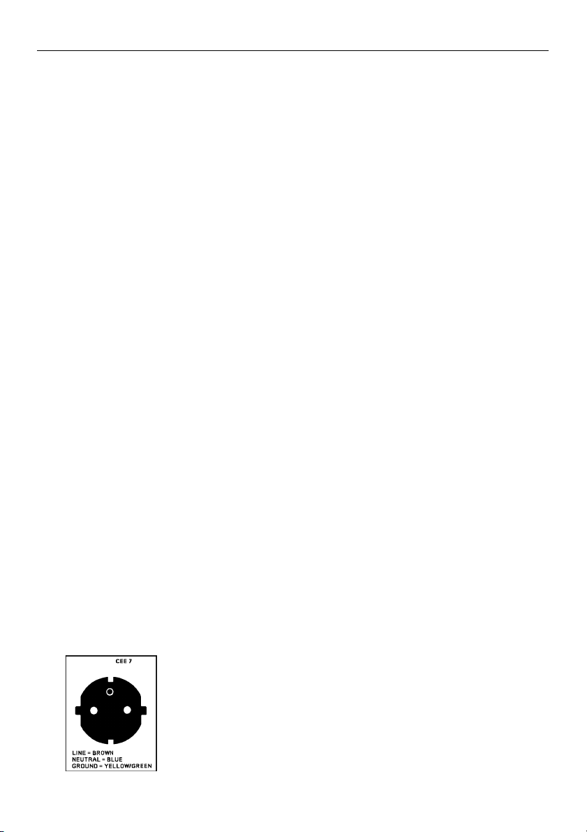
If the Power cord of the Interface is equipped with a CEE 7 PLUG,
A. Mains lead (Power cord) with CEE 7 plug :
The wires of the mains lead are colored in accordance with the following
code.
Green & Yellow : Earth (safety earth)
Blue : Neutral
Brown : Line (live)

Safety Instructions
R597612 BARCO TWIN INTERFACE ____________________________________________________ 1-3
If the Power cord of the Interface is equipped with a ANSI 73.11 PLUG,
B. Power cord with ANSI 73.11 plug :
The wires of the power cord are colored in accordance with the following code.
Green / Yellow : Ground
White : Neutral
Black : Line (live)
3. Do not allow anything to rest on the power cord. Do not locate this product where persons
will walk on the cord.
To disconnect the cord, pull it out by the plug. Never pull the cord itself.
4. If an extension cord is used with this product, make sure that the total of the ampere ratings
on the products plugged into the extension cord does not exceed the extension cord ampere
rating. Also make sure that the total of all products plugged into the wall outlet does not
exceed 15 amperes.
5. Never push objects of any kind into this product through cabinet slots as they may touch
dangerous voltage points or short out parts that could result in a risk of fire or electrical shock.
Never spill liquid of any kind on the product. Should any liquid or solid object fall into the
cabinet, unplug the set and have it checked by qualified service personnel before resuming
operations.
6. Lightning - For added protection for this video product during a lightning storm, or when it is
left unattended and unused for long periods of time, unplug it from the wall outlet. This will
prevent damage to the projector due to lightning and AC power-line surges.
If in doubt, consult a QUALIFIED TECHNICIAN for voltage conversion.
On installation
1. Do not use this equipment near water.
. Slots and openings in the cabinet and the back or bottom are provided for ventilation; to
ensure reliable operation of the product and to protect it from overheating, these openings
must not be blocked or covered. The openings should never be blocked by placing the product
on a bed, sofa, rug, or other similar surface. This product should never be placed near or
over a radiator or heat register.

Safety Instructions
1-4 ____________________________________________________ R597612 BARCO TWIN INTERFACE
On servicing
Do not attempt to service this product yourself, as opening or removing covers may expose you to
dangerous voltage potential and risk of electric shock!
Refer all servicing to qualified service personnel.
Unplug this product from the wall outlet and refer servicing to qualified service personnel
under the following conditions :
a. If liquid has been spilled into the equipment.
b. If the product has been exposed to rain or water.
c. If the product does not operate normally when the operating instructions are followed.
d. If the product has been dropped or the cabinet has been damaged.
e. If the product exhibits a distinct change in performance, indicating a need for service.
Note : Adjust only those controls that are covered by the operating instructions since im-
proper adjustment of the other controls may result in damage and will often require extensive
work by a qualified technician to restore the product to normal operation.
Replacement parts - When replacement parts are required, be sure the service technician has
used original BARCO replacement parts or authorized replacement parts
which have the same characteristics as the BARCO original part. Un-
authorized substitutions may result in degraded performance and reliabil-
ity, fire, electric shock or other hazards. Unauthorized substitutions may
void warranty.
Safety check - Upon completion of any service or repairs to this TWIN INTERFACE, ask the
service technician to perform safety checks to determine that the product
is in proper operating condition.
On cleaning
Unplug this product from the wall outlet before cleaning. Do not use liquid cleaners or
aerosol cleaners. Use a damp cloth for cleaning.
-To keep the cabinet looking brand-new, periodically clean it with a soft cloth. Stubborn stains
may be removed with a cloth lightly dampened with mild detergent solution. Never use strong
solvents, such as thinner or benzine, or abrasive cleaners, since these will damage the
cabinet.
On repacking
Save the original shipping carton and packing material; they will come in handy if you ever have to
ship your equipment. For maximum protection, repack your set as it was originally packed at the
factory.

Descriptions & Connections
R597612 BARCO TWIN INTERFACE ____________________________________________________ 2-1
APPLICATION GLOBAL
Purpose of this interface is to take RGB signals from a computer and to display them on a large screen
projector, while keeping the image on the monitor intact.
As IBM and Apple computers need monitor identification for soft and hardware configuration purposes,
emulation of these identification bits is provided in case no monitor is connected.
In case a monitor is connected, the identification bits of the monitor are fed to the computer.
To obtain the best performing images on the large screen-projecting device, active loop-trough is used
for the monitor output.
RGB signals from the computer are automatically terminated to 75 Ohm, while sync signals, which are
TTL signals are terminated with a 22K pull-up resistor.
SPECIFICATIONS TWIN INTERFACE:
Measured bandwidth : >300MHz @ -3dB.
Rise and fall time better than 1.42 ns
Gain fixed to 1. (Output = Input)
Input : R,G,B, :0.7 pp (no sync) or 1 pp With sync @ 75 Ohm
Sync : TTL level
Output signals :
Loop trough output on DD15 connector:
R, G, B: 0.7 pp (no sync) or 1 pp @ 75 Ohm
Horizontal Sync: TTL
ertical Sync: TTL
Composite Sync: TTL
Output to projector on 5 BNC connectors:
R,G,B: 0.7 pp (no sync) or 1 pp @ 75 Ohm
Horizontal Sync: 1.54 tt
ertical Sync: 1.54 tt
Composite Sync: 1.54 tt
Power supply: Auto ranging Power Supply 87-240 AC 50/60Hz
DESCRIPTIONS & CONNECTIONS
2

Descriptions & Connections
2-2 ____________________________________________________ R597612 BARCO TWIN INTERFACE
T I
WIN NTERFACE
ID BIT SELECTION
On
POWER ID ENABLED
INPUT SYNC
Hor. Vert. Comp.
TO COMPUTER
IBM 640 x 480
APPLE 512 x 384
IBM 800 x 600
APPLE 640 x 480
IBM 1024 x 768
APPLE 640 x 870
IBM 1024 x 768
APPLE 800 x 600
640 x 480 IBM
512 x 384 APPLE
1600 x 1200 IBM
1024 x 768 APPLE
1600 x 1280 IBM
1152 x 870 APPLE
FRONT SIDE OF THE INTERFACE:
- DD15 input connector, labeled TO COMPUTER
With the provided DD15/DD15 cable any GA type Computer can be connected.
With an optional cable Apple Mac computers can be connected to the interface.
- 3 LEDs indicating the sync signals received from the computer. For GA (S GA, XGA) type
computers the H and led should light up. For Mac Computers composite might also, or only light up.
- ID bit selector.
This switch allows emulating a typical IBM or MAC Monitor. IBM and MAC computers need to know which
type of monitor is connected. In case no monitor ID bits are detected, no image is sent to the RGB
outputs resulting in no image on your projector.
In case Monitor identification is present, the software limits the selection options for output resolution.
This results in a safety situation for the monitor. The image will always be in its lock range, and will
always be readable.
When a monitor is connected to the interface, the monitor ID bits are sent to the computer. In this case
the rotary switch is disabled, and the green LED ID enabled will stop glowing.
- Power indicator.
When the mains is connected this LED will indicate the power supply of the unit is up and running.

Descriptions & Connections
R597612 BARCO TWIN INTERFACE ____________________________________________________ 2-3
BACK SIDE OF THE INTERFACE:
-DD15 output connector, labeled MONITOR OUT
The Monitor that was originally connected to your computer can be connected here for local monitoring
the images you want to be projected on your screen.
With an optional cable your Apple Mac Monitor can be connected to the interface.
-5 BNC connectors. These are the connection to the projector. R,G,B signals have standard levels
and should be terminated 75Ω.
The Hor/Comp OUT BNC is outputting composite sync when no 75Ω is connected to the ert.
OUT BNC. If there is a 75Ω load on the ert. OUT; then a Horizontal sync signal is available
on this output.
The ert. output is providing ertical sync signals and should be terminated 75 Ohm if used.
-Two green LEDs indicating signal presence at the sync outputs are available.
Red
OUT MONITOR
OUT
MAINS
100-240V
0.12A 50/60Hz
Vert. H/Cs
Green
OUT Blue
OUT Hor/Comp
OUT Vert.
OUT

Descriptions & Connections
2-4 ____________________________________________________ R597612 BARCO TWIN INTERFACE
Interconnection Interface / Computer
ID BIT SELECTION
IBM 640 x 480
APPLE 512 x 384
IBM 800 x 600
APPLE 640 x 480
IBM 1024 x 768
APPLE 640 x 870
IBM 1024 x 768
APPLE 800 x 600
640 x 480 IBM
512 x 384 APPLE
1600 x 1200 IBM
1024 x 768 APPLE
1600 x 1280 IBM
1152 x 870 APPLE
COMPUTER INTERFACE APPLICATION DRAWING
Power connection
Power Indication
Lamp
to wall outlet
BARCO delivered cable
Monitor
Interface cable
If the interconnection monitor /
interface is not made, install if
necessary the correct identifica-
tion code (ID bit) with the
switches.
T I
WIN NTERFACE
ID BIT SELECTION
On
POWER ID ENABLED
INPUT SYNC
Hor. Vert. Comp.
TO COMPUTER
IBM 640 x 480
APPLE 512 x 384
IBM 800 x 600
APPLE 640 x 480
IBM 1024 x 768
APPLE 640 x 870
IBM 1024 x 768
APPLE 800 x 600
640 x 480 IBM
512 x 3 84 APPL E
1600 x 1200 IBM
1024 x 768 APPLE
1600 x 1280 IBM
1152 x 870 APPLE
to interface power socket
Indication lamp : Indicates
if ID bit selection button is
active or not.
If no monitor is available :
The lamp lights up.
Red
OUT MONITOR
OUT
MAINS
100-240V
0.12A 50/60Hz
Vert. H/Cs
Green
OUT Blue
OUT Hor/Comp
OUT Vert.
OUT

Descriptions & Connections
R597612 BARCO TWIN INTERFACE ____________________________________________________ 2-5
Interconnection Interface output/display device
Red
OUT MONITOR
OUT
MAINS
100-240V
0.12A 50/60Hz
Vert. H/Cs
Green
OUT Blue
OUT Hor/Comp
OUT Vert.
OUT

Descriptions & Connections
2-6 ____________________________________________________ R597612 BARCO TWIN INTERFACE
ID Bits and combinations
In order to make the selection of the ID bits user friendly an 8 position rotary switch is used to select the
most found ID bit combinations in the field.
ID Enabled LED is glowing when the ID bit codes from the rotary switch is active.
ID Bits for IBM Computers
ID Bits for MAC Computers
640 x 480
800 x 600
1024 x 768
1024 x 768i
1280 x 1024
1600 x 1200
1600 x 1280
512 x 384 12 RGB
640 x 480 12, 13, 14
640 x 870 Portrait
800 x 600 S GA
832 x 624 16 color
1024 x 768 19 color
1152 x 870 21 color
This manual suits for next models
1
Table of contents
Other Barco Recording Equipment manuals
Popular Recording Equipment manuals by other brands

Yamaha
Yamaha CRW4416S - CRW - CD-RW Drive user guide

Pioneer
Pioneer PDR-W839 operating instructions

TREBING + HIMSTEDT
TREBING + HIMSTEDT SPI 3 manual

Isotonik Studios
Isotonik Studios Percolator Getting started guide

Aventics
Aventics LP04 operating instructions

ADLINK Technology
ADLINK Technology LPCI-3488A Series user manual