Bardac E3 Series User manual

Quick Start Guide
AC Variable Speed Drive
IP66 (NEMA 4X)
0.37kW – 22kW / 0.5HP – 30HP
110V - 480V 3 Phase input

1
CHECK: Check the correct drive type, check suitable
motor type & info
2
PREPARE: Correct tools, suitable mounting location,
weather protection
3MOUNT: Mechanical mounting
4CONNECT: Power & Control connections
5CHECK: Final check of everything before operation
6POWER ON
7COMMISSION the drive parameters
8OPERATE and check everything is as intended
WARNING! The drive should ONLY be installed by a qualified electrician.
WARNING! In a residential environment, this product may cause radio
interference in which case supplementary mitigation measures may be required.
NOTE This guide does not provide detailed installation, safety or operational instructions.
See the E3 IP66 Outdoor User Manual for complete information.
Unpack and check the drive. Notify the supplier and shipper immediately of any damage.
1CHECK
Identifying the Drive by Model Number
Each drive can be identified by its model number, as shown in the table below.
E-3-1 2 0021 -1 F 1 B
Product Family IP Rating
IP66
FWD/REV
Pot Disconnect
A
B
C
Generation Dynamic Brake Transistor 1 = Not Fitted
4 = Internal Transistor
Frame Size Filter Type 0 = No Filter
F = Internal EMC Filter
Input Voltage 1 = 110 – 115
2 = 200 – 240
4 = 380 – 480
No. Of Input Phases
Output Current x 10
2PREPARE
Prepare the Mounting Location
The drive must be mounted in a vertical position only.
Installation should be on a suitable flat, flame resistant
surface. Do not mount flammable material close to the drive.
Refer to Technical Data and ensure the chosen mounting
location is within the drive specification.
The mounting location should be free from vibration.
Do not mount the drive in any area with excessive humidity,
corrosive airborne chemicals or potentially dangerous dust
particles.
Avoid mounting close to high heat sources.
The drive must not be mounted in direct sunlight. If
necessary, install a suitable shade cover.
The mounting location must be free from frost.
Do not restrict the flow of air through the drive heatsink.
The drive generates heat which must be naturally allowed
to dissipate. Correct air clearance around the drive must
be observed.
If the location is subject to wide ambient temperature
and air pressure variation, install a suitable pressure
compensation valve in the drive gland plate.
NOTE If the drive has been in storage for a period longer than 2 years, the DC link capacitors must be reformed. Refer to
online documentation for further information.
Please scan the QR code
to access the complete
User Manual
or go to www.bardac.com

3MOUNT
Mechanical Dimensions
C
Dimensions
Drive
Size
A B C D E Weight
mm in mm in mm in mm in mm in kg Ib
1232 9 .13 161 6.34 162 6.37 18 9 7.44 148.5 5.85 2.3 5
2257 10 .12 18 8 7. 4 18 6 7. 3 2 200 7. 87 176 6.93 3.5 7. 7
3310 12.2 211 8.3 235 9.25 251. 5 9.9 19 7. 5 7. 78 6.6 14.5
4 360 14 .17 240 9.44 271 10.67 300 11.08 226 8.89 9.5 20.9
Mounting Clearance
Drive Size X Above & Below Y Either Side
mm in mm in
All Frame Sizes 200 7. 87 10 0.39
NOTE
Typical drive heat losses are approximately 3% of operating load conditions.
Above are guidelines only and the operating ambient temperature of the drive MUST be
maintained below the maximum limit at all times.
Mounting Bolts & Tightening Torques
Mounting Bolts Tightening Torques
Frame Size Frame Size
Control Terminals
Power Terminals
All Frame Sizes 4 x M4 (#8) 1, 2, 3 0.5 Nm (4.4 lb-in) 0.8 Nm (7 lb-in)
4 0.5 Nm (4.4 lb-in) 2 Nm (19 lb-in)

4CONNECT
Cable Selection
For 1 phase supply (Sizes 1-3 only), the mains power cables should be connected to L1/L, L2/N.
For 3 phase supplies, the mains power cables should be connected to L1, L2, and L3. Phase sequence is not important.
For compliance with CE and C Tick EMC requirements, refer to online documentation.
A fixed installation is required according to IEC61800-5-1 with a suitable disconnecting device installed between the drive
and the AC Power Source. The disconnecting device must conform to the local safety code / regulations (e.g. within Europe,
EN60204-1, Safety of machinery).
The cables should be dimensioned according to any local codes or regulations. Maximum dimensions are given in the
Rating Tables section of this Quick Start Guide.
Install the Power Wiring
Single phase supply 3 phase supply
L1 L3 EMCL2/N UVW
1 2 3 4 5 6 7 8 9
10
11
I0I0I I0I0I
L1 L3 EMCL2/N UVW
1 2 3 4 5 6 7 8 9
10
11
I0I0I I0I0I
Drive Size Power & Motor Cables
Hole Size Recommended PG Gland Alternative Metric Gland
Size 1 22 PG16 M20
Size 2 & 3 27 PG21 M25
Size 4 37 PG29 -
Motor Terminal Box
Connections
Most general purpose motors
are wound for operation on dual
voltage supplies. This is indicated
on the nameplate of the motor. This
operational voltage is normally
selected when installing the motor
by selecting either STAR or DELTA
connection. STAR always gives the
higher of the two voltage ratings.
Incoming Supply
Voltage
Motor Nameplate
Voltages Connection
230 230 / 400
Delta
400 400 / 690
400 230 / 400 Star

Information for UL Compliance
The E3 drive is designed to meet the UL requirements. For an up to date list of UL compliant products, please refer to UL listing
NMMS.E226333. In order to ensure full compliance, the following must be fully observed.
Input Power Supply Requirements
Supply Voltage 200 – 240 RMS Volts for 230 Volt rated units, + /- 10% variation allowed. 240 Volt RMS Maximum.
380 – 480 Volts for 400 Volt rated units, + / - 10% variation allowed, Maximum 500 Volts RMS.
Frequency 50 – 60Hz + / - 5% Variation
Short Circuit
Capacity
All drives are suitable for use on a circuit capable of delivering not more than 100kA maximum short-circuit Amperes
symmetrical with the specified maximum supply voltage when protected by Class J fuses.
Mechanical Installation Requirements
All E3 units are intended for installation within controlled environments which meet the condition limits shown in the Environment section of
this Quick Start Guide.
The drive can be operated within an ambient temperature range as stated in the Environment section of this Quick Start Guide.
Electrical Installation Requirements
Incoming power supply connection must be according to the Install the Wiring section of this Quick Start Guide.
Suitable power and motor cables should be selected according to the data shown in Rating Tables section of this Quick Start Guide and
the National Electrical Code or other applicable local codes.
Motor Cable 75°C Copper must be used.
Power cable connections and tightening torques are shown in the Mechanical Dimensions section of this Quick Start Guide.
Integral Solid Sate short circuit protection does not provide branch circuit protection. Branch circuit protection must be provided in
accordance with the national electrical code and any additional local codes. Ratings are shown in the Rating Tables section of this Quick
Start Guide.
For Canadian installations transient surge suppression must be installed on the line side of this equipment and shall be rated 480Volt
(phase to ground), 480 Volt (phase to phase), suitable for over voltage category iii and shall provide protection for a rated impulse
withstand voltage peak of 2.5kV.
UL Listed ring terminals / lugs must be used for all bus bar and grounding connections.
General Requirements
The E3 drive provides motor overload protection, set at 150% of full load, in accordance with the National Electrical Code (US).
Where a motor thermistor is not fitted, or not utilised, Thermal Overload Memory Retention must be enabled by setting P-60 = 1.
Where a motor thermistor is fitted and connected to the drive, connection must be carried out according to the information shown in the
Motor Thermistor Connection section of the Quick Start Guide.
UL rated ingress protection (“Type” ) is only met when cables are installed using a UL recognized bushing or fitting for a flexible conduit
system which meets the required level of protection (“Type”).
For conduit installations the conduit entry holes require standard opening to the required sizes specified per the NEC.
Not intended for installation using rigid conduit system.
WARNING: The opening of the branch-circuit protective device may be an indication that a fault has been interrupted. To reduce the
risk of fire or electric shock, current-carrying parts and other components of the controller should be examined and replaced if damaged.
If burnout of the current element of an overload relay occurs, the complete overload relay must be replaced.
ATTENTION: Le déclenchement du dispositif de protection du circuit de dérivation peut être dû à une coupure qui résulte d’un courant
de défaut. Pour limiter le risque d’incendie ou de choc électrique, examiner les pièces porteuses de courant et les autres éléments du
contrôleur et les remplacer s’ils sont endommagés. En cas de grillage de l’élément traversé par le courant dans un relais de surcharge, le
relais tout entier doit être remplacé.

Default functions of the control switches
Switch Position POT Notes
Factory Default
Configuration.
Run Forward or Reverse
with speed controlled from
the Local POT.
Run Reverse
STOP
Run Forward Sets the output frequency
Switch Configuration
P-64 = 0 DI1 =
T2
OR
Switch REV
OR
Switch FWD
T1 T2
External
User
Switches
VFD Control
Terminals
+24V DC
OR OR
Run Reverse Run Forward
P-64 = 1 DI1 = T2 only
T1 T2
External
User
Switches
VFD Control
Terminals
+24V DC
Drive Switch is disabled
P-64 = 2 DI1 =
T2
OR
Switch FWD
T1 T2
External
User
Switches
VFD Control
Terminals
+24V DC
OR
Run Forward
P-64 = 3 DI1 =
T2
AND
Switch FWD
OR
T2
AND
Switch REV
T1 T2
External
User
Switches
VFD Control
Terminals
+24V DC
AND
Run Forward
OR
T1 T2
External
User
Switches
VFD Control
Terminals
+24V DC
AND
Run Reverse
P-64 = 4 DI1 =
T2
AND
Switch FWD
T1 T2
External
User
Switches
VFD Control
Terminals
+24V DC
AND
Run Forward
P-65 = 0 DI2 =
T3
OR
Switch REV
T1 T3
External
User
Switches
VFD Control
Terminals
+24V DC
OR
Run Reverse
P-65 = 1 DI2 = T3 only
T1 T3
External
User
Switches
VFD Control
Terminals
+24V DC
Drive Switch is disabled
P-65 = 2 DI2 =
T3
AND
Switch REV
T1 T3
External
User
Switches
VFD Control
Terminals
+24V DC
AND
Run Reverse

Control Connections
L1 L3 EMCL2/N UVW
1 2 3 4 5 6 7 8 9
10
11
I0I0I I0I0I
A
B
C
ASerial RS485 Port
BEthernet Ports (Factory fit option)
CControl Terminals
Control Terminal Wiring
All analog signal cables should be suitably shielded.
Twisted pair cables are recommended.
Power and Control Signal cables should be routed
separately where possible, and must not be routed parallel
to each other.
Signal levels of different voltages e.g. 24 Volt DC and 110
Volt AC, should not be routed in the same cable.
Maximum control terminal tightening torque is 0.5Nm.
Control Cable entry conductor size: 0.05 – 2.5mm2/ 30
– 12 AWG.
Control Terminal Connections
Control Switched Units: May use the built in control switch and potentiometer, or external control signals connected to the
control terminals.
Non-Switched Units: Require external control signals to be connected to the control terminals.
Using the Control Terminals
Connection Example
+24
VDC
DI1 DI2 DI3
AI2
+10
VDC
DI4
AI1
0V A0 0V RL1 RL2
No. Purpose Function
1 +24VDC 100mA Output 24 VDC Output
2 DI1 Digital Input 1 Function defined
by P-12 & P-15.
See below for further info
3 DI2 Digital Input 2
4 DI3 Digital Input 3/AI2 Analog Input 2
5 +10VDC 10mA Output 10 VDC Output for external potentiometer
6 DI4 Digital Input 4/AI1 Analog Input 1 Function defined by P-12 & P-15. Signal format selected by P-16
7 0VDC Common
8 AO Analog Output/Digital Output Function selected by P-25. See Parameter List
9 0VDC Common
10 RL1 Output Relay Function defined by P-18. See Parameter List
11 RL2 Output Relay
Factory Default Functions
No.
Description
DI1 0/1 Open : Stop Closed : Run
DI2 /Open : Forward Rotation Closed : Reverse Rotation
DI3 Analog Speed Reference /
Preset Speed
Open : Speed Reference set by Analog Speed Reference
Closed : Speed Reference set by Preset Speed 1 (P-20)
AI1 Analog Speed Reference
Input
Sets the Speed Reference
NOTE For Switched units, the internal pot is selected by default in P-16.
For Non-switched units, an external pot or 0 - 10 V reference may be connected. Other
signal types may also be used, set P-16 to the correct format.
NOTE Additional functions are possible, refer to the online documentation for further information.

Analog and Digital Input Macro Configurations
Overview
The E3 drive uses a Macro approach to simplify the configuration of the Analog and Digital Inputs. There are two key
parameters which determine the input functions and drive behaviour:
P-12 Selects the main drive control source and determines how the output frequency of the drive is primarily controlled.
P-15 Assigns the Macro function to the analog and digital inputs.
Additional parameters can then be used to further adapt the settings, e.g.
P-16 Used to select the format of the analog signal to be connected to analog input 1, e.g. 0 – 10 Volt, 4 – 20mA.
P-30 Determines whether the drive should automatically start following a power on if the Enable Input is present.
P-31
When Keypad Mode is selected, determines at what output frequency / speed the drive should start following the enable
command, and also whether the keypad start key must be pressed or if the Enable input alone should start the drive.
P-47 Used to select the format of the analog signal to be connected to analog input 2, e.g. 0 – 10 Volt, 4 – 20mA.
Example Connection Diagrams
The diagrams below provide an overview of the functions of each terminal macro function, and a simplified connection diagram
for each.
Diagram 1 Diagram 2 Diagram 3 Diagram 4
+24V DC
DI 1
DI 2
DI 3
+10V DC
AI 1
0V / COM
+24V DC
DI 1
DI 2
DI 3
+10V DC
AI 1
0V / COM
+24V DC
DI 1
DI 2
DI 3
+10V DC
AI 1
0V / COM
+24V DC
DI 1
DI 2
DI 3
+10V DC
AI 1
0V / COM
1
2
3
4
5
6
7
1
2
3
4
5
6
7
1
2
3
4
5
6
7
1
2
3
4
5
6
7
Diagram 5 Diagram 6 Diagram 7 Diagram 8
+24V DC
DI 1
DI 2
DI 3
+10V DC
AI 1
0V / COM
+24V DC
DI 1
DI 2
DI 3
+10V DC
AI 1
0V / COM
+24V DC
DI 1
DI 2
DI 3
+10V DC
AI 1
0V / COM
+24V DC
DI 1
DI 2
DI 3
+10V DC
AI 1
0V / COM
1
2
3
4
5
6
7
1
2
3
4
5
6
7
1
2
3
4
5
6
7
1
2
3
4
5
6
7
Diagram 9 Diagram 10 Diagram 11 Diagram 12
+24V DC
DI 1
DI 2
DI 3
+10V DC
AI 1
0V / COM
+24V DC
DI 1
DI 2
DI 3
+10V DC
AI 1
0V / COM
+24V DC
DI 1
DI 2
DI 3
+10V DC
AI 1
0V / COM
+24V DC
DI 1
DI 2
DI 3
+10V DC
AI 1
0V / COM
1
2
3
4
5
6
7
1
2
3
4
5
6
7
1
2
3
4
5
6
7
1
2
3
4
5
6
7
Diagram 13 Diagram 14 Diagram 15 Diagram 16
+24V DC
DI 1
DI 2
DI 3
+10V DC
AI 1
0V / COM
+24V DC
DI 1
DI 2
DI 3
+10V DC
AI 1
0V / COM
+24V DC
DI 1
DI 2
DI 3
+10V DC
AI 1
0V / COM
+24V DC
DI 1
DI 2
DI 3
+10V DC
AI 1
0V / COM
1
2
3
4
5
6
7
1
2
3
4
5
6
7
1
2
3
4
5
6
7
1
2
3
4
5
6
7

Macro Functions Guide Key
The table below should be used as a key on the following pages.
Function Explanation
STOP Latched Input, Open the contact to STOP the drive
RUN Latched input, Close the contact to Start, the drive will operate as long as the input is maintained
FWDLatched Input, selects the direction of motor rotation FORWARD
REVLatched Input, selects the direction of motor rotation REVERSE
RUN FWDLatched Input, Close to Run in the FORWARD direction, Open to STOP
RUN REVLatched Input, Close to Run in the REVERSE direction, Open to STOP
ENABLE Hardware Enable Input.
In Keypad Mode, P-31 determines whether the drive immediately starts, or the keypad start key must be
pressed.
In other modes, this input must be present before the start command is applied via the fieldbus interface.
STARTNormally Open, Rising Edge, Close momentarily to START the drive (NC STOP Input must be maintained)
^- START -^ Simultaneously applying both inputs momentarily will START the drive (NC STOP Input must be maintained)
STOPNormally Closed, Falling Edge, Open momentarily to STOP the drive
STARTFWDNormally Open, Rising Edge, Close momentarily to START the drive in the forward direction (NC STOP
Input must be maintained)
STARTREVNormally Open, Rising Edge, Close momentarily to START the drive in the reverse direction (NC STOP
Input must be maintained)
^-FAST STOP (P-24)-^
When both inputs are momentarily active simultaneously, the drive stops using Fast Stop Ramp Time P-24
FAST STOP(P-24)
Normally Closed, Falling Edge, Open momentarily to FAST STOP the drive using Fast Stop Ramp Time
P-24
E-TRIP Normally Closed, External Trip input. When the input opens momentarily, the drive trips showing
or depending on P-47 setting
Fire Mode Activates Fire Mode
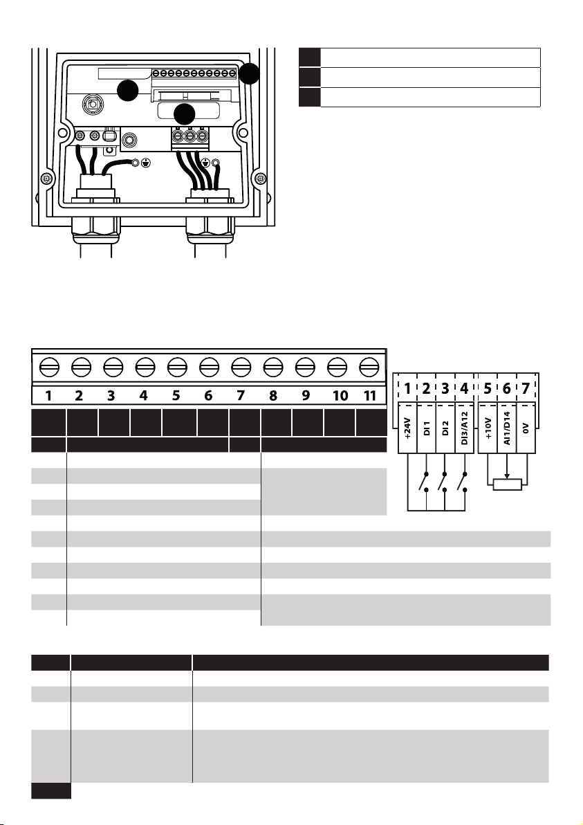
Analog Input AI1 Analog Input 1, signal format selected using P-16
Analog Input AI2 Analog Input 2, signal format selected using P-47
AI1 REF Analog Input 1 provides the speed reference
AI2 REF Analog Input 2 provides the speed reference
P-xx REF Speed reference from the selected preset speed
PR-REF Preset speeds P-20 – P-23 are used for the speed reference, selected according to other digital input
status
PI-REF PI Control Speed Reference
PI FB Analog Input used to provide a Feedback signal to the internal PI controller
KPD REF Keypad Speed Reference selected
FB REF Selected speed reference from Fieldbus (Modbus RTU / CAN Open / Master depending on P-12
setting)
(NO) Input is Normally Open, Close momentarily to activate the function
(NC) Input is Normally Closed, Open momentarily to activate the function
INC SPDNormally Open, Rising Edge, Close momentarily to increase the motor speed by value in P-20
DEC SPD
Normally Open, Rising Edge, Close momentarily to decrease the motor speed by value in P-20

Macro Functions – Terminal Mode (P-12 = 0)
P-15 DI1 DI2 DI3 / AI2 DI4 / AI1 Diagram
0 1 0 1 0 1 0 1
0STOP RUN FWD REV AI1 REF P-20 REF Analog Input AI1 1
1STOP RUN AI1 REF PR-REF P-20 P- 21 Analog Input AI1 1
2STOP RUN DI2 DI3 PR P-20 - P-23 P - 01 2
0 0 P-20
1 0 P - 21
0 1 P-22
1 1 P-23
3STOP RUN AI1 P-20 REF E-TRIP OK Analog Input AI1 3
4STOP RUN AI1 AI2 Analog Input AI2 Analog Input AI1 4
5STOP RUN FWD STOP RUN REV AI1 P-20 REF Analog Input AI1 1
^------FAST STOP (P-24)------^
6STOP RUN FWD REV E-TRIP OK Analog Input AI1 3
7STOP RUN FWD STOP RUN REV E-TRIP OK Analog Input AI1 3
^------FAST STOP (P-24)------^
8STOP RUN FWD REV DI3 DI4 PR 2
0 0 P-20
1 0 P - 21
0 1 P-22
1 1 P-23
9STOP START FWD STOP START REV DI3 DI4 PR 2
^------FAST STOP (P-24)------^ 0 0 P-20
1 0 P - 21
0 1 P-22
1 1 P-23
10 (NO) START STOP (NC) AI1 REF P-20 REF Analog Input AI1 5
11 (NO) START FWD
STOP (NC) (NO) START
REV
Analog Input AI1 6
^---------------------FAST STOP (P-24)---------------------^
12 STOP RUN FAST STOP
(P-24)
OK AI1 REF P-20 REF Analog Input AI1 7
13 (NO) START FWD STOP (NC) (NO) START REV KPD REF P-20 REF 13
^---------------------FAST STOP (P-24)---------------------^
14 STOP RUN DI2 E-TRIP OK DI2 DI4 PR 11
0 0 P-20
1 0 P - 21
0 1 P-22
1 1 P-23
15 STOP RUN P-23 REF AI1 Fire Mode Analog Input AI1 1
16 STOP RUN P-23 REF P-21 REF Fire Mode FWD REV 2
17 STOP RUN DI2 Fire Mode DI2 DI4 PR 2
0 0 P-20
1 0 P - 21
0 1 P-22
1 1 P-23
18 STOP RUN FWD REV Fire Mode Analog Input AI1 1

Macro Functions - Keypad Mode (P-12 = 1 or 2)
P-15 DI1 DI2 DI3 / AI2 DI4 / AI1 Diagram
0 1 0 1 0 1 0 1
0STOP ENABLE - INC SPD -DEC SPD FWD REV 8
^----------------START----------------^
1STOP ENABLE PI Speed Reference 2
2STOP ENABLE - INC SPD -DEC SPD KPD REF P-20 REF 8
^----------------START----------------^
3STOP ENABLE - INC SPD E-TRIP OK - DEC SPD 9
^-------------------------------START-------------------------------^
4STOP ENABLE - INC SPD KPD REF AI1 REF AI1 10
5STOP ENABLE FWD REV KPD REF AI1 REF AI1 1
6STOP ENABLE FWD REV E-TRIP OK KPD REF P-20 REF 11
7STOP RUN FWD STOP RUN REV E-TRIP OK KPD REF P-20 REF 11
^---------FAST STOP (P-24)---------^
8STOP RUN FWD STOP RUN REV KPD REF AI1 REF AI1 1
14 STOP ENABLE - INC SPD E-TRIP OK - DEC SPD
15 STOP ENABLE PR REF KPD REF Fire Mode P-23 P - 21 2
16 STOP ENABLE P-23 REF KPD REF Fire Mode FWD REV 2
17 STOP ENABLE KPD REF P-23 REF Fire Mode FWD REV 2
18 STOP ENABLE AI1 REF KPD REF Fire Mode AI1 1
9, 10, 11, 12, 13 = Behavior as per setting 0
NOTE
When P15=4 in keypad mode, DI2 &DI4 are edge triggered. Digital pot speed will be increased
or decreased once for each rising edge. The step of each speed change is defined by the absolute
value of Pre-set Speed 1 (P-20).
Speed change only happens during normal running condition (no stop command etc.). Digital pot
will be adjusted between minimum speed (P-02) and maximum speed (P-01).
Macro Functions - Fieldbus Control Mode (P-12 = 3, 4, 7, 8 or 9)
P-15 DI1 DI2 DI3 / AI2 DI4 / AI1 Diagram
0 1 0 1 0 1 0 1
0STOP ENABLE FB REF (Fieldbus Speed Reference, Modbus RTU / CAN / Master-Slave
defined by P-12)
14
1STOP ENABLE PI Speed Reference 15
3STOP ENABLE FB REF P-20 REF E-TRIP OK Analog Input AI1 3
5STOP ENABLE FB REF PR REF P-20 P- 21 Analog Input AI1 1
^----START (P-12 = 3 or 4 Only)----^
6STOP ENABLE FB REF AI1 REF E-TRIP OK Analog Input AI1 3
^----START (P-12 = 3 or 4 Only)----^
7STOP ENABLE FB REF KPD REF E-TRIP OK Analog Input AI1 3
^----START (P-12 = 3 or 4 Only)----^
14 STOP ENABLE - - E-TRIP OK Analog Input AI1 16
15 STOP ENABLE PR REF FB REF Fire Mode P-23 P - 21 2
16 STOP ENABLE P-23 REF FB REF Fire Mode Analog Input AI1 1
17 STOP ENABLE FB REF P-23 REF Fire Mode Analog Input AI1 1
18 STOP ENABLE AI1 REF FB REF Fire Mode Analog Input AI1 1
2, 4, 8, 9, 10, 11, 12, 13 = Behavior as per setting 0

Macro Functions - User PI Control Mode (P-12 = 5 or 6)
P-15 DI1 DI2 DI3 / AI2 DI4 / AI1 Diagram
0 1 0 1 0 1 0 1
0STOP RUN PI REF P-20 REF AI2 AI1 4
1STOP RUN PI REF AI1 REF AI2 (PI FB) AI1 4
3, 7 STOP RUN PI REF P-20 E-TRIP OK AI1 (PI FB) 3
4(NO) START (NC) STOP AI2 (PI FB) AI1 12
5(NO) START (NC) STOP PI REF P-20 REF AI1 (PI FB) 5
6(NO) START (NC) STOP E-TRIP OK AI1 (PI FB)
8STOP RUN FWD REV AI2 (PI FB) AI1 4
14 STOP RUN - - E-TRIP OK AI1 (PI FB) 16
15 STOP RUN P-23 REF PI REF Fire Mode AI1 (PI FB) 1
16 STOP RUN P-23 REF P-21 REF Fire Mode AI1 (PI FB) 1
17 STOP RUN P-21 REF P-23 REF Fire Mode AI1 (PI FB) 1
18 STOP RUN AI1 REF PI REF Fire Mode AI1 (PI FB) 1
2, 9, 10, 11, 12, 13 = Behavior as per setting 0
NOTE P1 Setpoint source is selected by P-44 (default is fixed value in P-45, AI 1 may also be selected).
P1 Feedback source is selected by P-46 (default is AI 2, other options may be selected).
Motor Thermistor Connection
Where a motor thermistor is to be used, it should be connected as follows:
Control Terminal Strip Additional Information
Compatible Thermistor: PTC Type, 2.5kΩ trip level.
Use a setting of P-15 that has Input 3 function as External Trip,
e.g. P-15 = 3. Refer to online documentation for further details.
Set P-47 = “"
5CHECK
6POWER ON

7COMMISSION
Operation
Managing the Keypad
The drive is configured and its operation monitored via the
keypad and display. DOWN
Used to decrease speed in real-time
mode or to decrease parameter values
in parameter edit mode.
START
When in keypad mode, used to Start a
stopped drive or to reverse the direction
of rotation if bi-directional keypad
mode is enabled.
NAVIGATE
Used to display real-time information,
to access and exit parameter edit mode
and to store parameter changes.
UP
Used to increase speed in real-time
mode or to increase parameter values
in parameter edit mode.
RESET /
STOP
Used to reset a tripped drive.
When in Keypad mode is used to Stop
a running drive.
Operating Displays
Drive Stopped /
Disabled
Drive is enabled
/ running, display
shows the output
frequency (Hz)
Press the Navigate
key for < 1 second.
The display will
show the motor
current (Amps)
Press the Navigate
key for < 1 second.
The display will
show the motor
power (kW)
If P-10 > 0, pressing
the
Navigate key
for < 1 second will
display the motor
speed (RPM)
Changing Parameters
Press and hold the
Navigate key > 2
seconds
Use the up and
down keys to
select the required
parameter
Press the Navigate
key for < 1 second
Adjust the value
using the Up and
Down keys
Press for < 1 second
to return to the
parameter menu
Press for > 2
seconds to return
to the operating
display
Read Only Parameter Access
Press and hold the
Navigate key > 2
seconds
Use the up and
down keys to select
P-00
Press the Navigate
key for < 1 second
Use the up and
down keys to select
the required Read
Only parameter
Press the Navigate
key for < 1 second
to display the value
Press and hold the
Navigate key > 2
seconds to return
to the operating
display
Resetting Parameters
To reset parameter values to
their factory default settings,
press and hold Up, Down and
Stop buttons for > 2 seconds.
The display will show “”
Press the Stop key. The
display will show “”
Resetting a Fault
Press the Stop key. The
display will show “”
7

8OPERATE
Parameters
Standard Parameters
Par. Description Min
Max
Default Units
P-01
Maximum Frequency/Speed Limit
P-02 500.0 50.0 (60.0) Hz/RPM
P-02 Minimum Frequency/Speed Limit 0.0 P-01 0.0 Hz/RPM
P-03 Acceleration Ramp Time 0.00 600.0 5.0 s
P-04 Deceleration Ramp Time 0.00 600.0 5.0 s
P-05 Stopping Mode/Mains Loss Response 0 4 0 -
Setting On Disable On Mains Loss
0 Ramp to Stop (P-04)
Ride Through (Recover energy from load to maintain operation)
1 Coast Coast
2 Ramp to Stop (P-04) Fast Ramp to Stop (P-24), Coast if P-24 = 0
3
Ramp to Stop (P-04) with AC Flux Braking
Fast Ramp to Stop (P-24), Coast if P-24 = 0
4
Ramp to Stop (P-04)
No action
P-06 Energy Optimiser 0 3 0 -
Setting Motor Energy Optimisation Drive Energy Optimisation
0 Disabled
Disabled
1 Enabled Disabled
2 Disabled Enabled
3
Enabled
Enabled
P-07
Motor Rated Voltage/Back
EMF at rated speed (PM/BLDC)
0 250/ 500 230/400 V
P-08 Motor Rated Current
Drive Rating Dependent
A
P-09 Motor Rated Frequency 10 500 50 (60) Hz
P-10 Motor Rated Speed 0 30000 0 RPM
The E3 drive normally uses frequency for all speed related parameters, e.g. Minimum and Maximum Output Frequency. It is also
possible to work directly in RPM, by setting P-10 to the rated speed from the motor nameplate.
When set to the default value of zero, all speed related parameters are displayed in Hz.
Entering the value from the motor nameplate enables the slip compensation function, and the drive display will also now show motor
speed in RPM. All speed related parameters, such as Minimum and Maximum Speed, Preset Speeds etc. will also be displayed in
RPM.
NOTE If P-09 value is changed, P-10 value is reset to 0.
P-11
Low Frequency Torque Boost
0.0
Drive Dependent
%
P-12 Primary Command Source 0 9 0 -
0: Terminal Control
1: Uni-directional Keypad Control
2: Bi-directional Keypad Control
3: Modbus Network Control
4: Modbus Network Control
5: PI Control
6: PI Analog Summation Control
7: CAN Control
8: CAN Control
9: Slave Mode
NOTE When P-12 = 1, 2, 3, 4, 7, 8 or 9, an enable signal must still be provided at the control terminals, digital input 1.
P-13 Operating Mode Select 0 2 0 -
0: Industrial Mode 1: Pump Mode 2: Fan Mode
Setting Appli-
cation
Current Limit
(P-54)
Torque
Characteristic
Spin Start
(P-33)
Thermal Overload Limit
Reaction (P-60 Index 2)
0 General 150% Constant 0: Off 0: Trip
1 Pump 110 % Variable 0: Off 1: Current Limit Reduction
2Fan 11 0 % Variable 2: On 1: Current Limit Reduction
P-14
Extended Menu Access code
0 65535 0 -
Enables access to Extended and Advanced Parameter Groups. This parameter must be set to the value programmed in P-37 (default:
101) to view and adjust Extended Parameters and value of P-37 + 100 to view and adjust Advanced Parameters. The code may be
changed by the user in P-37 if desired.

Extended Parameters
Par. Description Min
Max
Default Units
P-15
Digital Input Function Select
017 0 -
P-16 Analog Input 1 Signal Format See Below U0-10 -
U : Unidirectional, External 0 – 10Volt reference / pot
B : Bi-directional, External 0 – 10Volt reference / pot
: External 0 – 20mA signal
4 : External 4 – 20mA signal, trip on loss
4 : External 4 – 20mA signal, P-20 on loss
4 : External 20 – 4mA signal, trip on loss
4 : External 20 – 4mA signal
U : External 10 – 0 Volt signal
n : Switched units only : Internal pot
P-18 Output Relay Function Select 0 9 1 -
0: Drive Enabled (Running)
1: Drive Healthy
2: At Target Frequency (Speed)
3: Drive Tripped
4: Output Frequency >= Limit
5: Output Current >= Limit
6: Output Frequency < Limit
7: Output Current < Limit
8: Analog Input 2 > Limit
9: Drive Ready to Run
P-20
Preset Frequency / Speed 1
-P-01 P-01 5.0 Hz/RPM
P-21
Preset Frequency / Speed 2
-P-01 P-01 25.0 Hz/RPM
P-22
Preset Frequency / Speed 3
-P-01 P-01 40.0 Hz/RPM
P-23
Preset Frequency / Speed 4
-P-01 P-01 P-09 Hz/RPM
P-24 2nd Ramp Time (Fast Stop) 0.00 600.0 0.00 s
P-25 Analog Output Function Select 0
11 8
-
Digital Output Mode. Logic 1 = +24V DC Analog Output Mode
0: Drive Enabled (Running)
1: Drive Healthy
2: At Target Frequency (Speed)
3: Drive Tripped
4: Output Frequency >= Limit
5: Output Current >= Limit
6: Output Frequency < Limit
7: Output Current < Limit
8: Output Frequency (Motor Speed)
9: Output (Motor) Current
10: Output Power
11: Load Current
P-30 Start/ Restart / Fire Mode Configuration
Index 1: Start Mode / Auto Restart N/A Edge-r -
: Following Power on or reset, the drive will not start if Digital Input 1 remains closed. The Input must be closed after a power
on or reset to start the drive.
: Following a Power On or Reset, the drive will automatically start if Digital Input 1 is closed.
To : Following a trip, the drive will make up to 5 attempts to restart at 20 second intervals.
Index 2: Fire Mode Input Logic 0 1 0 -
0: Normally Closed (NC) input. Fire Mode active if input is open.
1: Normally Open (NO) input. Fire Mode active if input is closed.
Index 3: Fire Mode Input Latch 0 1 0 -
0: Latched input. The drive will remain in Fire Mode, only as long the fire mode input signal remains.
1: Momentary input. Fire Mode is activated by a momentary signal on the input. Normally Open or Normally Closed
operation is supported depending on Index 2 setting.
2: Normally Closed (NC) Input, Preset Speed 4 (P-23).
3: Normally Open (NO) Input, Preset Speed 4 (P-23).
P-31 Keypad Start Mode Select 0 - 3 7 1 -
0: Minimum Speed, Keypad Start
1: Previous Speed, Keypad Start
2: Minimum Speed, Terminal Enable
3: Previous Speed, Terminal Enable
4: Current Speed, Keypad Start
5: Preset Speed 4, Keypad Start
6: Current Speed, Terminal Start
7: Preset Speed 4, Terminal Start
P-33 Spin Start 0 2 0 -
0: Disabled
1: Enabled
2: Enabled on Trip, Brown Out or Coast Stop
P-34 Brake Chopper Enable (Not Size 1) 0 4 0 -
0: Disabled
1: Enabled With Software Protection
2: Enabled Without Software Protection
3: Enabled With Software Protection
4: Enabled Without Software Protection

Par. Description Min
Max
Default Units
P-38 Parameter Access Lock 0 1 0 -
0: Unlocked 1: Locked
P-39 Analog Input 1 Offset
-500.0
500.0 0.0 %
P-40
Index 1: Display Scaling Factor
0.000 16.000 0.000 -
Index 2: Display Scaling Source
0 3 0 -
P-41
PI Controller Proportional Gain
0.0 30.0 1.0 -
P-42 PI Controller Integral Time 0.0 30.0 1.0 s
P-43 PI Controller Operating Mode 0 3 0 -
0: Direct Operation
1: Inverse Operation
2: Direct Operation, Wake at Full Speed
3: Reverse Operation, Wake at Full Speed
P-44 PI Reference (Setpoint) Source Select 0 1 0 -
0: Digital Preset Setpoint 1: Analog Input 1 Setpoint
P-45 PI Digital Setpoint 0.0 100.0 0.0 %
P-46 PI Feedback Source Select 0 5 0 -
0: Analog Input 2
1: Analog Input 1
2: Motor Current
3: DC Bus Voltage
4: Analog 1 – Analog 2
5: Largest (Analog 1, Analog 2)
P-47 Analog Input 2 Signal Format - - - U0-10
U : Unidirectional, External 0 – 10Volt reference / pot
: External 0 – 20mA signal
4 : External 4 – 20mA signal, trip on loss
4 : External 4 – 20mA signal, P-20 on loss
4 : External 20 – 4mA signal, trip on loss
4 : External 20 – 4mA signal
: Motor thermistor
P-48 Standby Mode Timer 0.0 25.0 0.0 s
P-49
PI Control Wake Up Error Level
0.0 100.0 5.0 %
P-50 User Output Relay Hysteresis 0.0 100.0 0.0 %
Advanced Parameters
Par. Description Min
Max
Default Units
P-51 Motor Control Mode 0 5 0 -
0: Vector speed control mode
1: V/f mode
2: PM motor vector speed control
3: BLDC motor vector speed control
4: Synchronous Reluctance motor vector speed control
5: LSPM motor vector speed control
P-52 Motor Parameter Autotune 0 1 0 -
0: Disabled 1: Enabled
P-54 Maximum Current Limit 0 175 15 0 %
Defines the max current limit in vector control modes
P-61 Ethernet Service Option 0 1 0 -
0: Disabled 1: Enabled
P-62 Ethernet Service Timeout 0 60 0 Mins
0: Disabled >0: Timeout in minutes
P-63 Modbus Mode Selection 0 1 0 -
0: Standard11: Advanced2
P-64 IP66 DI1 Source 0 4 0 -
Visible only on IP66 Switched Drives
0: Terminal 2 OR Switch Forward OR Switch Reverse
1: Terminal 2 Only
2: Terminal 2 OR Switch Forward
3: Terminal 2 AND (S-Forward OR Switch Reverse)
4: Terminal 2 AND Switch Forward
P-65 IP66 DI2 Source 0 2 0 -
Visible only on IP66 Switched Drive
0: Terminal 3 OR Switch Reverse
1: Terminal 3 Only
2: Terminal 3 AND Switch Reverse

Asynchronous Induction Motors (IM) Vector Control
The E3 drive factory default parameters are intended for use with IM motors where the power rating of the motor is
approximately the same or slightly less than the indicated power rating of the drive. In this case, it should be possible to
operate the motor without any parameter adjustment at all for initial testing.
For optimum performance, the drive parameters should be adjusted to match the motor ratings. This will also ensure correct
protection of the motor from damage due to overload.
The basic parameters that should be adjusted are:
P-07 : Motor Rated Voltage (V)
P-08 : Motor Rated Current (A)
P-09 : Motor Rated Frequency (Hz)
In addition, it is also possible to set:
P-10 : Motor Rated Speed (RPM)
When this parameter is adjusted, slip compensation is activated. Slip compensation attempts to compensate the motor speed
relative to the load applied, such that when operating at a constant speed with different loads, the motor shaft speed should
remain approximately the same.
To further improve the performance of the motor, the following additional steps can be followed:
Carry out an Autotune.
o This requires Advanced Parameter Access, P-14 = P-37 + 100 (Default : 201).
o After the correct nameplate information is entered from the motor, the drive can additionally measure some electrical
characteristics of the motor to further optimise the motor control to suit connected motor.
o This is achieved by setting P-52 = 1.
The autotune will begin IMMEDIATELY following the setting of this parameter!
o The drive output will be enabled, and the motor shaft may move. It is important to ensure this is safe before carrying out
the autotune.
o For IM motors, the autotune takes only a few seconds, and measures only the motor stator resistance. Parameter P-55 will
be updated with the new value.
Adjust the Low Frequency Torque Boost
o IM motors require some additional voltage at low frequency to improve the low speed operation and torque.
o By adjusting P-11, it is possible to optimise the low speed operation.
o If P-11 is increased too far, excessive motor heating or over current trips may result.
Speed regulation and response to load changes may be improved by adjusting P-11 Vector Gain to suit the motor and
connected load.
o Higher values will provide a more dynamic behaviour at the risk of instability.
NOTE For other motor types refer to online document.

Technical Data
Environment
Operational ambient temperature range
Enclosed Drives: -20 ... 40°C (frost and condensation free)
Storage ambient temperature range: -40 … 60°C
Maximum altitude: 2000m. Derate above 1000m: 1% / 100m
Maximum humidity: 95%, non-condensing
Rating Tables
Frame
Size
kW HP
Input
Current
Fuse/MCB
(Type B)
Maximum Cable
Size
Output
Current
Recommended
Brake Resistance
Non UL UL mm
AWG
A Ω
110 - 115 (+ / - 10%) V 1 Phase Input, 230V 3 Phase Output (Voltage Doubler)
1 0.37 0.5 7. 8 10 10 8 8 2.3 -
10.75 115 . 8 25 20 8 8 4.3 -
21.1 1.5 21.9 32 30 8 8 5.8 10 0
200 - 240 (+ / - 10%) V 1 Phase Input, 3 Phase Output
1 0.37 0.5 3.7 10 6 8 8 2.3 -
10.75 17. 5 10 10 8 8 4.3 -
11.5 212 . 9 16 17. 5 8 8 7 -
21.5 212 . 9 16 17. 5 887 100
2 2.2 3 19 . 2 25 25 8 8 10.5 50
3 4 5 29.2 40 40 8 8 15 . 3 25
200 - 240 (+ / - 10%) V 3 Phase Input, 3 Phase Output
1 0.37 0.5 3.4 6 6 8 8 2.3 -
10.75 15.6 10 10 8 8 4.3 -
11.5 28.9 16 15 8 8 7 -
21.5 28.9 16 15 887 10 0
2 2.2 3 12 .1 16 17. 5 8 8 10.5 50
3 4 5 20.9 32 30 8 8 18 25
35.5 7. 5 26.4 40 35 8 8 24 20
47. 5 10 33.3 40 45 16 5 30 15
411 15 50.1 63 70 16 5 46 10
380 - 480 (+ / - 10%)V 3 Phase Input, 3 Phase Output
10.75 13.5 6 6 8 8 2.2 -
11.5 25.6 10 10 8 8 4 .1 -
21.5 25.6 10 10 8 8 4 .1 250
2 2.2 3 7. 5 16 10 8 8 5.8 200
2 4 5 11 . 5 16 15 8 8 9.5 12 0
35.5 7. 5 17. 2 25 25 8 8 14 100
37. 5 10 21. 2 32 30 8 8 18 80
311 15 2 7. 5 40 35 8 8 24 50
415 20 34.2 40 45 16 5 30 30
4 18.5 25 44.1 50 60 16 5 39 22
422 30 51.9 63 70 16 5 46 22
NOTE Cable sizes shown are the maximum possible that may be connected to the drive. Cables should be selected
according to local wiring codes or regulations at the point of installation.

Troubleshooting
Fault Code Messages
Fault Code
No. Description Suggested Remedy
n 00 No Fault Not required.
01 Brake channel over current Check external brake resistor condition and connection wiring.
02 Brake resistor overload The drive has tripped to prevent damage to the brake resistor.
03 Output Over Current Instantaneous Over current on the drive output. Excess load or shock load on
the motor.
NOTE Following a trip, the drive cannot be immediately reset. A delay time
is inbuilt, which allows the power components of the drive time to recover to
avoid damage.
04
Motor Thermal Overload (I2t)
The drive has tripped after delivering >100% of value in P-08 for a period of
time to prevent damage to the motor.
06 Over voltage on DC bus Check the supply voltage is within the allowed tolerance for the drive. If the
fault occurs on deceleration or stopping, increase the deceleration time in
P-04 or install a suitable brake resistor and activate the dynamic braking
function with P-34.
U 07 Under voltage on DC bus The incoming supply voltage is too low. This trip occurs routinely when power
is removed from the drive. If it occurs during running, check the incoming
power supply voltage and all components in the power feed line to the drive.
08 Heatsink over temperature The drive is too hot. Check the ambient temperature around the drive is within
the drive specification. Ensure sufficient cooling air is free to circulate around
the drive.
U 09 Under temperature The drive temperature is below the minimum limit and must be increased to
operate the drive.
10 Factory Default parameters
loaded
11 External trip E-trip requested on digital input 3. Normally closed contact has opened. If
motor thermistor is connected check if the motor is too hot.
12 Optibus comms loss Check communication link between drive and external devices. Make sure
each drive in the network has its unique address.
13 DC bus ripple too high Check incoming supply phases are all present and balanced.
14 Input phase loss trip Check incoming power supply phases are present and balanced.
15 Output Over Current Check for short circuits on the motor and connection cable.
NOTE Following a trip, the drive cannot be immediately reset. A delay time
is inbuilt, which allows the power components of the drive time to recover to
avoid damage.
16 Faulty thermistor on heatsink
17 Internal memory fault (IO) Press the stop key. If the fault persists, consult you supplier.
4 18 4-20mA Signal Lost Check the analog input connection(s).
19 Internal memory fault (DSP) Press the stop key. If the fault persists, consult you supplier.
21 Motor PTC thermistor trip Connected motor thermistor over temperature, check wiring connections and
motor.
22 Cooling Fan Fault (IP66 only) Check / replace the cooling fan.
23
Drive internal temperature
too high
Drive ambient temperature too high, check adequate cooling air is provided.
U 26 Output Fault Indicates a fault on the output of the drive, such as one phase missing, motor
phase currents not balanced. Check the motor and connections.

Fault Code
No. Description Suggested Remedy
41 Autotune Fault The motor parameters measured through the autotune are not correct.
Check the motor cable and connections for continuity.
Check all three phases of the motor are present and balanced.
50 Modbus comms loss fault Check the incoming Modbus RTU connection cable.
Check that at least one register is being polled cyclically within the timeout
limit set in P-36 Index 3.
51 CAN comms loss trip Check the incoming CAN connection cable.
Check that cyclic communications take place within the timeout limit set in
P-36 Index 3.
NOTE Following an over current or overload trip (1, 3, 4, 15), the drive may not be reset until the reset time delay has elapsed
to prevent damage to the drive.
drive.web Distributed Control Technology
drive.web Distributed Control Technology provides high performance, peer-to-peer networking over Ethernet and
completely homogeneous systems integration for all Bardac AC and DC drive models, drive.web smart programmmable
controllers, flexible i/o, and savvyPanel industrial touch screens.
Easily build a completely integrated enterprise ... machine to management
drive.web distributed control enables processessing resources to be shared between devices thereby ensuring cost
effective, full featured control for systems of any size or complexity. Peer-to-peer connections eliminate the constraints
imposed by a PLC in a conventionl control system.
• configure, monitor and control all your drives and devices from anywhere
• entire configurations are saved in the devices - you are not dependent on external storage or the “cloud”.
• provides full featured PAC, PLC and motion control functions on board
• add unlimited distributed smart i/o - precision analog, logic, encoders, RTDs, sensors, steppers
• build and document complete systems
• secure with multi-layer password protection and VPN access
• includes event driven email, network watchdogs, graphical state machine logic, IIoT tools, Internet access, a future.
Other manuals for E3 Series
1
Table of contents
Other Bardac DC Drive manuals
Popular DC Drive manuals by other brands

ABB
ABB ACS880-11 manual

Danfoss
Danfoss VLT FC 103 operating instructions

Dakota Digital
Dakota Digital ECD-100 quick start guide

Milltronics
Milltronics Sigma2 VM16 Electrical Manual

Delta Electronics
Delta Electronics AC Motor Drive VFD-E user manual

Rockwell Automation
Rockwell Automation Allen-Bradley PowerFlex 4 FKN6 Series quick start

Emotron
Emotron VFX 2.0 instruction manual

Copley Controls
Copley Controls Accelnet manual

Rexnord
Rexnord Falk Quadrive A owner's manual

YASKAWA
YASKAWA CIPR-GA50UB001AJ Series Installation & Primary Operation

Sprint Electric
Sprint Electric 400 product manual

YASKAWA
YASKAWA SI-T3 MECHATROLINK-II A1000 Series installation manual