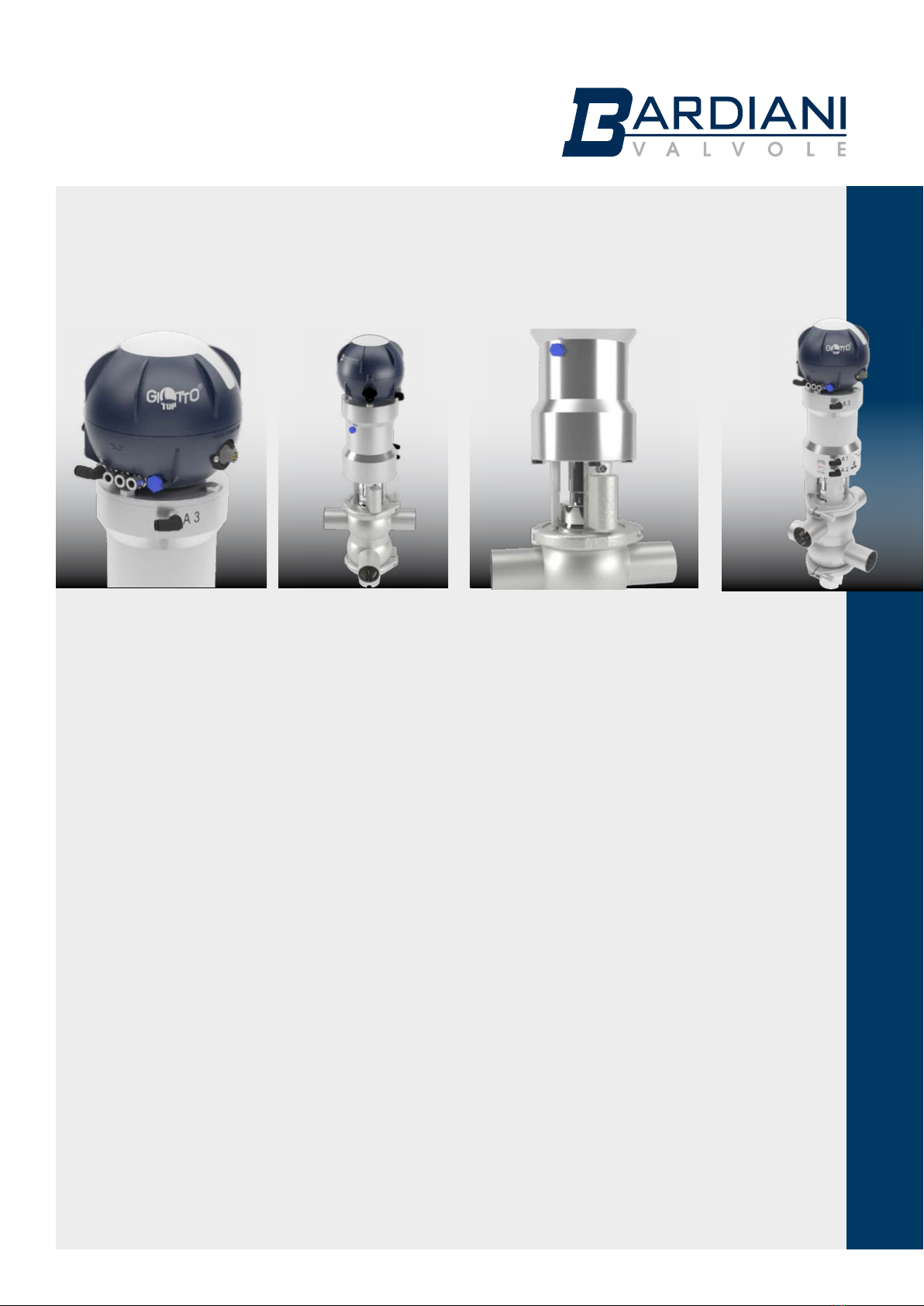
Bardiani Valvole B925 Specification sheet
Other Bardiani Valvole Control Unit manuals

Bardiani Valvole
Bardiani Valvole B925 User manual

Bardiani Valvole
Bardiani Valvole BBZS1 Specification sheet

Bardiani Valvole
Bardiani Valvole BBZO Specification sheet

Bardiani Valvole
Bardiani Valvole BBZS5 Specification sheet

Bardiani Valvole
Bardiani Valvole BBZPM User manual

Bardiani Valvole
Bardiani Valvole GIOTTO TOP Specification sheet

Bardiani Valvole
Bardiani Valvole BBZS1 Manual

Bardiani Valvole
Bardiani Valvole BBZK Specification sheet

Bardiani Valvole
Bardiani Valvole BZAW3 Specification sheet

Bardiani Valvole
Bardiani Valvole BBWMF1 Specification sheet

Bardiani Valvole
Bardiani Valvole MIXPROOF B915PMO Specification sheet

Bardiani Valvole
Bardiani Valvole J-GIOTTO TOP Specification sheet

Bardiani Valvole
Bardiani Valvole BBZO BBZOG User manual

Bardiani Valvole
Bardiani Valvole J-GIOTTO TOP Specification sheet

Bardiani Valvole
Bardiani Valvole BBZK Manual

Bardiani Valvole
Bardiani Valvole BBZM Specification sheet

Bardiani Valvole
Bardiani Valvole VVF Series Specification sheet
Popular Control Unit manuals by other brands

Festo
Festo Compact Performance CP-FB6-E Brief description

Elo TouchSystems
Elo TouchSystems DMS-SA19P-EXTME Quick installation guide

JS Automation
JS Automation MPC3034A user manual

JAUDT
JAUDT SW GII 6406 Series Translation of the original operating instructions

Spektrum
Spektrum Air Module System manual

BOC Edwards
BOC Edwards Q Series instruction manual

KHADAS
KHADAS BT Magic quick start

Etherma
Etherma eNEXHO-IL Assembly and operating instructions

PMFoundations
PMFoundations Attenuverter Assembly guide

GEA
GEA VARIVENT Operating instruction

Walther Systemtechnik
Walther Systemtechnik VMS-05 Assembly instructions

Altronix
Altronix LINQ8PD Installation and programming manual