Barksdale BNA 21 User manual
Operating Instructions
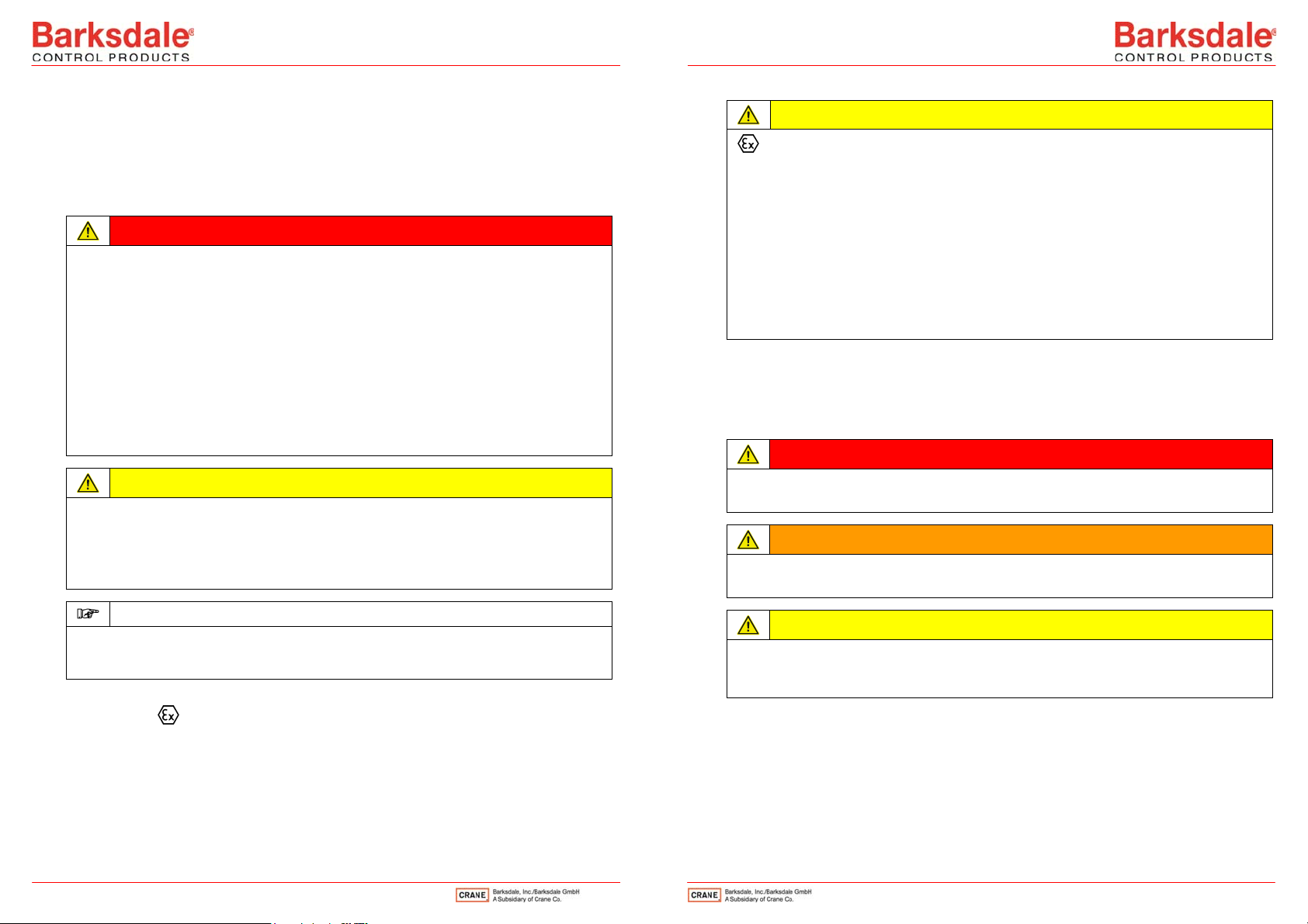
Bypass level indicator
1Intended Applications ................................................................................................... 2
2Safety Instructions......................................................................................................... 3
3Standards ....................................................................................................................... 4
4Warranty/Guaranty......................................................................................................... 4
5Principle of Operation ................................................................................................... 5
6Installation/Commissioning .......................................................................................... 6
7Maintenance ................................................................................................................. 10
8Technical Data.............................................................................................................. 11
9EU type examination certificate.................................................................................. 12
Barksdale GmbH
Dorn-Assenheimer Straße 27
D-61203 Reichelsheim
Phone: +49 (6035) 949-0
Fax: +49 (6035) 949-111 and 949-113
Internet: www.barksdale.de
1
14
Art. no.: 923-0664
Index G, 03.07.2019
Specifications are subject to
changes without notice!
Refer to data sheet for further
technical data.
Intended Applications
The Bypass Level Indicator (BNA) serves exclusively for indicating the level corresponding to that of
the connected tank. Control devices such as solenoid switches or remote indicators can be
additionally installed by Barksdale.
The manufacturer assumes the responsibility for correct execution of the equipment according to
the orderer's instructions. The orderer assumes the responsibility for the correct installation and use
of the equipment subject to the applicable national regulations.
DANGER
Read the operating instructions and the safety instructions carefully before using the Bypass
Level Indicator. Nonobservance may cause injuries to health or material damage.
Barksdale GmbH cannot be held liable for any damage resulting from incorrect use.
The Bypass Level Indicators (BNA) must not be used in situations in which lives depend on
proper functioning of the equipment.
The Bypass Level Indicator may only be used in the specified fields of application and with the
permissible data (see nameplate). The temperature ranges must be within the permissible limits.
The stated pressures and electrical load values must not be exceeded.
The orderer ensures that exothermic reactions or spontaneous gas-phase formation of the
medium are impossible.
Observe also the applicable national safety instructions for assembly, commissioning and
operation of the Bypass Level Indicator.
CAUTION
If the medium is water and there is a risk of icing the water must be discharged from the Bypass
Level Indicator (BNA) or heating must be provided to prevent damage to the float or the indicator
tube.
The maximum speed of the float caused by level changes must not exceed 1 m/s. If necessary a
suitable screen must be installed by the orderer in the connection to the tank.
NOTE
Unless agreed otherwise the Bypass Level Indicator (BNA) is designed for static operating
conditions. If any vibrations are to be expected, e.g. by pumps, compressors etc. the orderer
must provide for adequate vibration absorption.
The classification of ex devices is stated on the nameplate and the EC type examination certificate.
The designation II 1G Ex h IIC T6…T1 Ga permits use in potentially explosive gas atmosphere
outside the equipment in zone 0. Inside the equipment zone 0 is also permitted.
CAUTION
In ex areas the orderer must not use any plastic bypass level indicators (BNA) because
of the risk of electrostatic charging.
If the Bypass Level Indicator (BNA) is determined for use in potentially explosive
atmosphere, it must be checked whether the damper has been installed in the lower
flange. The BNA must be suitable for the intended use according to its nameplate.
In case of use in zone 0, the maximum process temperatures according to the
temperature class and the permissible pressure range in the tank of 0.8 to 1.1 bar
absolute in case of potentially explosive temperature must be observed. If the Bypass
Level Indicator (BNA) is used in a potentially explosive atmosphere outside the
permissible pressure range and temperature range in the tank mentioned above, the type
examination certificate serves only as a guideline.
Additional examinations for the specific operating conditions are recommended.
Safety Instructions
The safety instructions are intended to protect the user from dangerous situations and/or prevent
material damage.
In the operating instructions the seriousness of the potential risk is designated by the following
signal words:
DANGER
Refers to imminent danger to men.
Nonobservance may result in fatal injuries.
WARNING
Refers to a recognizable danger.
Nonobservance may result in fatal injuries, and destroy the equipment or plant parts.
CAUTION
Refers to a danger.
Nonobservance may result in minor injury and damage to the Bypass Level Indicator (BNA)
and/or the plant.
3
2

NOTE
Refers to important information essential to the user.
Disposal
The Bypass Level Indicator must be disposed of correctly in accordance with the local
regulations for electric/electronic equipment.
The Bypass Level Indicator must not be disposed of with the household garbage!
Standards
The standards applied during development, manufacture and configuration are listed in the CE
conformity and manufacturer's declaration.
Warranty/Guaranty
Warranty
Our scope of delivery and services is governed by the legal warranties and warranty periods.
Terms of guaranty
We guaranty for function and material of the Bypass Level Indicator under normal operating and
maintenance conditions in accordance with the statutory provisions.
Loss of guaranty
The agreed guaranty period will expire in case of:
incorrect use
modifications to the equipment
incorrect installation
incorrect handling or operation contrary to the provisions of these operating instructions
No liability is assumed for any damage resulting therefrom, or any consequential damage.
Principle of Operation
Figure 1: Sectional drawing BNA Figure 2:Detail - level indication BNA
The Bypass Level Indicator (BNA) works according to the principle of operation shown in figure 1.
The tank to be monitored (1/1) is connected with the Bypass Level Indicator (1/4) by two
connecting lines (1/2 and 1/3). The liquid to be measured is always at the same level in the tank
and in the Bypass Level Indicator.
The float (1/5) contains a magnetic system which acts on the one hand on the magnetic flags of
the indication bar (1/7) and on the other hand on the limit switches (1/8) or on the electric
transmitter (1/9).
5
4

Installation/Commissioning
DANGER
The electrical connection may only be made by trained expert staff!
Prior to any work on electrical components disconnect them from power supply.
NOTE
When the equipment is used in potentially explosive atmosphere chapter 0 „Intended
Applications“ must be observed!
If the Bypass Level Indicator (BNA) is determined for use in potentially explosive
atmosphere, it must be checked whether the damper has been installed in the lower
flange. The BNA must be suitable for the intended use according to its nameplate.
DANGER
In ex areas, only equipment which is in conformity with ATEX may be used.
EN 60079-14 must be observed.
The BNA-EX must be integrated in the potential equalisation system via the tubing during
installation.
Metallic process connection parts have to be included in the local potential equalization.
The Bypass Level Indicator type BNA-S../..EX…MA….has to be installed and used in
such a way that electrostatic charging from operation, maintenance or cleaning is
excluded.
NOTE
Before further steps are taken the orderer must check whether the operating conditions agreed in
the order are still valid. The equipment must be suitable for the intended purpose. This applies in
particular to:
the pressure, temperature, medium characteristics
the classification according to the Pressure Equipment Directive
possible additional loads
Mechanical installation
Bypass Level Indicators (BNA) are measuring devices. Perform all work on BNA with utmost care.
Check whether the Bypass Level Indicator (BNA) supplied is in conformity with your order
specification.
Check whether all parts are available and that the connection flanges of tank and indicator match.
The float has been packaged and attached to the outside of the Bypass Level Indicator (BNA).
Remove the bottom connection flange (1/10) from the BNA.
Insert the float into the BNA in such a way that the mark (Top) points up.
Attach the bottom connection flange with its gasket to the BNA.
Tighten all screws crosswise.
CAUTION
During erection of the Bypass Level Indicator (BNA) the float may be damaged by bumping.
Erect the Bypass Level Indicator (BNA) slowly and carefully.
CAUTION
Frozen fluids on or in the Bypass Level Indicator (BNA) may cause faults or total failure.
If no liquid process medium can be guaranteed at low outdoor temperatures (risk of fluid
freezing) the BNA must be protected against frost by suitable measures or emptied completely.
CAUTION
Thermal hazard from hot/cold surface of Bypass Level Indicator (BNA)
Do not touch the BNA with your bare hands. Wear protective gloves.
DANGER
Depressurize the system before carrying out any work on the Bypass Level Indicator (BNA)!
7
6
NOTE
Ensure that the flanges of the tank are accurately aligned with the flanges of the BNA.
Non-alignment of the flanges causes seizing or distortion of the BNA (1/4). The float (1/5) may
get jammed.
The principle of operation of the Bypass Level Indicator is based on the magnetic field principle.
No magnetic iron parts (e. g. screws, clamps etc.) must be used in the vicinity of the level tube.
Observe the data in chapter 8 „Technical Data“.
Install the BNA so that the nameplate (1/11) of the BNA (1/4) is located at the bottom.
Align all indication rotors (2/12) by means of a magnet or the enclosed float. All rotors must
show the colour white or silver;
white: makrolon, medium temperature up to 150 °C or aluminium, medium temperature up to 350 °C
silver: aluminium, medium temperature up to 200 °C
The maximum ambient temperature is 120 °C.
Ensure that all flange attachment screws, the vent plug (1/13) and the drain screw (1/14) are
tightened or closed properly.
Torques for the screws:
Type Screw dimension Torque [Nm]
X1 M12 50
Plug G½, ½“ NPT 80
Fastening clamp 7 mm hexagon head 0.75
Electrical installation
DANGER
The orderer must ensure that all applicable regulations are observed in the event that electric
limit switches and remote indicators are used.
For further information about installation of the electric limit switches and remote indicators refer to
the corresponding installation and operating instructions.
Commissioning
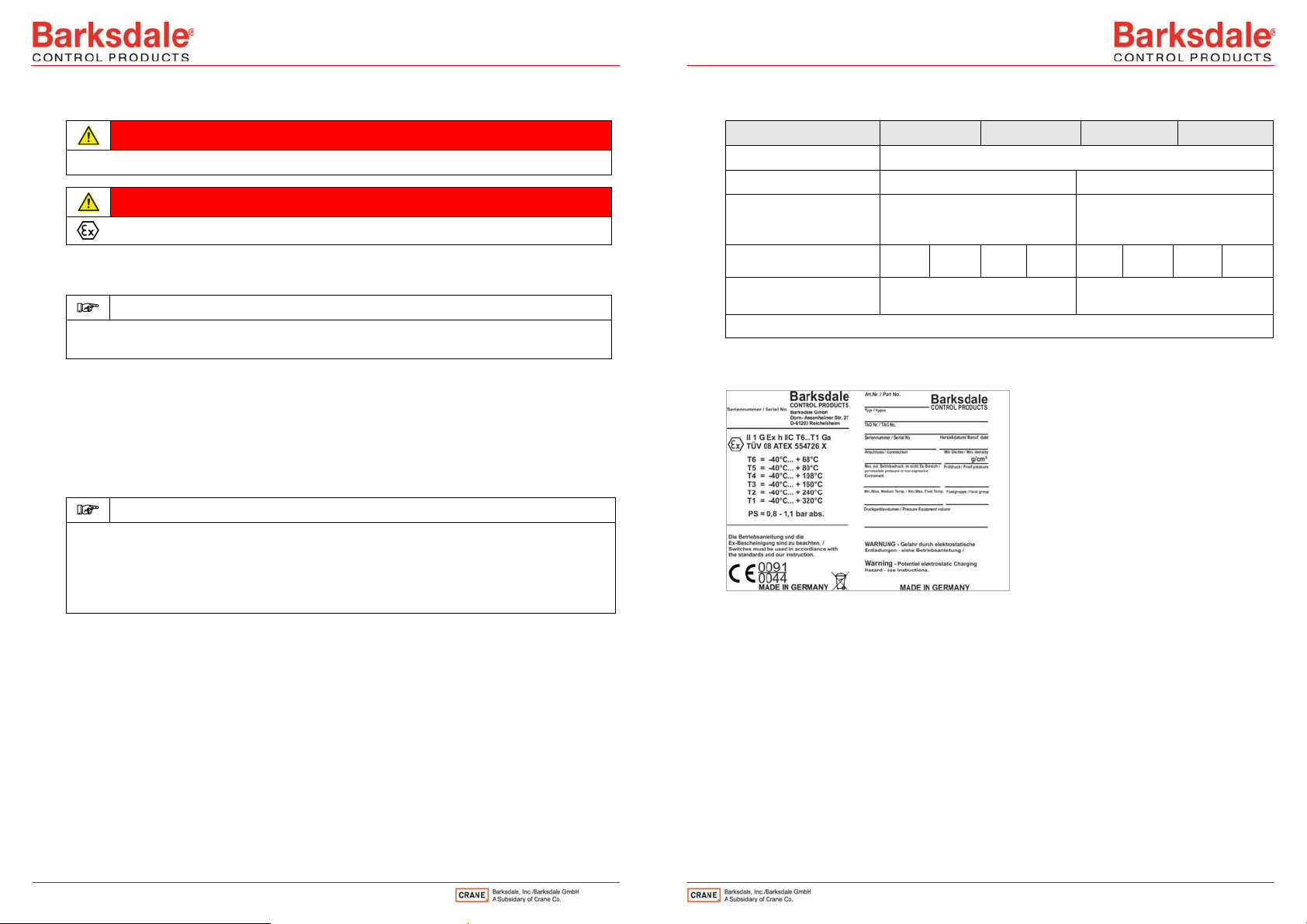
The Bypass Level Indicators (BNA) are specially made for a specific application. The most
important data, such as flange, pressure, temperature and min. specific gravity of the float are
specified on the nameplate (1/11).
Check prior to commissioning whether the technical data according to the nameplate are in
agreement with the plant requirements.
Operating pressure and operating temperature of the plant must not exceed the data stated on the
nameplate of the Bypass Level Indicator. Exceeding the limit values will cause changes in the
behaviour and service life of the BNA. If the proof pressure is exceeded, functioning of the BNA is
no longer guaranteed and the BNA may be damaged.
Ensure that - dependent on the type of medium to be measured - the appropriate safety
precautions are taken.
Filling the Bypass Level Indicator
Slowly open the top valve (1/2a).
Slowly open the bottom valve (1/3b).
The liquid rises slowly in the BNA (1/4). The float (1/5) is lifted until the same level is reached in the
tank (1/1) and in the BNA.
Fully open the bottom valve (1/3b).
NOTE
For pressures above 40 bar a vented float (additional designation: -VAE) is used which is
provided with a small pressure compensation tube.
When using the VAE version take care that the temperature in the BNA and in the float rises
evenly and slowly. The use of vented floats should be discussed with the manufacturer
beforehand.
9
8
Maintenance
DANGER
Depressurize the system before carrying out any work on the Bypass Level Indicator (BNA)!
DANGER
Maintenance must not be performed in a potentially explosive atmosphere.
If the liquid to be measured contains dirt particles which may deposit in the bottom part of the BNA:
Determine the necessary time interval for cleaning.
NOTE
Coated Bypass Level Indicators must be checked regularly - at least every 12 months - for
damage to the coating.
Cleaning
Open the drain plug (1/14) or drain valve. Wash out the deposits.
If there are any encrustations, remove the top and bottom flange (dependent on the model).
Carefully remove the float.
Clean the BNA mechanically.
Check all flanges, discharge tubes and vent plugs for firm seat and tightness at regular
intervals.
Check the gaskets carefully. Replace graphite gaskets immediately when damaged.
NOTE
The orderer must ensure that the inspection intervals required for his plant are observed.
Indicators provided with a heating jacket covering the inner weld seams must be subjected to a
pressure chamber leak test at intervals to be specified by the operator. This is to recognize
corrosion-conditioned leaks of a weld seam exposed to the process medium, and to prevent that
process medium from entering the heating circuit.
8 Technical Data
BNA 21/22 BNA 31/36 BNA 41/42 BNA 45/46
Tube and flange material 1.4571
Float material 1.4571 or titanium 1.4571 or titanium
Media temperature range Max. -40°C…+ 150°C
(ex area according to ATEX
see certificate)
Max. -40°C…+ 320°C
(ex area according to ATEX
see certificate)
Process connection G1/2“ on the
side
G1/2“ on the
side
G1/2“ on the
side
G1/2“ on the
side
Maximum permissible
pressure
PN 16 PN 40
Refer to data sheets for further technical data, dimensions and options
Nameplate
For ex equipment (example)
.
11
10
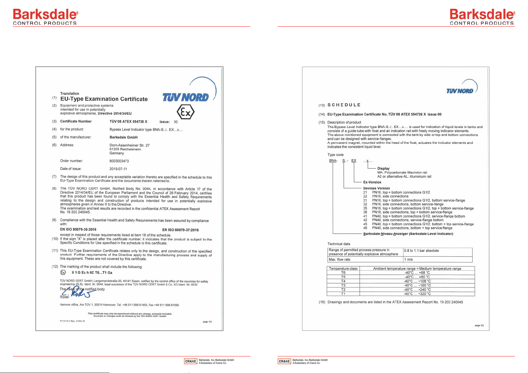
9 EU type examination certificate
Ex equipment: observe the EU type examination certificate
12 13
This manual suits for next models
7
Table of contents
Other Barksdale Measuring Instrument manuals


Popular Measuring Instrument manuals by other brands

Eddyfi Technologies
Eddyfi Technologies GEKKO M2M Technical documentation

Schmidt
Schmidt Paper Schmidt PS8000 quick reference

Gemlogis
Gemlogis VISTA quick start guide

PCE Instruments
PCE Instruments PCE-DC 41 manual

CGOLDENWALL
CGOLDENWALL NDJ-5S user manual

southern electric
southern electric iplan user guide


Emerson Research
Emerson Research X-STREAM Series Instruction manual addendum

PCE Health and Fitness
PCE Health and Fitness PCE-HT 120 user manual

eXact
eXact idip quick start guide

PCB Piezotronics
PCB Piezotronics 356A36 Installation and operating manual

Gasmet
Gasmet GT5000 quick guide

Shimadzu
Shimadzu IRAffinity-1 instruction manual