Art.-Nr.: 923-2817
Index ---, 16.03.2021
Specifications are subject to
changes without notice.
21
1. Installation
Operating of the BFS-40 N/L flow monitors and indicators is based on the movement of a
spring-loaded piston within a cylindrical tube. The instrument can be mounted in any position
in a system. Flow direction is from the lowest to the highest value, indicated on the scale.
The flow media must be free of particle contamination, otherwise the instruments will not func-
tion properly. Particularly magnetic particles may cause faults. We recommend the use of dirt
filters or magnetic filters. All non standard applications should be discussed with our technical
engineers.
The flow monitors must not be positioned in inductive or magnetic fields. Minimum distance
from iron parts: 10 mm.
All connection sizes comply with the R-standard (DIN 2999, part 1). Only suitable thread and
sealing material should be used for installation, otherwise the correct function of the equipment
may be affected.
To avoid the risk of measure faults, the upstream line should be 10 x D and the downstream
line 5 x D (where D = internal diameter of the tube).
The highest accuracy will be reached by mounting the flow monitors vertically, with flow direc-
tion from bottom to the top.
When screwing the fittings, take care of the max. lengh of the threads.
Too long threads may cause damage of the flow monitor.
(BFS-40-O:
When screwing the fittings, the flowmeter threads must be fixed with a spanner. Never
rotate the flowmeter connections inside the aluminum sleeve. This may cause leakage
or breaking of the glass.)
All model provided with a switch should be protected from electrical overload. Never exceed
the given maximum switch capacity, not even for short periods. The embedded reedswitch
is very sensitive for specifically inductive loads, which may occur at closing or opening and
which can up to 10 times the given nominal value of the coil. Use protecting relays or other
precautions in such cases.
Our reedswitch are gold-rhodium-plated, which allow direct connecting to SPS-systems.
Operating Instructions Flow monitor Type BFS-40 N
and Flow monitor Type BFS-40-O
Barksdale GmbH
Dorn-Assenheimer Strasse 27
D-61203 Reichelsheim / Germany
Tel.: +49 - 60 35 - 9 49-0
Fax: +49 - 60 35 - 9 49-111 and 9 49-113
e-mail: info@barksdale.de
www.barksdale.de
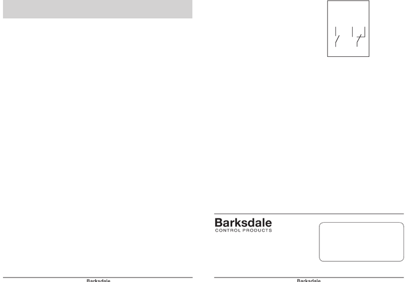
(NO) (SPDT)
Wiring diagram
23 2
11
2. Standard wiring diagram for switches,
provided with connector:
3. Adjusting the switching points
The switchpoint should be adjusted on the scale of the flowswitch. Please notice that the
switch point is always the shutdown point. That means the contact will open when the flow-
rate is decreasing to the adjusted switchpoint. So the NO opens in case of an alarm.
To adjust the switching contacts an ohmmeter, continuity tester or similar tool is required.
(NO) connection: Pin 1 & 2, (SPDT) connection: Pin 1 & 3
Units without optical indication (N/L-models)
a) Loosen the lock screw of the switch contact.
b) Shift the switch contact until the arrow on the switch contact is in coincidence with the
desired flow rate value on the range.
c) Tighten the lock screw of the switch contact.
Units without optical indication (O-models)
1. Adjustment of the removed unit:
a) Shift the switch housing from the centre of the adjustment range to the input side,
until the contact closes.
b) Shift the piston with a non-magnetic tool (e. g. a pencil) until the needle shows the
desired flow rate (contact closed).
c) Shift the switch housing slowly to the output side until the contact just opens.
At this point locate the switch housing with the lock screws.
2. Adjustment of the mounted unit:
a) see 1. a)
b) Open supply until the needle shows the minimal flow rate desired.
(contact closed)
c) see 1. c)
4. Maintenance
The flowmeters are free of maintenance because of the few mechanical parts. For security
reason we advice to check the flowmeters from time to time.
