Barnstead International Maxi Mix Plus M63215 User manual

Maxi Mix Plus
Vortex Mixer
OPERATION MANUAL
AND PARTS LIST
Series 1271
Model # Voltage
M63215 120
M63210-33 230
M63214 100
LT1271X1 • 11/6/02

IMPORTANT INFORMATION
This manual contains important operating and safety information. You must carefully
read and understand the contents of this manual prior to the use of this equipment.
Safety Information ..............................................................................................................................................3
Alert Signals..................................................................................................................................................3
Warnings ......................................................................................................................................................3
Introduction..........................................................................................................................................................4
Intended Use ................................................................................................................................................4
General Usage..............................................................................................................................................4
Principles of Operation ................................................................................................................................4
Performance Characteristics and Specifications ................................................................................................5
Declaration of Conformity ............................................................................................................................6
Operation ............................................................................................................................................................7
Troubleshooting ..................................................................................................................................................8
Maintenance and Servicing ................................................................................................................................9
To Replace the Mode Switch and/or Power Switch: ....................................................................................9
To Replace Microswitch ................................................................................................................................9
To Replace Motor: ......................................................................................................................................10
To Replace Damper Springs:......................................................................................................................11
To Install Silicone Rubber Platform Accessory ..........................................................................................11
Replacement Parts List ....................................................................................................................................12
Ordering Procedures ........................................................................................................................................13
Exploded View ..................................................................................................................................................14
One Year Limited Warranty ..............................................................................................................................16
2
Table of Contents

Your Thermolyne Maxi Mix has been designed with func-
tion, reliability, and safety in mind. It is your responsibility
to install it in conformance with local electrical codes. For
safe operation, please pay attention to the alert signals
throughout the manual.
Warnings
To avoid electrical shock, always:
1. Use a properly grounded electrical outlet of cor-
rect voltage and current handling capacity.
2. Disconnect from the power supply before servic-
ing.
To avoid personal injury:
1. Do not use in the presence of flammable or
combustible materials; fire or explosion may
result. This device contains components which
may ignite such materials.
2. Refer servicing to qualified personnel.
3
Safety Information
Caution
Cautions alert you to a possibility of
damage to the equipment.
Warning
Warnings alert you to a possibility of
personal injury.
Note
Notes alert you to pertinent facts and
conditions.
Alert Signals

Intended Use
The Maxi Mix Plus is a general laboratory vortex mixer. It
is intended for applications where vortexing of single or
multiple tubes is required.
The unit consists of 1) a rubber mixing cup, 2) a silicone
rubber mixing platform complete with plate & screws
3) a two–position mode switch for touch-on or constant-on
operation. Model M63210-33 also includes a separate
ON/OFF lighted power switch.
General Usage
Do not use this product for anything other than its intend-
ed use.
Principles of Operation
The mixer incorporates a permanently lubricated motor to
drive the mixing head. A two-position mode switch
enables the mixer to be operated continuously or by
depression of the rubber mixing cup or mixing platform.
The mixer operates up to the speed of 3200 rpm (max.).
Suction cup feet are incorporated to prevent “walking.”
4
Introduction

Electrical Specifications
M63215 120 Volts, 40 Watts, 60 Hz
M63210-33 230 Volts, 40 Watts, 50 Hz
M63214 100 Volts, 45 Watts, 50/60 Hz
Overall Dimensions
Weight W H D
M63215 6 lbs., 10 oz 5” 6-1/4” 8”
M63210-33 6 lbs., 10 oz 5” 6-1/4” 8”
M63214 6 lbs., 10 oz 5” 6-1/4” 8”
Maximum Speed
M63215 3200 rpm
M63210-33 3200 rpm
M63214 3200 rpm
5
Performance Characteristics
and Specifications

6
PERFORMANCE CHARACTERISTICS AND SPECIFICATIONS
Declaration of Conformity
Barnstead International hereby declares under its sole responsi-
bility that this product conforms with the technical requirements
of the following standards (230 volt models only):
EMC: EN 61000-3-2 Limits for Harmonic Current Emissions
EN 61000-3-3 Limits for Voltage Fluctuations and
Flicker
EN 61326-1 Electrical Equipment for Measurement
Control, and Laboratory Use; Part I:
General Requirements
Safety: EN 61010-1 Safety Requirements for Electrical
Equipment for Measurement, Control
and Laboratory Use; Part I:
General Requirements
EN 61010-2-051Part II: Particular Requirements for
Laboratory Equipment for Mixing and
Stirring.
per the provisions of the Low Voltage Directive 73/23/EEC, as
amended by 93/68/EEC.
The authorized representative located within the European
Community is:
Electrothermal Engineering, Ltd.
419 Sutton Road
Southend On Sea
Essex SS2 5PH
United Kingdom
Copies of the Declaration of Conformity are available upon
request.
Environmental Conditions
Operating: 17°C - 27°C; 20% - 80% relative humidity,
non-condensing. Installation Category II
(overvoltage) in accordance with IEC 664. Pollution Degree 2 in
accordance with IEC 664.
Altitude limit: 2,000 meters.
Storage: -25°C - 65°C; 20% to 80% relative humidity.

Place unit on a stable, flat surface and plug into an appro-
priate outlet.
The power switch on the M63215 and the M63214 is a
combination ON/OFF and mode switch to enable
“TOUCH” operation. Move the mode switch to either the
“CONSTANT ON” position or the “TOUCH ON” position.
In the “CONSTANT ON” position, the rubber mixing cup
will oscillate continually. In the “TOUCH ON” position, the
mixing cup will oscillate when pressure is applied to the
cup. To stop the mixing action, release the pressure being
exerted on the mixing cup.
Model M63210-33 incorporates a mode switch to enable
“TOUCH ON” or “CONSTANT ON” operation. This model
also includes a separate lighted ON/OFF switch.
7
Operation
Warning
To avoid electrical shock, use with a
properly grounded electrical outlet of
correct voltage and current handling
capacity.
To avoid personal injury, do not use in
the presence of flammable or com-
bustible chemicals; fire or explosion
may result. This device contains com-
ponents which may ignite such materi-
als.
The Troubleshooting section is intended to aid in defining and correcting possible service problems. When
using the chart select the problem category that resembles the malfunction, then proceed to the possible
causes category and take necessary corrective action.
Problem Possible Causes Corrective Action
Mixer does not operate Not connected to power supply. Check mixer connections to power
when mode switch is in supply.
the “Full On” position.
Defective mode switch. Replace mode switch.
Defective motor. Replace motor.
Mixer does not operate Not connected to power supply. Check mixer connections to power
when mode switch is in the supply.
“Touch On” position and
the mixing cup is depressed. Defective microswitch Replace microswitch.
Defective mode switch. Replace mode switch.
Defective motor. Replace motor.
Mixer does not operate Not connected to power supply. Check mixer connections to power
when power switch is supply
In either “On” position
(* M63210-33 only) Defective power switch. Replace power switch.
Defective mode switch. Replace mode switch.
Defective motor. Replace motor.
Internal chattering noise. Defective spring damper links. Replace spring damper links.
8
Troubleshooting
Warning
To avoid electrical shock, always dis-
connect from power supply before
servicing. Refer servicing to qualified
personnel.

To Replace the Mode Switch
and/or Power Switch
1. Disconnect mixer from power supply.
2. While holding the rubber mixing cup securely, loosen
the screw holding the cup down and remove the cup
from the counterweight.
3. Turn mixer upside down and remove the four screws
securing case. Turn mixer upright and remove case.
4. Disconnect wires from switch. Identify or mark wires
disconnected to ensure proper placement and con-
nection when reinstalling.
5. Remove defective switch.
6. Install new switch with the number “3” terminal on
top. Install the wires as identified or marked in Step
4.
7. Reinstall case and secure with four screws.
8. While holding the rubber mixing cup securely,
secure mixing cup to counterweight with the hold
down screw.
9. Reconnect mixer to power supply.
To Replace Microswitch
1. Disconnect mixer from power supply.
2. While holding the rubber mixing cup securely, loosen
the screw holding the cup down and remove the cup
from the counterweight.
3. Turn mixer upside down and remove the four screws
securing case.
4. Turn mixer upright and remove case.
5. Remove four screws and nuts securing motor.
6. Position motor on its side.
7. Disconnect the two wires from microswitch and
remove microswitch from motor. Save the spring and
9
Maintenance and Servicing
Warning
To avoid electrical shock, always dis-
connect from power supply before
servicing. Refer servicing to qualified
personnel.

plunger from defective micro switch. Identify or mark
wires disconnected to ensure proper placement and
connection when reinstalling.
8. Insert spring and plunger into the shaft of the new
microswitch. Position microswitch on mounting studs
and secure with two screws. Reconnect the wires as
identified or marked in Step 7.
9. Reposition motor and secure with four screws and
nuts.
10. Reinstall case and secure with four screws.
11. While holding the rubber mixing cup securely, secure
mixing cup to counterweight with the hold down screw.
12. Reconnect mixer to power supply.
To Replace Motor
1. Disconnect mixer from power supply.
2. While holding the rubber mixing cup securely, loosen
the screw holding the cup down and remove the cup
from the counterweight.
3. Turn mixer upside down and remove the four screws
securing case.
4. Turn mixer upright and remove case.
5. Remove four screws and nuts securing motor.
6. Disconnect wires from motor. Identify or mark wires
disconnected to ensure proper placement and connec-
tion when reinstalling.
7. Remove the counterweight assembly, bracket and
damper springs from top of motor.
8. Remove the six mounting studs and the microswitch
assembly from bottom of motor.
9. Reinstall the components removed in Steps 7 and 8 to
the new motor.
10. Reconnect the wires as identified or marked in Step 6.
11. Reposition motor and secure with four screws.
10
MAINTENANCE AND SERVICING

12. Reinstall case and secure with four screws.
13. While holding the rubber mixing cup securely, secure
mixing cup to counterweight with the hold down screw.
14. Reconnect mixer to power supply.
To Replace Damper Springs
1. Disconnect mixer from power supply.
2. While holding the rubber mixing cup securely, loosen
the screw holding the cup down and remove the cup
from the counterweight.
3. Turn mixer upside down and remove the four screws
securing case.
4. Turn mixer upright and remove case.
5. Remove defective damper springs.
6. Install new damper springs.
7. Reinstall case and secure with four screws.
8. While holding the rubber mixing cup securely, secure
mixing cup to counterweight with the hold down screw.
9. Reconnect mixer to power supply.
To Install Silicone Rubber Platform
Accessory
1. Disconnect mixer from power supply.
2. While holding the rubber mixing cup securely, loosen
the screw holding the cup down and remove the cup
from the counterweight.
3. While holding to prevent spinning, screw the accesso-
ry plastic base into place.
4. Remove the paper back from the silicone rubber disc
and press the side with the adhesive onto the plastic
base.
5. Reconnect mixer to power supply. 11
MAINTENANCE AND SERVICING

Series 1271
Description Part No. Part No.
100-120 volt 230 volt
Brass Counterweight Assembly CW1254X1A CW1254X1A
Counterweight Spring (2 required) SPX47 SPX47
Motor MTX95 - 120V MTX96
MTX97 - 100V
Cord set CR1254X1-120V CR632X3
CR632X1-100V
Strain Relief included with cord-120V included with cord
SRX10-100V
PC Board Switch (under motor) SW690X1A SW690X1A
Mode Switch “constant touch” SWX108 SWX108
Power Switch none SWX138
Fuse (2 required) Type F, 250V, 1 Amp FZX59-120V FZX59
none-100V
Cup Foot (4 required) CPX3 CPX3
Standard top mixing cup CP376X1A CP376X1A
3.5” Rubber Mixing Platform AY632X1A AY632X1A
3.5” Replacement rubber pad PT376X2 PT376X2
Please refer to the Specification Plate for the complete model number, serial number, and series number
when requesting service, replacement parts or in any correspondence concerning this unit.
12
Replacement Parts

All parts listed herein may be ordered from the Barnstead
International dealer from whom you purchased this unit or
can be obtained promptly from the factory. When service
or replacement parts are needed we ask that you check
first with your dealer. If the dealer cannot handle your
request, then contact our Customer Service Department
at 563-556-2241 or 800-553-0039.
Prior to returning any materials to Barnstead International,
please contact our Customer Service Department for a
“Return Goods Authorization” number (RGA). Material
returned without a RGA number will be refused.
13
Ordering Procedures
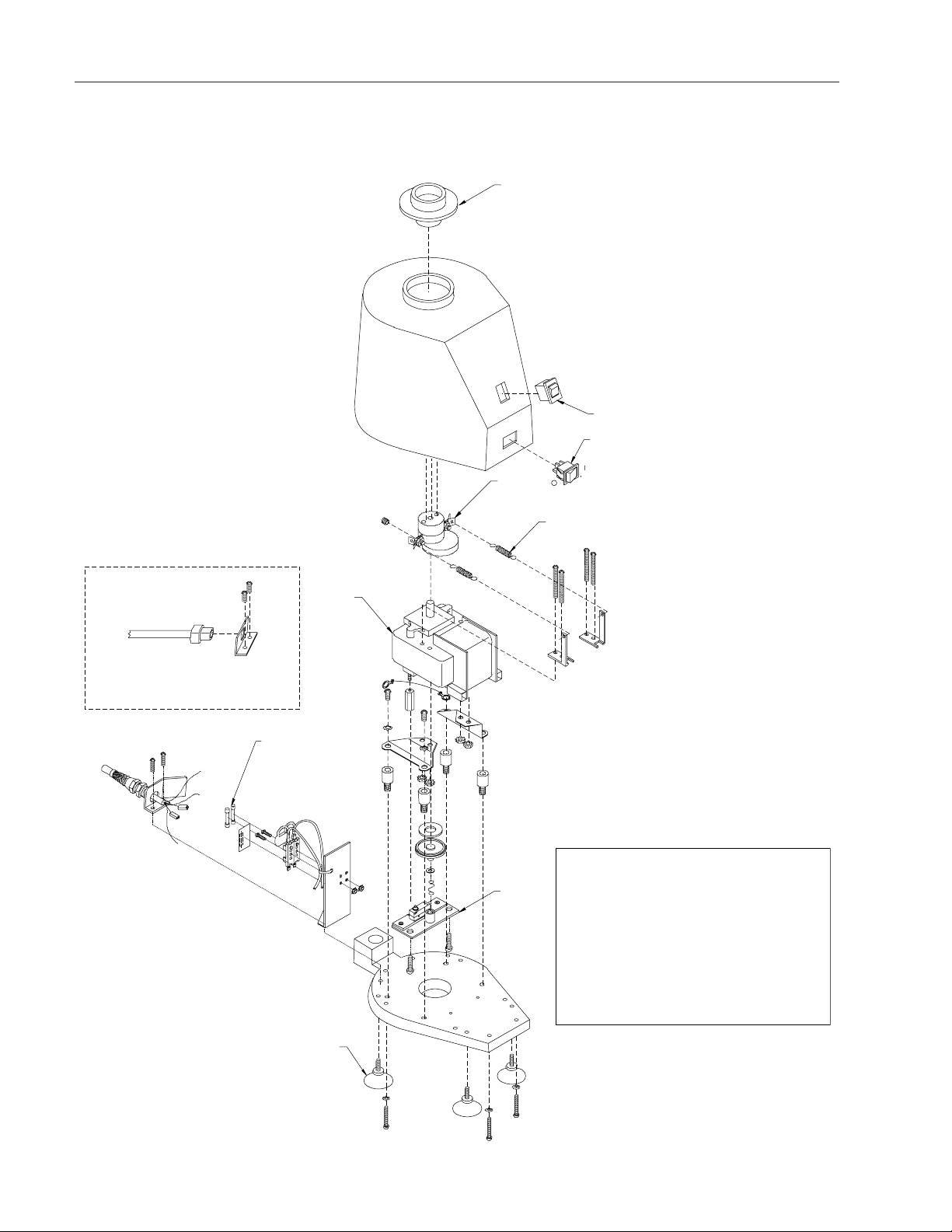
14
Exploded View
For 100 Volt Units
9
4
6
Key Description
1 Counterweight Assembly
2 Motor
3 Power Switch (230V only)
4 Switch Assembly
5 Mode Switch
6 Foot
7 Damper Springs
8 Rubber Cup Assembly
9 Fuse (120 & 230 Volt Only)
8
5
3
off
on
1
7
2

15

One Year Limited Warranty
BARNSTEAD INTERNATIONAL (“BARNSTEAD”) warrants that if a product manufactured by Barnstead shall
be free of defects in materials and workmanship for one (1) year from the first to occur of (i) the date the prod-
uct is sold by BARNSTEAD or (ii) the date the product is purchased by the original retail customer (the
“Commencement Date”). Except as expressly stated above, BARNSTEAD MAKES NO OTHER WARRANTY,
EXPRESSED OR IMPLIED, WITH RESPECT TO THE PRODUCTS AND EXPRESSLY DISCLAIMS ANY AND
ALL WARRANTIES, INCLUDING BUT NOT LIMITED TO, WARRANTIES OF DESIGN, MERCHANT ABILITY
AND FITNESS FOR A PARTICULAR PURPOSE.
An authorized representative of BARNSTEAD must perform all warranty inspections. In the event of a defect
covered by BARNSTEAD’s warranty, BARNSTEAD shall, as its sole obligation and exclusive remedy, provide
free replacement parts to remedy the defective product. In addition, for products sold by BARNSTEAD within
the continental United States or Canada, BARNSTEAD shall provide provide free labor to repair the products
with the replacement parts, but only for a period of ninety (90) days from the Commencement Date.
BARNSTEAD’s warranty provided hereunder shall be null and void and without further force or effect if there
is any (i) repair made to the product by a party other than BARNSTEAD or its duly authorized service repre-
sentative, (ii) misuse (including use inconsistent with written operating instructions for the product), mishan-
dling, contamination, overheating, modification or alteration of the product by any customer or third party or
(iii) use of replacement parts that are obtained from a party who is not an authorized dealer of BARNSTEAD.
Heating elements, because of their susceptibility to overheating and contamination, must be returned to the
BARNSTEAD factory and if, upon inspection, it is concluded that failure is due to factors other than excessive
high temperature or contamination, BARNSTEAD will provide warranty replacement. As a condition to the
return of any product, or any constituent part thereof, to BARNSTEAD’s factory, it shall be sent prepaid and a
prior written authorization from BARNSTEAD assigning a Return Goods Number to the product or part shall
be obtained.
IN NO EVENT SHALL BARNSTEAD BE LIABLE TO ANY PARTY FOR ANY DIRECT, INDIRECT, SPECIAL,
INCIDENTAL, OR CONSEQUENTIAL DAMAGES, OR FOR ANY DAMAGES RESULTING FROM LOSS OF
USE OR PROFITS, ANTICIPATED OR OTHERWISE, ARISING OUT OF OR IN CONNECTION WITH THE
SALE, USE OR PERFORMANCE OF ANY PRODUCTS, WHETHER SUCH CLAIM IS BASED ON CON-
TRACT, TORT (INCLUDING NEGLIGENCE), ANY THEORY OF STRICT LIABILITY OR REGULATORY
ACTION.
The name of the authorized Barnstead International dealer nearest you may be obtained by calling 1-800-446-
6060 (563-556-2241) or writing to:
2555 Kerper Boulevard
P.O. Box 797
Dubuque, Iowa 52001-0797
Phone: 563-556-2241 or 800-553-0039
Fax: 563-589-0516
E-mail: [email protected]
www.barnstead.com
This manual suits for next models
2
Table of contents
Other Barnstead International Mixer manuals

Popular Mixer manuals by other brands

Hamilton Beach
Hamilton Beach 840125800 user manual

Black & Decker
Black & Decker M275 Use and care book

Ninja
Ninja Ninja Master Prep QB1000 30 owner's guide

Protech Audio
Protech Audio 2000-C Installation & operation manual

WMF
WMF KULT X operating manual

KegLand
KegLand BucketBlaster KL15905 instruction manual

Goldair
Goldair GMX300 operating instructions

Electrolux
Electrolux Dito XBE80AS Brochure & specs

Cuisinart
Cuisinart SM-70 - Stand Mixer - SM-PM Pasta-Maker... Recipes

Scarlett
Scarlett SC-HM40S05 instruction manual

Tower Hobbies
Tower Hobbies T12039 Safety and instruction manual

P.Lindberg
P.Lindberg 9018936 Original instructions for use


