BARO BRC-4000 User manual

BARO SNT PRODUCT
MANUAL
www.barosnt.com
VER.1.0
2015/05/12
DIGITAL CONTROLLER
BRC-4000

CONTENTS
www.barosnt.com
Before Use:
Cautions and Warnings………………………………………………………3
Component Descriptions:
Front Panel Description……………..………………………………………. 4
Rear Panel Description……………………………………………………… 5
Control Pad Description:
Home Screen Description………..………………………………………….7
Projector & Motor Control Screen Description………………………….... 8
Motor Control Screen Description…………………………………………..8
E.Q. Control Screen Description………….………………………………...9
Lamp Control Screen Description…………………………………………..10
Connection:
Computer, Notebook Interface……………………………………………...11
Monitor, 7” Pad, Projector, Microphones..…………………………………12
Screen/Projector Elevation, Auxiliary.………………………………………13
Speakers……………………………………………………………………….13
Controller –Projector RS-232 Cable Connection…………………………14
Setup Procedures:
Basic Projector Protocol Input……....………………………………………15
Projector Protocol Input Procedure...……………………………………… 16
Controller Firmware Upgrade Procedure…….…………………………… 18
7” Pad Upgrade Procedure……………………………………………….. 19
Infrared Signal Programming……………………………………………..... 20
Factory Settings……………………………………………………………… 22
Full Specifications………………………………………………………………………………….24
2

3
www.barosnt.com
Cautions and Warnings:
•Never handle the product or power source with wet hands.
•Ensure the product never comes into contact with water or any other liquid. Ensure it is
installed in a location where liquid will not be poured on it. This may cause electrical
shock or fire.
•If liquid has entered the product, be sure to disconnect it from all power sources, inputs
and outputs, and contact your Baro representative for product inspection.
•Only use the power cable and components that were originally supplied with the product.
Substitutions may lead to injury or fire.
•Ensure the product is not installed where it will be operating in direct sunlight. This can
lead to product overheating, failure, and possibly fire.
•Ensure the product is disconnected from power sources during inclement weather. A
power surge may cause product damage.
•Ensure the product is installed in a well ventilated location to prevent overheating.
•Ensure the product is not installed near any flammable objects or gases.
•Ensure the product is installed in an area free from interfering wireless and radio
equipment for optimal performance.
•Do not place heavy objects on top of the product.
•Ensure the product is keep free of dirt, dust, and other objects that could potentially enter
it. This could cause product failure.
•Use common sense during the installation and use of this product to avoid any risks not
outlined in these warnings.
BEFORE USE

4
www.barosnt.com
Rear Panel Description
CONTROLLER LAYOUT
1.
IR1 / IR2
Infrared Control Outputs. Used
to
control connected devices with IR
control inputs.
IR1
–Output for IR control of connected device.
IR2
–Additional output for IR control of connected device.
2.
Tablet
Monitor
USB Ports
USB Ports for connection of Tablet
Monitor touch functionality. Used to
switch between the operating
computer and devices
connected to
the Notebook Interface.
TABLET
–Connect to your Tablet Monitor’s USB for Touch port.
PC
–Connect to an available USB port on your computer.
NOTE
–Connect to the USB port on Podium’s Notebook Interface.
3.
SENSOR
Sensor for integration of heating and
cooling systems.
SENSOR
–Use to connect to heating and cooling system thermostats. Control
temperature levels in facilities where integration is possible.
4.
AV Out
Composite
AV Output
AV OUT
–AV Output through composite connection:
Video Specifications :
Audio Specifications :
5.
AV IN1 / AV IN2
Component
and Composite video
inputs.
AV IN 1
–Component video input.
AV IN 2
–Composite video input.
6.
PROJECTOR
RS
-232 control for system projector.
Connect PROJECTOR to the RS
-
232 input of your projector to control its functions.
7.
KEYPAD
RS
-232 connection for controller
interface (7”LCD touch pad or 25 key
pad)
Connect KEYPAD to the RS
-232 input on the 7” LCD pad or the 25 Key pad to
operate the controller. This port is also used for conducting firmware upgrades.
8.
MONITOR OUT
VGA video
output for operating
computer monitor.
Connect MONITOR
OUT to your computer or podium’s monitor using a VGA cable.
Video Specifications :
9.
PC IN
VGA input for operating computer.
Connect PC IN to your operating computer. This will output your computer’s
screen to the connected video device (projector, display,
etc
) and podium monitor.
1 2 3 4 5 6 7 8 9
10 15 16 17 1811 12 13 14

5
www.barosnt.com
10.
SCREEN / ELE
Connection
port for projector screen
and projector elevation.
See connection
map on page ????? for full details.
11.
AUX1 / AUX2
Connection port for control of Auxiliary
1 and Auxiliary 2.
Auxiliaries
may be used to control facility functions such as lighting or heating and
cooling.
12.
L/R
SPEAKER
Output
connection port for left and
right speakers.
See connection map on page ????? for
full details. Ensure polarity and channels
are correct when making connections.
13.
MIC1 / MIC2
Input ports
for system microphones
Typically
these are the inputs for the podium’s gooseneck microphone and
wireless microphone system.
14.
PC / NOTE
Audio
Inputs for PC and Notebook
Interface connections.
PC
–3.5mm audio input for PC audio.
NOTE
–3.5mm audio input for Notebook audio.
15.
AUX
Additional RS
-
232 control for control of
auxiliary device.
Connect AUX to the RS
-232 input of another device to control its functions.
16.
RS232
RS
-232 input for programming
changes.
Connect your computer to this input for updating the controller’s protocols
.
17.
PROJECTOR
OUT
VGA video
output for video projector.
Connect PROJECTOR
OUT to your computer or podium’s monitor using a VGA
cable.
Video Specifications :
18.
NOTE IN
VGA video input for Notebook interface.
This video input will accept the video input signal from the podium’s laptop
interface.
NOTE:
The controller’s layout is designed according to use in Baro Digital Podiums. The inputs and
outputs can be programmed to different functions if customization is required. Contact us or
your product representative for more information.

6
www.barosnt.com
Front Panel Description
1.
Power
Physical switch for controller power.
Up
–System powered ON
Down
–System off.
2.
IR Sensor
Infrared
receiver for programming IR
signals into the controller.
Learn more about IR signal programming on page ???????.
3.
LED
Power Status Indicator
The red
LED light shows the status of the controller’s power and programming
status.
1 2
3

7
www.barosnt.com
7” Pad Home Screen Description:
1.
Lecture
Start / End
LECTURE START
–Automatically powers on projector, lowers projector and projector screen.
LECTURE END
–Automatically turns off projector, raises projector and projector screen.
2.
Input
Source
Select between operating the podium using the dedicated computer, or the device connected to the Notebook
Interface.
3.
Projector and Motor /
DVD/VCR
PROJECTOR & MOTOR
–Open a new screen showing the control options for the Projector, Projector Elevation
and Screen Elevation.
DVD/VCR
–Open a new screen showing options for alternative AV inputs and resources.
4.
Computer
Button to turn computer
power On or Off.
5.
Audio
Master output volume controls with quick mute
option.
6.
Mic 1 / Mic 2
Control options for microphone volume levels with quick mute options.
7.
E.Q.
Detailed option settings for audio
and volume.
1
3
2
4 5 6
7

8
www.barosnt.com
1.
Power
On / Off
Turn projector power on or off.
2.
Input
Source
Select between using
the podium’s computer as the video input source, or using another AV device.
3.
Mute (blank)
Controls
to blank the projector video output. This does not turn off the projector, but stops it from transmitting
any images while mute is in effect.
4.
Screen
Controls
Control the elevation
of the projector screen using Up, Stop, and Down buttons. The screen will automatically
stop once it reaches either its top or bottom limits.
5.
Elevation
Control the height of the projector. Use the Up, Stop and Down buttons to control the exact height of the
projector for systems with elevation motors. The projector motor will stop automatically once it reaches either its
top or bottom limits.
6.
IR
Input Controls
Opens a new screen to control various IR commands. IR functions vary by projector.
Review page ???? For
details on how to program IR inputs into you controller.
7.
Lamp Switch
Control for lighting systems.
8.
Projector
2
Opens an identical
screen for controls to manage a second projector and screen.
9.
Main
Return to the main
screen.
1
2 3 4 5
76 8 9
Projector & Motor Control Screen Description:

9
www.barosnt.com
1.
Volume Reset
Reset all custom volume settings to their factory
presets.
2.
Mic 1
HIGHT / LOW
–Control tonal settings for Mic1’s output.
3.
Audio
HIGH
/ LOW –Control tonal settings for the system’s overall audio output.
4.
Mic 2
HIGH / LOW
–Control tonal settings for Mic2’s output.
5.
Main
Return to the main
screen.
2
3
E.Q. Control Screen Description:
4
1 5

10
www.barosnt.com
1.
All On
Pressing this
button will turn On all lighting controlled by the system.
2.
All Off
Pressing
this button will turn Off all lighting controlled by the system.
3.
Power
-Saving
Initiates Lighting System’s power saving mode.
4.
Light 1~12
Control the On/Off status of each light individually.
5.
Main
Return to the main
screen.
4
1
Lamp Control Screen Description:
5
2 3

11
www.barosnt.com
PC, and Laptop Interface:
The following connection map is based on installation in a Baro Digital Podium.
CONNECTION
IR1 IR2 TABLET PC NOTE
AV OUT AV IN2
AV IN1
MIC1 MIC2 PC NOTE AUX RS232 NOTE IN
PROJECTOR
OUT
PROJECTOR KEYPAD PC INMONITOR
AVTABLET
USB
USB
AUDIO
VGA
LAPTOP INTERFACE
USB
USB
USB
USB VGA AUDIO
PC
SCREEN AUX1 / AUX2 L/R SP.

IR1 IR2 TABLET PC NOTE
AV OUT AV IN2
AV IN1
MIC1 MIC2 PC NOTE AUX RS232 NOTE IN
PROJECTOR
OUT
PROJECTOR KEYPAD PC INMONITOR
SCREEN AUX1 / AUX2 L/R SP.
12
www.barosnt.com
Tablet Monitor, 7” Pad, and Microphones:
The following connection map is based on installation in a Baro Digital Podium.
WIRELESS MIC RECEIVER
RANGE BALANCED
OUTPUT
UNBALANCED
OUTPUT

13
www.barosnt.com
Screen/Projector Elevation, Auxiliary:
UP COM DOWN UP COM DOWN 220V 220V
SCREEN ELEVATION PROJECTOR ELEVATION POWER
1 2 3 1 2 3
AUX 1 AUX 2
Speakers:
1 2 3 1
LEFT RIGHT
14
www.barosnt.com
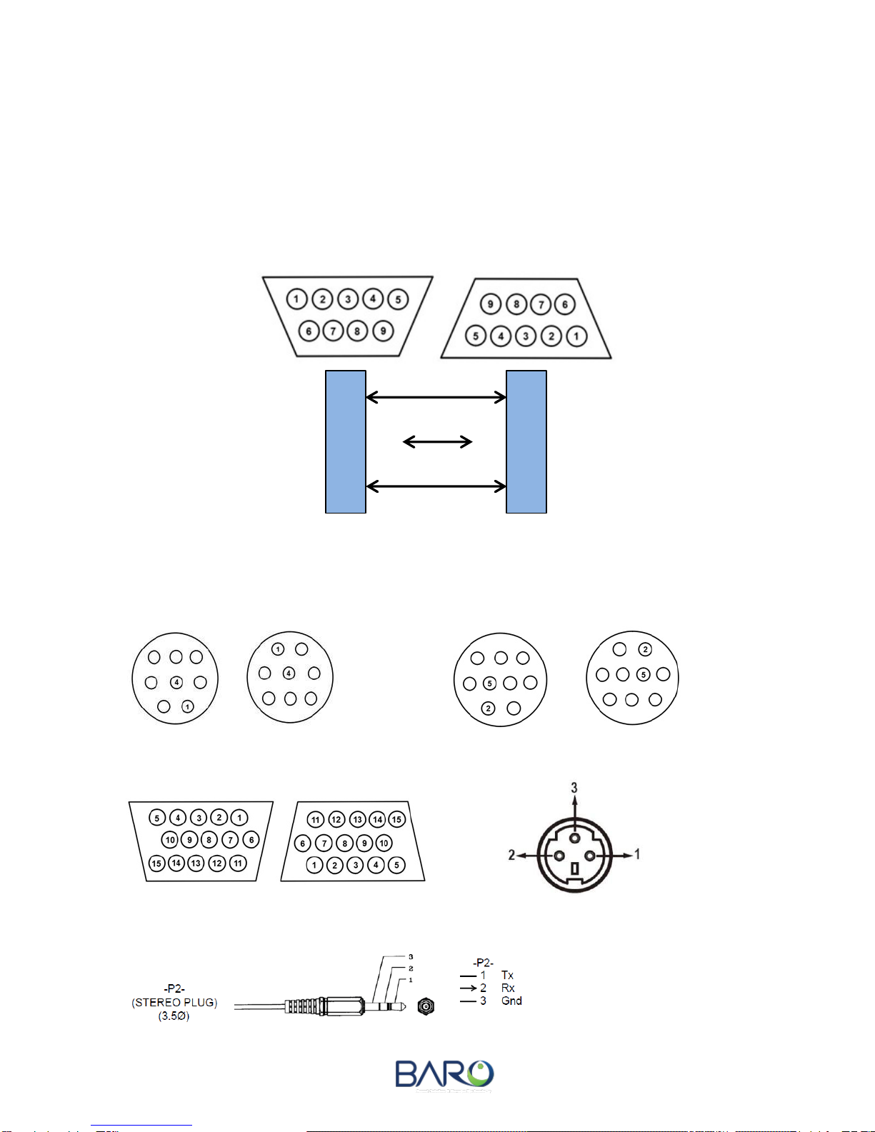
Projector –Controller RS-232 Cable Connection:
STANDARD 9 PIN D-SUB TYPE
*** When connecting the Controller to a Projector, Controller RX No.3 and Projector RX No.3 are
unused and should be terminated. This is common for most projectors, but when required by
specific projectors (Panasonic, BenQ) No.3 may be used.
RS-232 MINI DIN 8 PIN, 9 PIN / 15 PIN D-SUB / 3 PIN
8 Pin : RX 1 / GND 5 9 Pin : RX 2 / GND 5
15 Pin : RX 13 / GND 10 3 Pin : RX 2 / GND 2
3 Pin : RX 2 / GND 2
2
3
5
2
3
5
BRC-4000
Controller
Video
Projector
XX
TX
RX
GND
TX
RX
GND

15
www.barosnt.com
To connect your controller and projector, you must update the protocol. The following steps
outline a basic protocol input method using only 7” touch pad. If this method is unsucessful,
you will need to attempt the method found on page 16.
1. In the projector and motor screen, press the top left corner. This is a hidden button to
access projector protocol input.
2. In the screen that appears, select the brand of projector you are using. If it is not found
here, use the input method found on page 16.
1. Wait 7 seconds. Once complete, the controller will beep. To commit the changes, power
down the controller using the front power switch. Power the controller on and press the
Main button on the 7” Pad to return to exit the projector protocol input screen.
BASIC PROJECTOR PROTOCOL INPUT

16
www.barosnt.com
You will need to use a Windows based computer to conduct these changes. On the back of the
controller, disconnect the KEYPAD RS-232 cable. Connect this port to the computer you will
use to upgrade the protocol using an RS-232 cable.
***Before conducting protocol input, you should prepare your computer:
1. Install vbruntimes.exe.
2. Ensure that vb6ko.dll has installed in the windows “system32” folder. For 64 bit operating
systems the file should be located in the “syswow64” folder.
3. If this computer is used again to update protocol in the future, this process should not
need to be repeated.
Updating Projector Protocol:
1. Select the Com Port you are using to conduct the update by opening Windows Device
Manager. Press Start -> Control Panel -> System and Security. In the System and
Security submenu you will see Device Manager. Check that the RS-232 port is active. If
not, activate the port. Exit and open device manager again to ensure the changes were
committed.
2. With the computer connected to the controller, run the baro_input_ver1.exe file.
3. Select the open Com Port. Click the Start Input button (this will not begin any changes).
PROJECTOR PROTOCOL INPUT PROCEDURE

17
www.barosnt.com
4. Select the projector brand.
4. Click the “Power On” button and every other function button once. Clicking these buttons
commits the protocol changes in the controller. You should hear a beep emitted after
each button is clicked.
5. Once you have clicked and set each function button, you may repeat the process for
Projector 2 if there is one connected.
6. Following all inputs, turn OFF the controller using the power switch on its front plate.
Power the controller ON once more after a few second’s delay. This will save the
protocol changes and reboot the controller.
7. Disconnect the computer used to update the protocol and reconnect the podium control
pad’s RS-232 cable to the KEYPAD port. Turn off the computer’s Com Port.

18
www.barosnt.com
You will need to use a Windows based computer to conduct these changes. On the back of the
controller, disconnect the KEYPAD RS-232 cable. Connect this port to the computer you will
use to upgrade the protocol using an RS-232 cable.
***Before conducting protocol input, you should prepare your computer:
1. Ensure the controller is powered off.
2. After connecting the computer to the KEYPAD port by RS-232, turn the PROGRAM
switch so that it is set to the right side.
3. Select the Com Port you are using to conduct the update by opening Windows Device
Manager. Press Start -> Control Panel -> System and Security. In the System and
Security submenu you will see Device Manager. Check that the RS-232 port is active. If
not, activate the port. Exit and open device manager again to ensure the changes were
committed.
4. Power the controller ON and run STMicroelectronics flash loader to conduct the
upgrade. In the Flash Loader, select the connected port number in the “Port Name” drop
down menu. Press Next.
5. If a connection between the controller and computer is made, the light will appear green
and you may continue the update process by pressing Next. If a connection is not
available, the light will appear red. In this case, check the Com Port in Windows Device
Manager and ensure it is active. Press Next in the following window.
6. Select the file to load, and ensure that Global Erase and Optimize (Remove some FFs)
are selected. Press Next to continue.
7. A window will appear requesting the location of the .hex file. Find the relative file and
select Open. The upgrade will commence. Do not power off or disconnect the computer
and controller, or use any other programs while the upgrade is in process.
8. When the upgrade completes, press Close and power off the controller. Turn the
PROGRAM switch to the left to deactivate programming mode.
9. Disconnect the computer used to update the firmware and reconnect the podium control
pad’s RS-232 cable to the KEYPAD port. Turn off the computer’s Com Port.
10. Power on the controller. The controller should emit a beep sound, signalling the upgrade
was successful.
CONTROLLER FIRMWARE UPGRADE PROCEDURE

19
www.barosnt.com
You will need to use a Windows based computer to conduct these changes. On the back of the
controller, disconnect the KEYPAD RS-232 cable. Connect this port to the computer you will
use to upgrade the protocol using an RS-232 cable.
1. Remove the 7” pad’s power adaptor. Remove the SD card and format it.
2. Load the new file onto the SD card. Insert the SD card into the pad as shown in the
image below.
3. Reconnect the power adaptor and the update should commence automatically. The
update typically requires 3 minutes. After the update is complete, a screen similar to the
one shown in the picture below will appear.
4. Disconnect and reconnect the power adaptor. The pad should be ready for use with the
podium controller.
*** Never disconnect the power adaptor or SD card while an update is in progress. This can
seriously damage the pad’s internal memory.
7” PAD UPGRADE PROCEDURE

20
www.barosnt.com
***By default the BRC-4000 controller is formatted to operate projector power (ON/OFF), input selection,
and mute functions only. If you would like to control another device such as an interactive display or dvd
player, the controller will require an update so that the proper functions and interface can be utilized in
the 7” touch pad. For example, brightness, contrast, channel selection and other functions would need to
have icons custom programmed for control of a television or display. For IR programming of devices
other than projectors, contact your Baro representative to receive a customized controller interface.
For projectors and all other devices, the following process is used. The following example describes
programming a projector:
1. With the controller on, enter “Projector & Motor” as found on the main home screen.
2. Press “IR Input” in the bottom left of “Projector & Motor” screen.
INFRARED SIGNAL PROGRAMMING
Table of contents
Popular Control Unit manuals by other brands


Silex technology
Silex technology SX-550 Developer's reference guide

FAAC
FAAC 200MPS quick guide

Hirschmann
Hirschmann Dragon PTN Series user manual

Lovibond
Lovibond Tintometer PTV Series manual

Hays Fluid Controls
Hays Fluid Controls 2540 Series Installation, operation & maintenance instructions

Texas Instruments
Texas Instruments TPS40200 user guide

Burkert
Burkert 0420 operating instructions

EDAC
EDAC 320 user manual

TREND
TREND XCITE/BBC Installation and mounting instructions

Siemens
Siemens HOTEL SOLUTION HTC3.2 Series quick start guide

Aumuller
Aumuller SHEV EMB 8000+ Series Installation and commissioning instructions

ICPDAS
ICPDAS IR-712A user manual