INSTALLATION, OPERATION & MAINTENANCE INSTRUCTIONS
GENERAL INFORMATION
1. Clean the lines of all foreign material, (welding slag, pipe scale, dirt, thread chips etc.). Upstream
installation of a strainer may be necessary in dirty systems.
2. Air should be eliminated from the system prior to startup to assure quiet operation and freedom from water
hammer.
3. Hays Automatic Flow Control Valves may be installed in the pipe line horizontally, vertically or any angle
in between. Straight sections of pipe upstream or downstream of the Hays valve are unnecessary for proper
operation. Standard reducing bushings or flanges may be directly connected to the Hays valve if required.
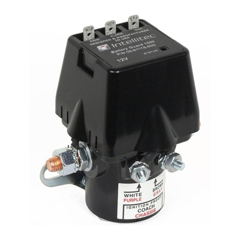
4. All Hays Automatic Flow Control Valves are marked with direction of flow and rate of flow.
THE FLOW ARROW MUST POINT IN THE DIRECTION OF FLOW FOR PROPER OPERATION.
5. Hays Flow Control Valves are factory assembled, individually calibrated and are tamperproof once
installed in the pipe. The valves are warranted to be accurate within 10% of rated flow when properly
installed.
6. Hays Automatic Flow Control Valves may be modified by using a Hays Service Kit. Contact Factory for
part numbers, instructions and other details.
OPERATION
1. For optimum operation, air entrainment in the system must be eliminated. The flow control valve must
remain filled with fluid. The system must be clean and free of foreign materials.
2. The Hays 2540 Mesurflo Valve must only be used with fluids that are compatible with, Iron, Brass, and
EPDM materials. The temperature during operation must be limited to the range of 32 F to 225 F.
3. The use of fluids having a specific gravity different from that of water will require adjustment. Valves
specified for fluids other than water will be so marked and the factory calibration will take the specific
fluid’s properties into consideration. Operation at a temperature other than the rated temperature may
require a correction.
INSTALLATION
1. Threaded valves are tapped with 2, 2 1/2, or 3 Inch NPT threads in accordance with ANSI Std B1.20.1
and are intended for use in Building Services Piping meeting the requirements of ASME B 31.9.
2. Apply thread sealant to male pipe threads, starting with the second or third thread from the end, and torque the
connection to 75 foot pounds per inch of pipe size minimum. Example: ( 3”, 3 X 75 = 225 ft lb. Min.) ( ¼”, ¼ X
75 = 19 ft lb. Min.)
3. Flanged valves are intended for use in Building Services Piping meeting the requirements of ASME B 31.9 and are
supplied with ANSI B16.5, 1968 , 150 lb. Raised face steel flanges. These flanges are to be connected into the
piping system utilizing new ASTM A194, GR 2H, nuts, new ASTM A193 GR B7 bolts, size 5/8 inch, and two
hardened steel washers under each nut.
4. Appropriate gasket material must be used when installing flange mounted flow control valves. The thinnest
practical gasket should be used whenever possible so as to optimize the joint performance.
2540 Series
Automatic Flow
Control Valves
ABV-IOM-2540-002-11 MAR 2013 Page 1 of 2
