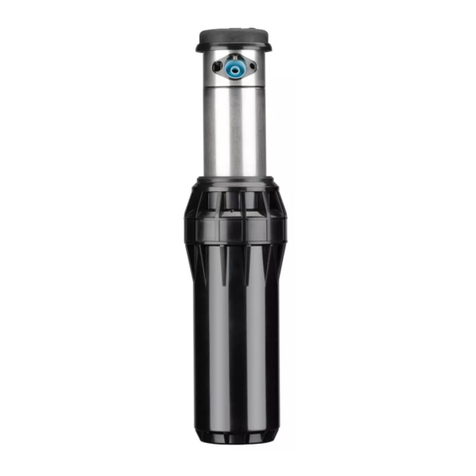
Hunter WVL-100 User manual

Wireless Valve Link
INSTALLATION GUIDE
WVL-100, -200, -400
Wireless Valve Link (WVL)

2
Get the WVL App
ESEN
FR
El Wireless Valve Link (WVL) permite el control
y monitoreo de electroválvulas sin necesidad de
cables para electroválvulas nuevas, existentes y
complementarias en sistemas de control ICC2 o HCC.
¡Obtenga la aplicación WVL para comenzar!
Le dispositif Wireless Valve Link permet de contrôler
et de surveiller sans l les électrovannes, et ce qu'elles
soient nouvelles, déjà installées, ou ajoutées en
complément dans les systèmes de contrôle
ICC2 ou HCC.
Téléchargez l'application WVL pour partir du
bon pied!
The Wireless Valve Link enables wire-free valve control
and monitoring for new, existing, and add-on valves in
ICC2 or HCC control systems.
Get the WVL App to get started!

3
Installation
EN
ES
FR
Install the Wireless Valve Output Module in any output
module slot in the controller and lock in place. The
module lights will ash. Push the Reset button on the
rear of the facepack.
Instale el módulo de salida de electroválvula
inalámbrico en cualquier ranura del módulo de salida
en el programador y fíjelo en su lugar. Las luces del
módulo parpadearán. Presione el botón «Reset»
(Restablecer) en la parte posterior de la carátula.
Installez le module de sortie pour électrovanne sans l
dans n'importe quel emplacement de module de sortie
du programmateur, puis verrouillez-le en place. Les
voyants du module clignotent. Appuyez sur le bouton
de reset situé à l'arrière de la façade.
RESET

4
Installation
EN
ES
FR
Open the battery cover on the Wireless Valve
Link. Unscrew the retaining ring, then remove the
waterproof cover.
Install one 9 V DC battery on the le side to allow easy
access to the button on the right.
Abra la tapa de la batería en el enlace de electroválvula
inalámbrico. Desenrosque el anillo de retención y luego
retire la tapa impermeable.
Instale una batería de 9 V CC en el lado izquierdo para
permitir un fácil acceso al botón de la derecha.
Ouvrez le couvercle des piles du dispositif Wireless
Valve Link. Dévissez l'anneau de retenue, puis retirez
le couvercle étanche.
Installez une pile 9Vc.c. du côté gauche pour faciliter
l'accès au bouton situé à droite.

5
EN
ES
FR
Hold down the right button closest to wires for 2
seconds to enter assignment mode. The light will
ash yellow.
Mantenga presionado el botón derecho, el más cercano
a los cables durante 2 segundos para activar al modo
de asignación. La luz parpadeará en amarillo.
Maintenez enfoncé pendant 2 secondes le bouton
droit le plus proche des ls pour passer en mode
d'attribution. Le voyant clignote en jaune.
EN
ES
FR
Connect the app to the Wireless Valve Output Module
in the controller. Use the app + button to assign the
station numbers and Save. The Wireless Valve Link
assignment light will ash and then turn o when
programming is successful.
Enlace con la aplicación el módulo de salida de
electroválvula inalámbrico situado en el programador.
Utilice el botón + de la aplicación para asignar los
números de estación y guardar. La luz de asignación
del Wireless Valve Link parpadeará y luego se apagará
cuando la programación sea haya guardado.
Connectez l'application au module de sortie
d'électrovanne sans l du programmateur. Utilisez le
bouton + de l'application pour attribuer les numéros
de station, puis enregistrez. Le voyant d'attribution du
dispositif Wireless Valve Link clignote, puis il s'éteint
lorsque la programmation a réussi.
Installation
2
3
4
3 , 4
3:25 PM 98%
Back
WVL MODEL
STATIONS
Station Number
Station Number
Add WVL 00352BBD
Save
DashboardSelect WVL Settings

6
EN
ES
FR
Install a second 9 V DC battery. Write the station
number on the Wireless Valve Link battery
compartment.
Reassemble the battery compartment. Push the cap
down rmly. Make sure the O-rings are not misaligned
and stay in their tracks. Then tighten the retaining ring
(hand-tighten only).
Instale una segunda batería de 9 V DC. Escriba el
número de estación en el compartimiento de la batería
del Wireless Valve Link.
Vuelva a montar el compartimento de la batería.
Empuje la tapa hacia abajo rmemente. Asegúrese
de que las juntas tóricas no estén desalineadas y que
permanezcan en sus guías. Luego apriete el anillo de
retención (apriete sin herramienta).
Installez une deuxième pile 9Vc.c. Notez le numéro
de la station sur le compartiment des piles du dispositif
Wireless Valve Link.
Remontez le compartiment des piles. Appuyez
fermement sur le couvercle. Assurez-vous que les
joints toriques sont bien centrés et qu'ils restent dans
leur logement. Serrez ensuite l'anneau de retenue
(à la main uniquement).
Installation

7
EN
ES
FR
Take the Wireless Valve Link to the valve box and
determine where it will be located. Make sure it won't
interfere with the valve, or install in its own valve box.
Final installation requires a minimum 4.25" (10.8 cm)
diameter and 6.25" (15.9 cm) vertical clearance below
the valve box lid.
La instalación nal requiere un mínimo de 4,25"
(10,8 cm) de diámetro y 6,25" (15,9 cm) de espacio
vertical debajo de la tapa de la arqueta.
Lleve el Wireless Valve Link a la caja de válvulas y
determine dónde se colocará. Asegúrese de que no
iroce con la electroválvula, o instálelo en una arqueta
independiente.
Amenez le dispositif Wireless Valve Link jusqu'au
regard d'électrovanne et déterminez l'endroit où il
sera placé. Assurez-vous qu'il n'interfère pas avec
l'électrovanne, ou installez-le dans son propre regard.
L'installation nale nécessite un diamètre minimum
de 4,25" (10,8cm) et un dégagement vertical de 6,25"
(15,9cm) sous le couvercle du regard d'électrovanne.
Installation
4.25" (10.8 cm)
6.25" (15.9 cm)

8
ES
FR
Mark the location for the hole in the valve box lid.
Use the hole saw supplied with the Wireless Valve
Output Module to drill a 1.5" (38 cm) hole through the
lid. A saw may be necessary to nish the cut through
the lid’s support ribs.
Insert the threaded column through the hole from
the bottom, and secure with the cap above. Tighten
supporting nut underneath.
Marque la ubicación del oricio en la tapa de la
arqueta. Utilice la sierra perforadora suministrada
con el módulo de salida de válvula inalámbrico para
perforar un oricio de 1,5" (3,8 cm) a través de la tapa.
Una sierra podría ser necesaria para terminar el corte a
través de las nervaduras de soporte de la tap.
Inserte la columna roscada a través del oricio desde
abajo y asegúrela con la tapa de arriba. Apriete la
tuerca de soporte que se encuentra debajo.
Marquez l'emplacement du trou dans le couvercle du
regard. Utilisez la scie cloche fournie avec le module
de sortie d'électrovanne sans l pour percer un trou de
1,5" (38cm) dans le couvercle. Une scie peut s'avérer
nécessaire pour terminer la découpe des nervures de
renfort du couvercle.
Insérez la colonne letée dans le trou par le bas, puis
xez-la avec le couvercle du dessus. Serrez l'écrou de
support en dessous.
EN
Installation

9
EN
ES
FR
Connect the numbered DC solenoid wires, red to red
and black to black. Use only waterproof connectors.
On multi-station versions, connect all black solenoid
wires together with the black common from the
Wireless Valve Link.
Conecte los cables numerados del solenoide DC,
rojo con rojo y negro con negro. Utilice solamente
conectores impermeables. En las versiones de
estaciones múltiples, conecte todos los cables
negros del solenoide junto con el común negro
del Wireless Valve Link.
Connectez les ls numérotés du solénoïde CC, rouge
à rouge et noir à noir. N'utilisez que des connections
étanches. Sur les versions à plusieurs stations,
connectez tous les ls de solénoïde noirs au l neutre
du dispositif Wireless Valve Link.
Installation

10
FCC Compliance Notice (FCC ID: M3UWVL)
This device complies with Part 15 of the FCC Rules. Operation is subject to the
following two conditions: (1) This device may not cause harmful interference,
and (2) this device must accept any interference received, including
interference that may cause undesired operation.
This equipment has been tested and found to comply with the limits for a Class
B digital device pursuant to Part 15 of the FCC Rules. These limits are designed
to provide reasonable protection against harmful interference in a residential
installation. This equipment generates, uses, and can radiate radio frequency
energy and, if not installed and used in accordance with the instructions, may
cause harmful interference to radio communications. However, there is no
guarantee that interference will not occur in a particular installation. If this
equipment does cause harmful interference to radio or television reception,
which can be determined by turning the equipment o and on, you are
encouraged to try to correct the interference by taking one or more of the
following measures:
• Reorient or relocate the receiving antenna.
• Increase the separation between the equipment and receiver.
• Connect the equipment into an outlet on a circuit dierent from that of
which the receiver is connected.
• Consult the dealer or an experienced radio/TV technician for help.
Changes or modications not expressly approved by Hunter Industries
could void the user’s authority to operate this device. If necessary, consult a
representative of Hunter Industries Inc. or an experienced radio/television
technician for additional suggestions.
This equipment complies with FCC radiation exposure limits set forth for an
uncontrolled environment. In order to avoid the possibility of exceeding the
FCC radio frequency exposure limits, human proximity to the antenna shall not
be less than 20cm during normal operation.
Innovation, Science, and Economic Development Canada (ISED)
Compliance Notice (IC: 2772A-WVL)
This device contains licence-exempt transmitter(s)/receiver(s) that comply
with Innovation, Science, and Economic Development Canada’s licence-exempt
RSS(s).
Operation is subject to the following two conditions:
1. This device may not cause interference, and
2. This device must accept any interference, including interference that may
cause undesired operation of the device.
Radiation Exposure Statement:
This equipment complies with ISED radiation exposure limits set forth for an
uncontrolled environment. This equipment should be installed and operated
with greater than 20cm between the radiator & your body.
Le présent appareil est conforme aux CNR d'Industrie Canada applicables
aux appareils radio exempts de licence. L'exploitation est autorisée aux deux
conditions suivantes :
1. L'appareil ne doit pas produire de brouillage, et
2. L'utilisateur de l'appareil doit accepter tout brouillage radioélectrique subi,
même si le brouillage est susceptible d'en compromettre le fonctionnement.
Déclaration d’exposition aux radiations:
Cet équipement est conforme aux limites d’exposition aux rayonnements ISED
établies pour un environnement non contrôlé. Cet équipement doit être installé
et utilisé à plus de 20 cm entre le radiateur et votre corps.
Notices
11
hunter.help/WVL
SCAN
for help
Troubleshooting
ES
FR
Para obtener información completa sobre operaciones
y solución de problemas, visite las páginas de soporte
de Hunter.
Pour des informations complètes sur le fonctionnement
et le dépannage, consultez les pages d'assistance
de Hunter.
EN For complete operations and troubleshooting
information, visit the Hunter Support pages.

HUNTER INDUSTRIES | Built on Innovation®
1940 Diamond Street, San Marcos, CA 92078 USA
hunterindustries.com
© 2023 Hunter Industries Inc. Hunter, the Hunter logo, and other
marks are trademarks of Hunter Industries Inc., registered in the
U.S. and certain other countries.
RC-184 IG MULTI 10/23
This manual suits for next models
2
Table of contents
Other Hunter Control Unit manuals

Hunter
Hunter I-40 User manual

Hunter
Hunter Hydrawise WAND User manual

Hunter
Hunter A2C-LAN User manual

Hunter
Hunter WVOM User manual

Hunter
Hunter CELL-KIT User manual

Hunter
Hunter HYDRAWISE X2 User manual

Hunter
Hunter A2C-LTE User manual

Hunter
Hunter DUAL 48M Operating instructions

Hunter
Hunter Hydrawise WAND User manual

Hunter
Hunter ACC-COM-LTE User manual