Barox PD-BTPMC102M-GE User manual

User Manual: PD-BTPMC102M-GE
Industrial Media converter lite managed with PoE af/at/bt
Version 3.2021

Page 2/13
Introduction
The Lite Managed Industrial GbE Fiber-to-Ethernet 802.3bt PoE media converter PD-BTPMC102M-GE
is equipped with 2-port 10/100/1000 Base-TX IEEE 802.3bt PoE standard to transmit data and power
between 1000 Base-FX Fiber and 10/100/1000BASE-T(X) Ethernet interface.
The PD-BTPMC102M-GE delivers up to 120 watts of power output to PDs. With ultra-compact
hardened design and dual DC power inputs, the PD-BTPMC102M-GE offer power protection for
redundancy and operate in extremely harsh conditions.
Featuring an extended operating temperature range of -40 to 75C, the PD-BTPMC102M-GE come with
efficient web-based management interface to help quickly evaluate the PoE status and the power
usage in hazardous environments as well as to flexibly configure the PoE output budget at remote site.
The PD-BTPMC102M-GE also provides an optional entry-level central network management software
(ISMS One), which includes dashboards, configuration settings, and MQTT publish, allowing the
administrator to manage centrally for easily deploying, controlling and monitoring.
Supporting Link Fault Pass-Through (LFPT) function via DIP switch setting, the PD-BTPMC102M-GE
enables the uplink device to get the failed link information if the downlink device fails. Built-in relay
output warning, the PD-BTPMC102M-GE prevents damage and loss from power failure and port link
down. The Lite Managed Industrial GbE Fiber-to-Ethernet 802.3bt PoE media converter PD-
BTPMC102M-GE enable reliable high data transmission speed and stable long distance network
communication in a variety of industrial environments.
Features
⚫2-Port 10/100/1000 Base-TX RJ45 IEEE 802.3bt
⚫Deliver up to 90W/120W of Power Output (Managed Power).
⚫Terminal block and DC Jack for redundant DC power inputs.
⚫-40 to 75°C operating temperature range.
⚫Support Link Fault Pass-Through (LFPT).
⚫Built-in relay output warning for power failure and port link down.
⚫Provide easy-to-use web management functions.
Page 3/13
Power connection
The PoE injector provides dual DC power input for redundancy. Each power input voltage depends on
the situation of power budget to select the voltage range.
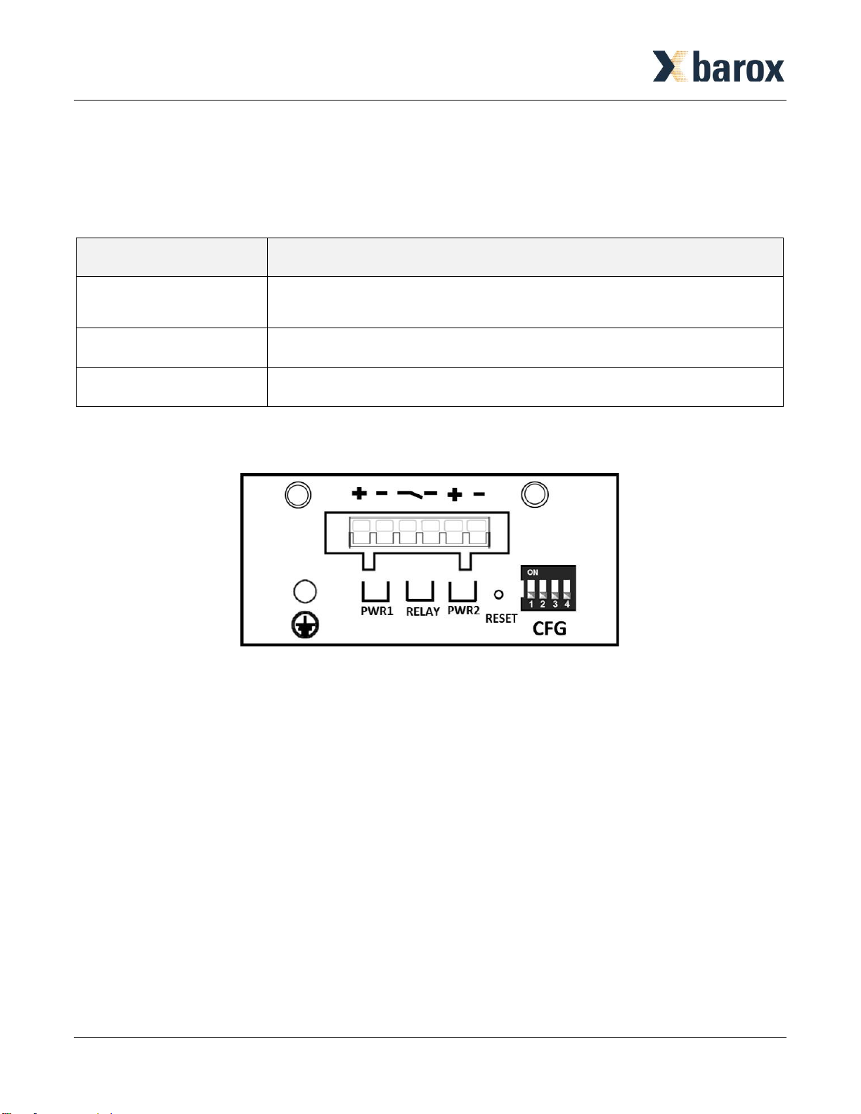
Hardware Description
On the top panel the following interfaces are placed:
⚫Wiring the Alarm Contact.
⚫Wiring the Power Inputs.
⚫DIP Switch Setting.
⚫Reset Configuration.
⚫Grounding Connection.
Model Name
PD-BTPMC102M-GE
LAN Interface
2 ports
10/100/1000 Base-TX
Power Budget
120 Watts
Voltage Range
48V(3A) ~ 56V(2.5A)
Page 4/13
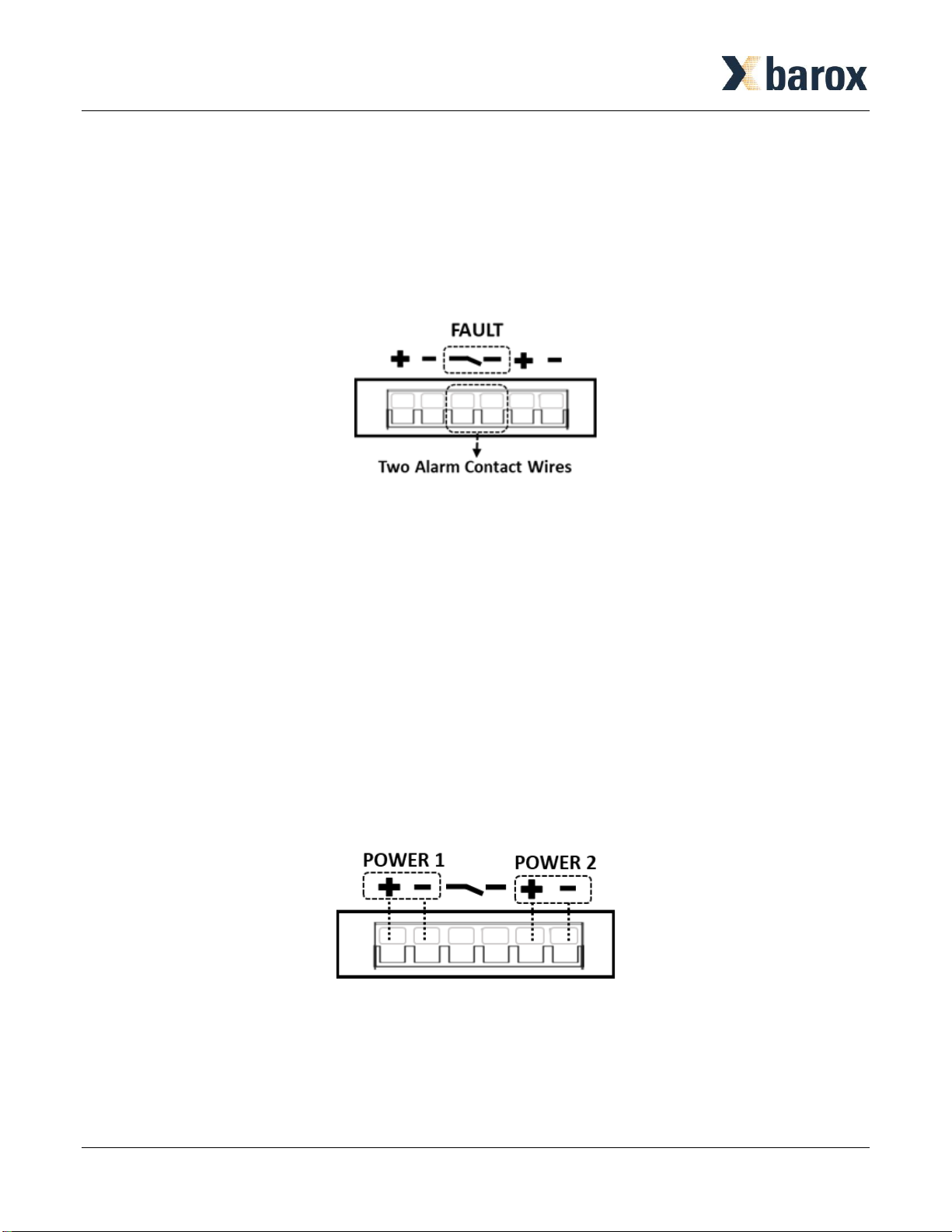
Wiring the Alarm Contact
The alarm contact wires are at the two middle contacts of the 6-contact terminal block connector. The
two wires attached to the fault contacts form an open circuit when detecting the fault status of the
power failure or the Ethernet port link fails.
*Note: Only use cooper conductors. (12~24 AWG wire gauge, 5.2kgf-cm (MAX) torque.)
Wiring the Power Inputs
The power contact wires at the two right and two left sides of the 6-contact terminal block connector are
used for two DC Inputs.
STEP 1: Insert the positive/negative DC wires into to the V+/V- terminals for power 1 and power 2.
STEP 2: Tighten the wire-clamp screws for avoiding the DC wires loosening by using a small flat-blade
screwdriver.
*Note:
▪Please check the DC power source voltage is stable before connecting.
▪Only use cooper conductors. (12~20 AWG wire gauge, 5.2kgf-cm (MAX) torque.)

Page 5/13
Installation Procedures DIN RAIL
Mounting Step
STEP 1: Hook the unit over the DIN Rail.
STEP 2: Push the bottom of the unit towards the DIN Rail until it snaps into place.
Removal Step
STEP 1: Push the unit down to free the bottom of the DIN Rail.
STEP 2: Rotate the bottom of the unit away from the DIN Rail.
STEP 3: Unhook top of unit from DIN Rail.

Page 6/13
LED Definition
The function of each LED indicator on the front panel is described in the table below.
LED
Color
State
Description
PWR1
Green
ON
Power is provided from power input 1.
PWR2
Green
ON
Power is provided from power input 2.
SYS
Green
ON
System is working.
ALARM
Red
ON
Alarm happens.
PoE1
Green
ON
Power output is on port 1.
PoE2
Green
ON
Power output is on port 2.
SFP 1000
Green
ON
SFP is at 1000Mbps.
SFP 100
Green
ON
SFP is at 100Mbps.
LAN 1000
Green
ON
Link speed is at 1000Mbps.
Green
Blinking
Data is transmitting.
LAN 10/100
Yellow
ON
Link speed is at 10/100Mbps.
Yellow
Blinking
Data is transmitting.

Page 7/13
DIP Switch Configuration
There are four settings for DIP switch, including Relay, LFPT, PoE, and SFP. The configuration of DIP
switch is described in the table below.
DIP
Mode
ON
OFF
1
Relay
•The hardware device is set to ON mode, and
Alarm Relay Output is enabled. If using web
page to control Alarm Output and the mode is
set to ON, Alarm Relay Output can be set to
enable or disable in web page.
•If the device power is failure or the Ethernet port
link fails, the relay activates alarm and the fault
LED lights up. Relay contact is normally close.
•Disable Alarm Output.
2
LFPT
•The hardware device is set to ON mode, and
LFPT function is enabled. If using web page to
control LFPT function and the mode is set to ON,
LFPT function can be set to enable or disable in
web page.
•The function is to pass link failure alarm to the
downstream device when the upstream device
has link failure alarm.
•Disable LFPT
•(Link Fault Pass-through).
3
PoE
•The hardware device is set to ON mode, and
PoE Output is enabled. If using web page to
control PoE Output and the mode is set to ON,
PoE output function can be set to enable or
disable in web page.
•Disable PoE Output.
4
SFP
•Use web page to control SFP mode. (Support
1000M/100M only.)
•Force SFP port to 1000M.
*Note: There are four white buttons for DIP switch. Moving the white button
up position, its setting is “ON”. Moving the white button down
position, its setting is “OFF”.

Page 8/13
Access the Web Configurator
After properly connecting the hardware as previously explained. Launch your web browser and enter
http://192.168.1.1 as URL. The default IP address, username, and password are as follows.
⚫Default IP Address: 192.168.1.1
⚫Default Username: admin
⚫Default Password: 2wsx#EDC
Please fill in the default username admin and the default password 2wsx#EDC, and then click Login.
For the system security, changing the default password is strongly suggested after configuration. You
can go to the User setting to reset.
*Note:
•The device only supports one web session.
•The timeout of web session is 15 minutes.
The system information is shown as below. This section includes Hardware MCSV, Software MCSV,
Software Version, PSE Software Version, MAC Address, Serial Number, Current Time, and System Up
Time.
Page 9/13
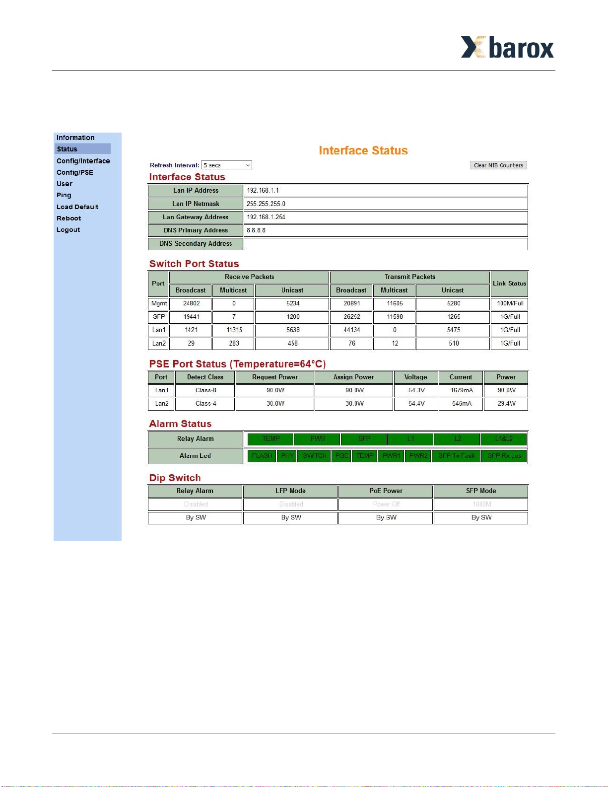
The system status is shown as below. This section includes Switch Port Status, PSE Port Status, Alarm
Status, and DIP Switch.
Page 10/13
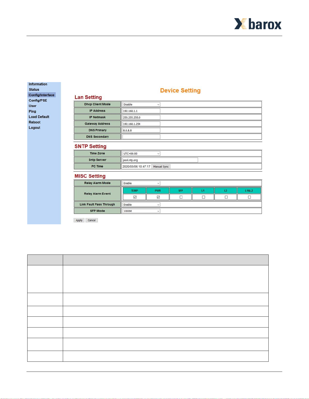
The device setting is shown as below. This section includes LAN Setting, SNTP Setting, and MISC
Setting.
⚫The SNTP server is necessary when PoE scheduling mode is on.
⚫The situation of Relay Alarm Event is described in the table below.
Item
Description
Temp
▪When the temperature is over 110 degrees C, the relay alarm event is enabled.
▪The relay alarm event will return to the normal status when the temperature
is small than 100 degrees C.
PWR
When the power is failure from Power Input 1 or Power Input 2, the relay alarm
event is on.
SFP
When SFP link is disconnected, the relay alarm event is on.
L1
When the Ethernet link from port 1 is disconnected, the relay alarm event is on.
L2
When the Ethernet link from port 2 is disconnected, the relay alarm event is on.
L1&L2
When the Ethernet links from both port 1 and port 2 are disconnected, the relay
alarm event is on.

Page 11/13
The PSE configuration is shown as below. This section includes Port Link Speed, and PSE Setting.
For the PSE Setting, there are some principles to describe in the table below.
Item
Description
Power Budget
▪The total maximum power budget is 120W.
▪The valid power budget is as follows.
LAN 1
LAN2
30W
90W
60W
60W
90W
30W
Keep Alive
Enable
When the mode is enabled, the device will have the following status.
▪Step1: Power on device and wait 90 seconds.
▪Step2: When Ethernet link is connected, the device will send the ping
request every 15 seconds.
▪Step3: When the ping response is received, reset the ping counter and
go to Step2. Otherwise, increase the ping counter.
▪Step4: When the ping counter is over three times, cut off the port power.
▪Step5: Wait 30 seconds, then the power is on the port and go to Step1.
Keep Alive IP
Address
Keep Alive IP is the IP of device connected to the port.
This section allows you to set up and change your username and password for different level users.
The users setting is shown in the interface as below.
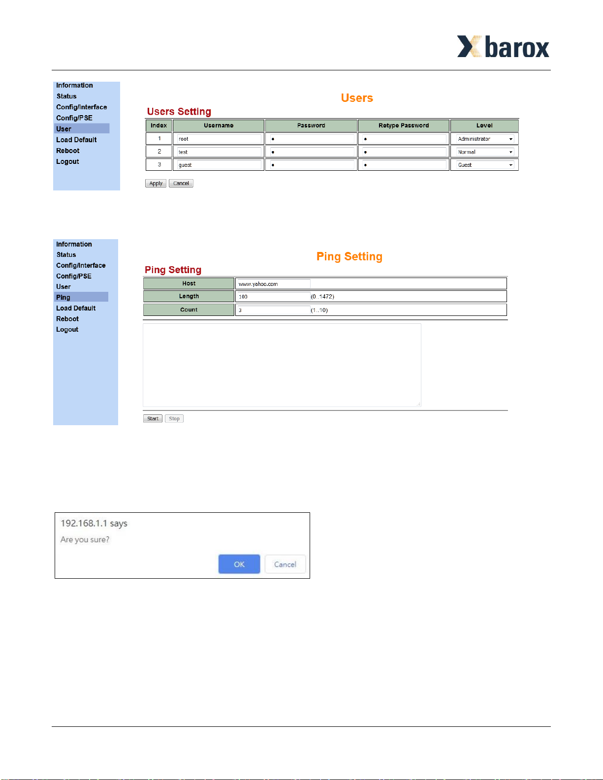
Page 12/13
The Ping Setting is shown in the interface as below.
Reload the device default configuration.
After clicking Load Default item, it will be shown the interface as below to make sure if you are ready to
load or not.
Reboot the device.
After clicking Reboot item, it will be shown the interface as below to make sure if you are ready to
reboot or not.

Page 13/13
Precautions and Safety Warnings
●Disconnect all power from devices before attempting installation.
●This device is intended for installation only in restricted access locations as defined where
both these conditions apply:
▪Access is through the use of a lock or tool and key, or other means of security, and is
controlled by the authority responsible for the location.
▪Access can only be gained by service persons or by users who have been instructed about
the reasons for the restrictions applied to the location and about any precautions that shall
be taken.
●All electric installations must be carried out in accordance with local and national regulations.
●Do not work on the system, connect or disconnect cables during periods of lightning activity.
●The equipment must be connected to earth.
●Shield of RJ45 cables has to be connected to the same earth potential as the equipment.
Hot parts!
●Burned fingers when handing the parts.
●Wait one-half hour after switching off before handing parts.
Table of contents
Popular Media Converter manuals by other brands


Littfinski Daten Technik
Littfinski Daten Technik S-DEC-4-MM-B Assembly instruction

Axis
Axis M7001 installation guide

Extron electronics
Extron electronics SDI to Analog Video Converter SDI-AVR 100 Specifications

SICK
SICK DGS66 installation instructions

Safe Fleet
Safe Fleet GPS Series Quick installation guide

Omron
Omron CK3M-CPU1 1 Series Startup guide