Huidu Technology HDP501 User manual

http://www.huidu.cn/ 1
User manual
Video processor HDP501
V1.220180126

http://www.huidu.cn/ 2
Safety instructions
This symbol prompts the user that there is important operating and maintenance instructions
in this device user manual.
This symbol warns the user that there is an exposed dangerous voltage inside the device's
chassis and that there is a danger of electric shock.
Note
READER • Users must read and understand all safety and operating instructions before using this
equipment.
SAVE INSTRUCTIONS • The user should save the safety instructions for future use.
Follow the warnings • The user should follow all safety and operating instructions in the product
and user's guide.
Avoid adding • Do not use tools or extra equipment not recommended by the manufacturer to
avoid any danger.
Warning
Power • Use only the power indicated on the product with this device. The equipment must be
powered by a power supply system that has a ground wire. The third line (ground) is a safety
device that can not be unused or skipped.
Unplug the Power • To unplug the power cord from the device safely, unplug all equipment or the
desktop power cord, or any power cord connected to the mains.
Power Line Protection • Route properly to avoid being walked on or heavy objects squeezed.
Maintenance • All repairs must be performed by a certified service technician. There are no user-
replaceable parts inside the equipment. To avoid the risk of electric shock Do not attempt to open
the device cover yourself to service the device.
Ventilation holes • Some equipment enclosures have ventilation slots or holes in them to prevent
overheating of in-plane sensitive components. Do not block the vents with anything.

http://www.huidu.cn/ 3
Contents
Chapter I Overview ........................................................................................................................4
1. Features..............................................................................................................................4
Chapter II panel..............................................................................................................................6
1.Rear panel............................................................................................................................6
2.Front panel...........................................................................................................................6
Chapter III Menu system...............................................................................................................9
1. Navigation mode................................................................................................................9
2.The main menu..................................................................................................................10
3.Output resolution...............................................................................................................10
4. Screen parameters..........................................................................................................11
5. Intercept parameters.......................................................................................................12
6. Save mode........................................................................................................................12
7. Mode call...........................................................................................................................13
9. Brightness contrast..........................................................................................................14
10. Output settings...............................................................................................................14
11. Version Information........................................................................................................14
12. System restart................................................................................................................15
13. Factory settings..............................................................................................................15
14. Mode delete....................................................................................................................15
15.Key lock............................................................................................................................16
Chapter IV Key Settings..............................................................................................................16

http://www.huidu.cn/ 4
Chapter I Overview
LED video processor is a mid-end seamless effects switching video processor market,
which supports digital high-definition input, analog high-definition input, analog SD input,
audio input, enabling all channels of audio and video synchronization seamless
switching.
Listed below LED video processor supports audio and video input format table:
DVI input support VESA standard, highest up to 1920x1200@60Hz
HDMI input 480i/p 676i/p 720p 1080i/p color depth 8/10/12 bit.
VGA input support VESAstandard,highest up to 1920x1200@60Hz
Composite video input PAL、NTSC、PAL-M/N、SECAM
Output format:
DVI output any resolution up to 1920 × 1200 @ 60Hz or 1440 × 1600 @ 60Hz
Custom resolution output.
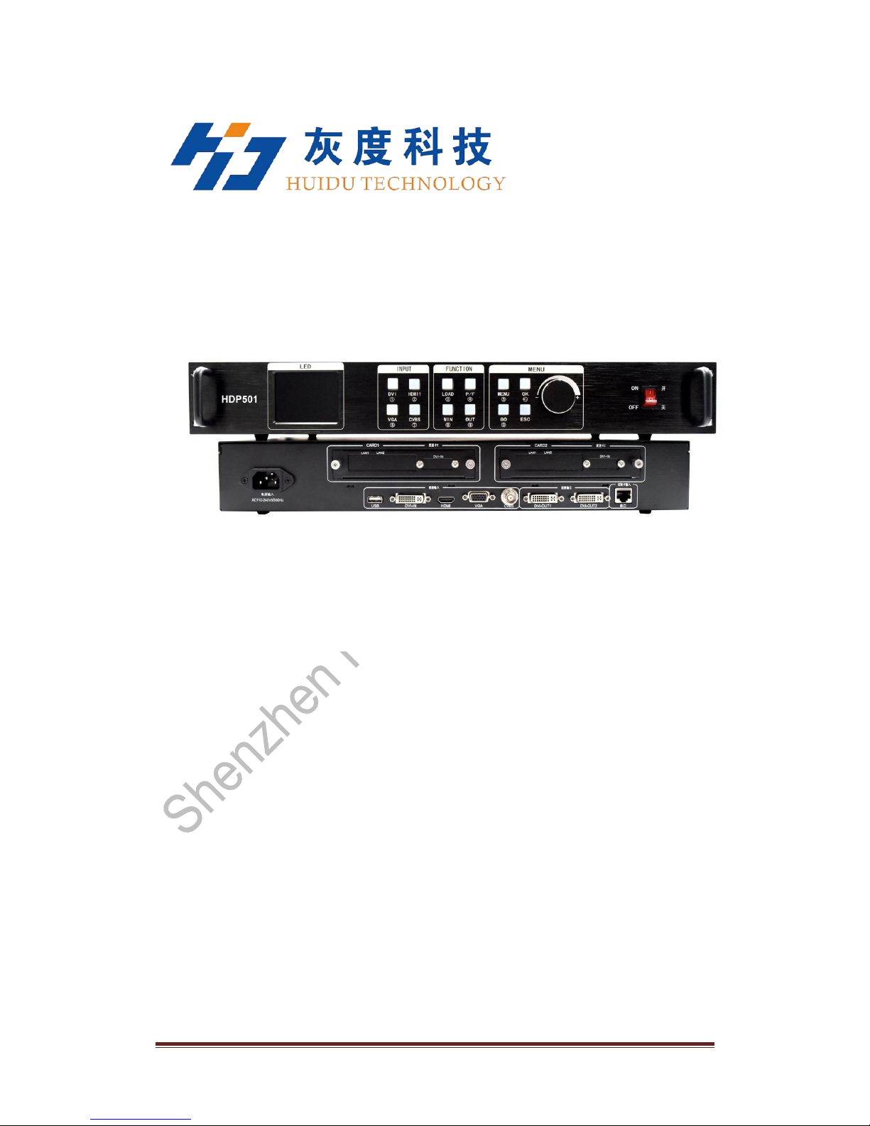
1. Features
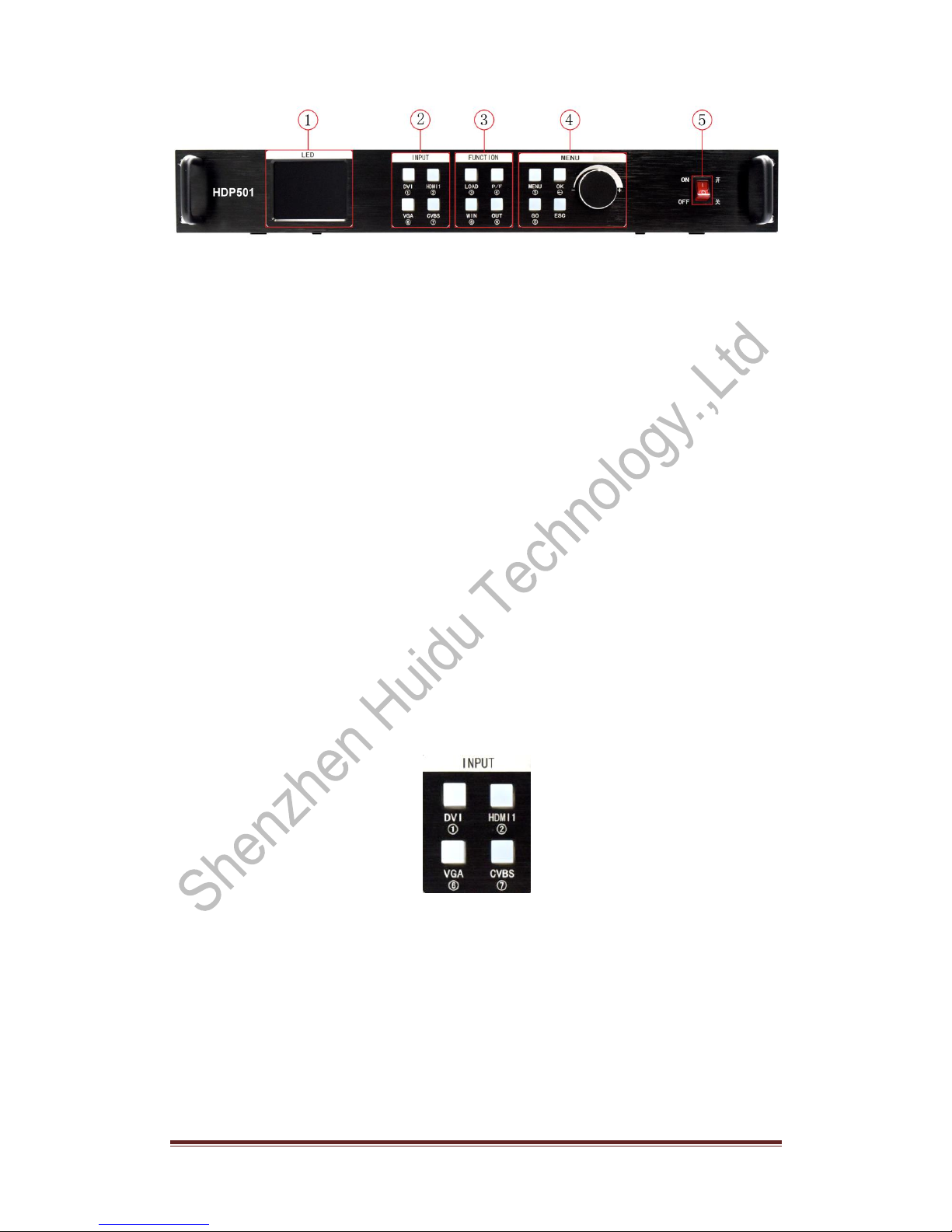
Multi-channel video input - Video processor with 5 video inputs, including 1 CVBS and
1 VGA, 1 DVI, 1 HDMI, 1 USB. Basically already covers the needs of civil and industrial
use. All video input switch and can achieve fast cut and fade switch effect.
Practical video output interface - The processor has 2 programmable video outputs.
With 2 DVI output interface. These two videos are programmed to be output to the LED
sending card or display.
Seamless switching between arbitrary channels - Video processor The video
processor can also be seamlessly switched between any channel, the switching time
from 0 to 1.5 seconds adjustable. Use the fade transition effect, when switching the input
channel, you can make the screen smooth switch to the second screen. Use fast
switching, switching input channels, you can instantly switch the video output.
Rich output resolution - video processor designed for the user a number of practical
output resolution, the most up to 1920 points, up to 1600 points, for a variety of dot matrix
display. Up to 20 kinds of output resolution for the user to choose, and can be adjusted to
the point-to-point output. At the same time, users can also use the custom resolution
output, to meet the various size display.
Support pre-switching technology - Pre-switching technology, is to switch the input
signal, the predicted channel is switched in advance whether there is a signal. This
feature reduces the possibility of direct errors due to line disconnection or no signal input,
resulting in an increase in the success rate of the performance.
Support a key black screen - black screen in the performance process is an essential
operation, during the performance process, you need to turn off the image output, you
can use the black screen to achieve fast black screen.
Support screen freeze - During playback, it may be necessary to freeze the current
screen to achieve "pause" screen. When the screen is frozen, the operator can also
change the current input selection or change the line, etc., to avoid background effects
affect the performance.

http://www.huidu.cn/ 5
Part and full screen fast switching - video processor has a simple and practical part of
the screen capture operation and full-screen operation, any input channel can be set
independently of the different interception, and each channel can still be seamlessly
switched. Users can set the current channel interception part of the screen size and
location, and other channels of the interception of the same way. When switching
between the various channels to achieve part of the screen or screen features to follow.
Preset calling function - The video processor adopts 4 groups of user preset, each
group of user preset can store all the user setting parameters,
Use LOAD shortcuts to quickly recall presets. Can achieve parameter backup and on-site
quick call function.
Unequal splicing and equal splitting - splicing function is an important part of the video
processor, which can achieve equal splitting and unequal splicing, greatly meet the
needs of users in the splicing. In multiple processors to achieve a frame synchronization,
0 delay, no tail and other technology, the show perfect smooth. Unequal splicing and the
screen part of the output for the same setting, the user can read details operating
instructions of the following chapters.
30-bit image lossless scaling technology - video processor with a dual-core image
processing engine, a single core can handle 30-bit image scaling technology can be
achieved from 64 ~ 2560 pixels output, while achieving 10 times the magnification of the
image output, that is, the largest screen Up to 25600.
Using a unique brightness adjustment technology - video processor built-in unique
brightness adjustment function to solve the brightness reduction, the level of loss of the
case, the color reproduction more real.
That is, the existing memory technology - that is, the existing memory technology
solves the user's tedious setup and manual storage process, that is, the user does not
need to manually save the parameters after adjusting or adjusting the parameters, and
the video processor automatically saves the user parameters in the EEPROM even if
After the power is turned off, the parameters before power off remain in the device.
ACC ACM Image Filtering - The video processor uses the ACC and ACM image filtering
engines to process each color with non-linear filtering to minimize image loss and restore
color realism.
Support PC control - Can use the computer's RS232 interface to connect the video
processor using PC software to set the output resolution, brightness, switching signal
source, etc.

http://www.huidu.cn/ 6
Chapter II panel
1.Rear panel
Figure 1 - Video Processor Rear Panel
①AC Power Input - Connect the video processor using IEC standard power cable with
input power of 100-240 VAC, 50-60Hz.
②video input - the processor can receive digital video signals, analog video signals,
composite video signals, the following input interface for each interface, you can directly
play through U disk USB video(720P).
●CVBS composite video input, the use of BNC interface, input video support PAL,
PAL-M / N, NTSC, SECAM standard. Can connect DVD players and cameras.
●DVI-IN digital video input, using the DVI standard interface, DVI-I or DVI-D cable,
VESA video input format support.
●HDMI HD video input, using HDMI-A standard interface, input video support HDMI1.3
standard and VESA standard. Commonly used to connect desktops and HDMI high
definition players.
●VGA video input, using DB-25 standard interface, input video support VESAstandard,
used to connect desktop computers, laptops or other VGAvideo output devices.
③video output - processor programming video output interface
● DVI video output, using DVI-I connector, the output video format set by the processor,
two DVI output the same signal at the same time. Commonly used to connect to the LED
sending card or monitor.
④RS-232 - serial communication connector for engineering testing, programming, PC
software control, communication baud rate of 115200bps.
⑤LED sending card - reserved LED sending card installation location, can be installed
1 or 2 sending cards. Installation, the user can first open the back cover and a small
piece, the installation fixed, reserved for the internal 2 5V power connector, 2.0x4PIN
connector. Plug in the 5V power supply after installation.
Figure 3 - LED send card
2.Front panel

http://www.huidu.cn/ 7
Figure 4 - Processor front panel
①LCD display - display menu and current information.
②Menu Operation Key - The menu operation key area includes MENU "Menu Key" OK
"Confirm Key" GO "Navigation Key" ESC "Back Key" and knob "Confirm and
Adjustment". The following is about the meaning and use of each button:
● MENU button, menu button, enter the main menu;
● OK button, press to confirm;
● GO button, press to enter navigation mode;
● ESC key, menu exit key, or return to previous menu.
● Knob, press the OK button, enter the menu or the next menu key, confirm the function.
Rotate right and left to + "plus" - "minus" operation, you can adjust the menu position or
adjust the parameter value becomes smaller.
③input selection - in the INPUT button area, contains all 4-channel input switching
keys, test patterns, screen freeze, black, VGAautomatic calibration function keys. The
key area of the keypad lights have three states, namely:
Button indicator blinking slowly: blinking interval is about 1 second, and has been
blinking, indicating that when the channel is switched no signal.
The button light blinks quickly: When the button is pressed, the button blinks for about
0.3 seconds indicating that the device is detecting and decoding the input video.
The button light is steady: it indicates that the current channel signal is connected
normally or the current function is working. The following is a detailed description of the
functions of each key in the input keypad
Figure 5 - INPUT keypad
● CVBS composite video switch button.
● VGA key, VGA input switch key and automatic calibration key. When the input channel
is VGA, press the VGA key repeatedly, the video processor will correct the current VGA
channel, so that the screen output is normal.
● DVI and HDMI keys, respectively corresponding to the rear panel DVI, HDMI video
input interface.
④function key area - the function key area contains the screen display mode, the
default call, picture in picture and switch the effect of the operation keys to quickly

http://www.huidu.cn/ 8
achieve the operation of each function
Figure 6 - function key area
● LOAD button, default scene loading shortcut key. Press the key in the default menu
state to bring up the preset scene list, and then together with the menu function keys to
bring up the default scene. Preservation and recalling of preset scenes are described in
detail in the following chapters.
⑤AC switch - front AC power switch.
● P / F key, partial screen and full screen display mode switch button
●WIN key, screen switch button
● OUT button, a key black screen function
⑤AC switch - front AC power switch.

http://www.huidu.cn/ 9
Chapter III Menu system
1. Navigation mode
This navigation applies to most situations, set up simple, follow the prompts to gradually debug to
achieve the display you want:
Note: boot into navigation mode in initialization mode, if there is a save mode boot directly into the main
menu.
Click "OK" to enter the parameters window
Large screen parameters "that is the actual number of pixels LED screen, the default is 1920 * 1080.
1) Ps-value changes:
2)Use the knob (left minus right plus) to adjust.
3)direct input number keys to adjust
Click "MENU" to enter the interception parameters
This screen is to select whether you need to capture part of the input source image displayed on the
LED screen.

http://www.huidu.cn/ 10
The last step to save the settings, where "mode a" is automatically adjusted after boot mode
Click "MENU" to enter save mode
Setting completed.
2.The main menu
After the device is started, or click on the front panel key "MENU" to enter the main menu, then you can
see on the LCD screen:
3.Output resolution
By clicking the corresponding button on the right side of the screen, you can enter the corresponding
menu.

http://www.huidu.cn/ 11
Set the output resolution according to the actual size of the screen
4. Screen parameters
The main menu to enter the menu. You can set the total size of the output screen (ie large-screen pixel
size) Description:
1. Observe the icon on the dark background of the screen, which is the currently valid setting object.
2. LCD screen can adjust the size of the right through the knob to change the specific value.

http://www.huidu.cn/ 12
5. Intercept parameters
From the main menu you can enter the menu, you can intercept a part of the input signal.
6. Save mode
The main menu to enter the menu. The current settings can be saved.
Description:
1. The user can save up to thirty two groups of parameters, click the corresponding button to save the
parameters to the corresponding mode.
2. Dark background icon indicates that the model has saved the parameters, please be careful. If
multiple operations save to a certain mode, then
This mode only records the last saved settings.
3. When a mode is selected, if no saving is successful, do not perform other operations.

http://www.huidu.cn/ 13
7. Mode call
The main menu or LOAD button to enter the menu. Called saved parameters.
Description:
1. Click the corresponding mode button to call the data.
2 The background color becomes darker when selected.
8 . VGA adjustment
The main menu to enter the menu. In this menu, you can make various advanced settings on the
device.
This menu is used to correct image distortion caused by some non-standard VGAsignals. When found
VGA input signal occurs on the screen
Move or size change, you can use this menu to correct.

http://www.huidu.cn/ 14
9. Brightness contrast
The user can set the brightness / contrast here to match the corresponding display system.
10. Output settings
Through the output settings can be set to normal output and output black screen
11. Version Information
Device model NO:HDP501
Firmware version:V1.0.x.x

http://www.huidu.cn/ 15
12. System restart
Shutdown restart
13. Factory settings
Under this menu, click "OK" to return all the parameters of the device to the factory state.
Prompt before the success, do not do anything else.
Note: After reset to factory settings, all previously saved modes are canceled
14. Mode delete
Delete the specified mode.

http://www.huidu.cn/ 16
15.Key lock
Lock the keys to prevent misoperation.
Chapter IV Key Settings
1. DVI.HDMI.VGA.CVBS. Click one of the following to call up the following screen:
2.WIN call window parameters
3. LOAD mode call

http://www.huidu.cn/ 17
4. P / F panoramic switch
5. MENU directly into the main menu
6. OK - confirm key
7.GO- Enter navigation mode
Table of contents
Other Huidu Technology Media Converter manuals