Barox LT-PIGE-804GBTME Series User manual

LT-PIGE-804GBTME
User Manual
Version 1.0

All Rights Reserved
This document contains information, which is protected by copyright. Reproduction, adaptation or
translation without prior permission is prohibited, except as allowed under the copyright laws.
Disclaimer
Barox Kommunikation provides this manual without warranty of any kind, expressed or implied,
including but not limited to the implied warranties of merchantability and fitness for a particular
purpose. Barox Kommunikation may make improvements and/or changes to the product and/or
specifications of the product described in this manual, without prior notice. Barox Kommunikation will
not be liable for any technical inaccuracies or typographical errors found in this guide. Changes are
periodically made to the information contained herein and will be incorporated into later versions of
the manual. The information contained is subject to change without prior notice.

FCC Notice
This equipment has been tested and found to comply with the limits for a Class-A digital device,
pursuant to Part 15 of the FCC rules. These limits are designed to provide reasonable protection against
harmful interference in a residential installation. This equipment generates, uses, and can radiate radio
frequency energy. It may cause harmful interference to radio communications if the equipment is not
installed and used in accordance with the instructions. However, there is no guarantee that
interference will not occur in a particular installation. If this equipment does cause harmful interference
to radio or television reception, which can be determined by turning the equipment off and on, the
user is encouraged to try to correct the interference by one or more of the following measures:
Reorient or relocate the receiving antenna.
Increase the separation between the equipment and receiver.
Connect the equipment into an outlet on a circuit different from that to which the receiver is
connected.
Consult the dealer or an experienced radio/TV technician for help.
Caution: Any changes or modifications not expressly approved by the grantee of this device could void
the user's authority to operate the equipment.
CE Mark Warning
This is a Class-A product. In a domestic environment this product may cause radio interference in which
case the user may be required to take adequate measures.
Industrial Ethernet Switches
Industrial Grade Gigabit Managed Ethernet Switches
User Manual
Version 1.0 (August 2015)

Contents
Overview.....................................................................................................................................................................1
Software Features...................................................................................................................................................1
Hardware Features .................................................................................................................................................2
Package Contents...................................................................................................................................................3
Safety Precaution....................................................................................................................................................3
Hardware Description.................................................................................................................................................4
Physical Dimensions...............................................................................................................................................4
Front Panel..............................................................................................................................................................5
Top View ................................................................................................................................................................. 5
LED Indicators.........................................................................................................................................................6
Ethernet Ports .........................................................................................................................................................7
Cabling....................................................................................................................................................................8
Wiring the Power Inputs........................................................................................................................................11
Wiring the Fault Alarm Contact.............................................................................................................................12
Mounting Installation.................................................................................................................................................13
DIN-Rail Mounting.................................................................................................................................................13
Wall Mounting .......................................................................................................................................................15
Hardware Installation................................................................................................................................................16
Installation Steps...................................................................................................................................................16
Trouble Shooting ......................................................................................................................................................17
Technical Specification.............................................................................................................................................18

1
Overview
This series is rated IP30 and installation by DIN Rail. Each unit of this industrial gigabit managed
Ethernet switch series has 8 IEEE 802.3at compliant ports (30W/port) and 4 dual-rate (100/1000) SFP
slots, suitable for applications that require high bandwidth and long distance communication.
In order to prevent unregulated voltage, this series provides high EFT and ESD protection. This also
allows it to function in harsh environments, as well as support power redundancy with a dual power
input design with reverse polarity protection. The built-in relay warning function alerts users about
occurring power failures.
With one model having an operating temperature of , and another with a wide operating temperature
of -40°C ~ 75°C, this series is designed to meet any needs for industrial automation, outdoor
application and harsh environments.
Software Features
Network Redundancy
STP, RSTP, MSTP, ITU-T G.8032 Ethernet Ring Protection Switch (ERPS) for network redundancy
Configuration
Web UI based management, Telnet, Serial Console, Cisco-like CLI, TFTP, SSH, SSL, SNMP
v1/v2c/v3, RMON, USB
Network Management
Qos, traffic classification QoS, Cos, bandwidth control for Ingress and Egress, broadcast storm
control, Diffserv
IEEE802.1Q VLAN, management VLAN supported
IGMP snooping v1/v2, IGMP filtering / throttling, IGMP query up to 256 group
DHCP Client/Server/Relay with Option 82
Internet Protocol Version 6 (IPv6)
PoE Status, Monitoring
RMON, MIB II, NTP/SNTP, uPnP, Modbus/TCP
Security Features
MAC based port security, static MAC address
Access Control List(ACL), 802.1X authentication, RADIUS
SNMP v3 encrypted authentication and access
PoE Ports Management
Port Status, Statistics, Monitoring
Auto powered device (PD) detection
Auto reset (cycle power to unresponsive PD)

2
PoE ports weekly power scheduling
Port Configuration
Port Status, Statistics, Monitoring, Mirroring, Security, and Rate Limiting, SFP DDM
Event Handling
Event notification by Email: Cold/Warm Start, Power Failure, Authentication, SNMP trap and
Fault Alarm Relay Output
Software Upgrade
TFTP, Web GUI, CLI
USB Port
Configuration Backup
Hardware Features
Interface & Performance
All Copper ports support auto MDI/MDI-X function
Embedded 8*10/100/1000Tx (PSE 30W/Port) and 4*100/1000 SFP Slots
Store-and-forward switching architecture
8K MAC Address Table
Supports 9.6Kbytes Jumbo Frame
2,000VDC Power line EFT protection & 6000VDC Ethernet ESD protection
Power Input
DC 48-55V redundant power
Operating Temperature
Standard operating temperature model: -10°C ~ 65°C
Extended operating temperature model (–T): -40°C ~ 75°C
Case/Installation
IP30 protection
Installation in pollution degree to environment
DIN-Rail and Wall mount design

3
Package Contents
1 - LT-PIGE-804GBTME: 12-port industrial PoE+ gigabit managed Ethernet switch, with
8*10/100/1000Tx (PSE 30W/Port) and 4*100/1000 SFP Slots
1 - User manual CD
2 - Wall mounting brackets and screws
1 - RJ45 to DB9 Serial Console cable
1 - DC cable - 18 AWG & DC jack 5.5x2.1mm
Safety Precaution
Attention
If the DC voltage is supplied by an external circuit, please use a protection device on the power supply
input. Supply by UL Listed industrial use power. The industrial Ethernet switch’s hardware specs, ports,
cabling information, and wiring installation will be described within this user manual.

4
Hardware Description
Physical Dimensions
Figure 2.1, below, shows the physical dimensions of LT-PIGE-804GBTME series: 12-port industrial
PoE+ gigabit managed Ethernet switch, with 8*10/100/1000Tx (PSE 30W/Port) and 4*100/1000 SFP
Slots.
(W x H x D) is 46mm x 142mm x 99mm
Figure 2.1: LT-PIGE-804GBTME Series Physical Dimensions
5
Front Panel
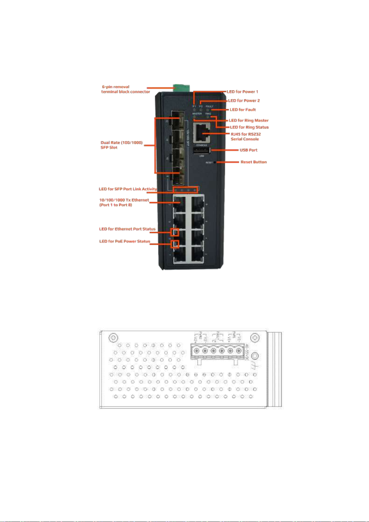
The front panel of the LT-PIGE-804GBTME series industrial PoE+ gigabit managed Ethernet switch is
shown below in Figure 2.2.
Figure 2.2: The Front Panel of LT-PIGE-804GBTME Series
Top View
Figure 2.3, below, shows the top panel of the LT-PIGE-804GBTME series switch that is equipped with
one 6-pin removal terminal block connector for dual DC power inputs (48-55VDC).
Figure 2.3: Top Panel View of LT-PIGE-804GBTME Series

6
LED Indicators
There are LED light indicators located on the front panel of the industrial Ethernet switch that display
the power status and network status. Each LED indicator has a different color and has its own specific
meaning, see below in Table 2.1.
LED
Color
Description
P1
Green
On
Power input 1 is active
Off
Power input 1 is inactive
P2
Green
On
Power input 2 is active
Off
Power input 2 is inactive
Fault
Green
On
System is ready
Off
System is booting
Red
On
Fault alarm event triggered
Off
Normal state
Master
Green
On
ERPS Owner Mode (Ring Master) is ready
Off
ERPS Owner Mode is not active
Ring
Green
On
Ring Network is active and works well
Flashing
Ring works abnormally or misconfigure
Off
Ring Network is not active
LINK/ACT
(SFP Port)
Green
On
Connected to network
Flashing
Networking is active with 1000Mbps
Off
Not connected to network
Amber
On
Connected to network
Flashing
Networking is active with 100Mbps
Off
Not connected to network
LAN Port 1-8
(Left LED)
Green
On
Connected to network, 10/100/1000Mbps
Flashing
Networking is active
Off
Not connected to network
LAN Port 1-8
(Right LED)
Green
On
The port is supplying power to the powered-device
Off
No powered-device attached or power supplying fails
Table 2.1: LED Indictors for LT-PIGE-804GBTME Series

7
Ethernet Ports
RJ-45 Ports(Auto MDI/MDIX)
The RJ-45 ports are auto-sensing for 10Base-T, 100Base-TX or 1000Base-T devices connections. Auto
MDI/MDIX means that the switch can connect to another switch or workstation without changing the
straight-through or crossover cabling. See the figures as below for straight-through and crossover
cabling schematics.
RJ-45 Pin Assignments (Table 2.2)
Table 2.2: RJ-45 Pin Assignments
Note: “+” and “-” signs represent the polarity of the wires that make up each wire pair.
All ports on this industrial Ethernet switch support automatic MDI/MDI-X operation. Users can use
straight-through cables (see Figure 2.4) for all network connections to PCs, servers, other switches or
hubs. With straight-through cable, pins 1, 2, 3, and 6, at one end of the cable, are connected straight
through to pins 1, 2, 3 and 6 at the other end of the cable. The table below (Table 2.3) shows the
10BASE-T, 100BASE-TX, 1000BASE-TX MDI and MDI-X port pin outs.
Table 2.3: Ethernet Signal Pin Outs
The following figures show the cabling schematics for straight-through and crossover.
Figure 2.4: Straight-Through Cable Schematic
Figure 2.5: Crossover Cable Schematic

8
The following figures show the 10,100, and 1000 Ethernet RJ-45 pin outs.
Figure 2.6: RJ45 Ethernet Port Pin Outs
Figure 2.7: Straight-Through Cable Schematic
Figure 2.8: Crossover Cable Schematic
Cabling
Use the four twisted-pair, category 5e, or the above cabling for RJ-45 port connections. The cable
between the switch and the link partner (switch, hub, workstation, etc.) must be less than 100 meters
(328 ft.) long.
The small form-factor pluggable (SFP) is a compact optical transceiver used in optical communications
for both telecommunication and data communication applications.

9
To connect the transceiver and LC cable, please follow below steps:
Step 1. Insert the SFP transceiver module into the SFP slot as shown below in Figure 2.9. Notice that
the triangle mark is at the bottom of the SFP slot. Figure 2.10 shows SFP transceiver module
was inserted.
Figure 2.9: Transceiver to the SFP Module
Figure 2.10: Transceiver Inserted
Step 2. Insert the fiber cable of the LC connector into the transceiver as shown below in Figure 2.11.
Figure 2.11: LC Connector to the Transceiver

10
To remove the LC connector from the transceiver, please follow the steps shown below:
Step 1. Press the upper side of the LC connector from the transceiver and pull it out to release as
shown below in Figure 2.12
Figure 2.12: Remove LC Connector
Step 2. Push down the metal clasp and pull the transceiver out by the plastic part as shown below in
Figure 2.13
Figure 2.13: Pull Out from the SFP Module
11
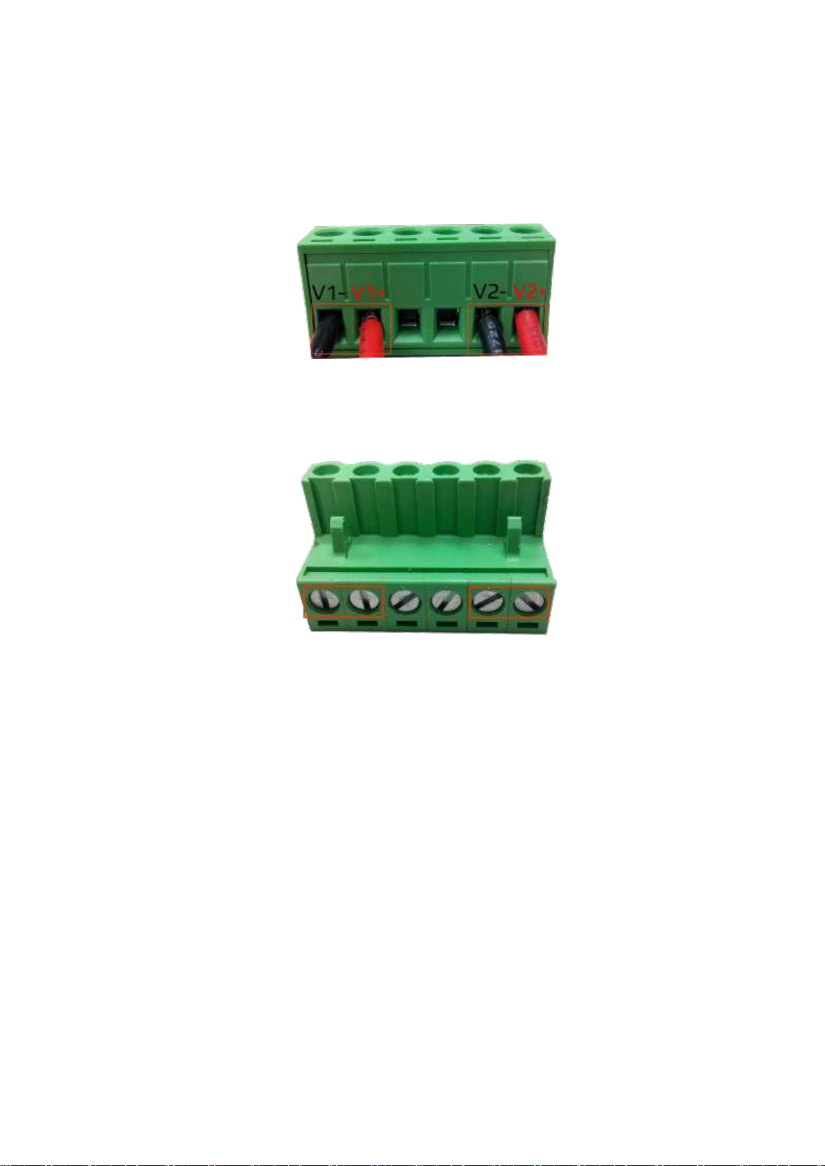
Wiring the Power Inputs
Please follow the below steps to insert the power wire.
Step 1. Insert the positive and negative wires into the PWR1 (V1+, V1-) and PWR2 (V2+, V2-) contacts
on the terminal block connector as shown below in Figure 2.14.
Figure 2.14: Power Terminal Block
Step 2. Tighten the wire-clamp screws to prevent the wires from loosening, as shown below in Figure
2.15.
Figure 2.15: Power Terminal Block
Note:
Only use copper conductors, 60/75°C, tighten to 5 lbs.
The wire gauge for the terminal block should range between 18~20 AWG.

12
Wiring the Fault Alarm Contact
The fault alarm contact is in the middle of the terminal block connector as the picture shows below in
Figure 2.16. By inserting the wires, it will detect the fault status including power failure or port link
failure (managed industrial switch only) and form a normally open circuit. An application example for
the fault alarm contact is shown below in Figure 2.16.
Figure 2.16: Wiring the Fault Alarm Contact
Note:
The wire gauge for the terminal block should range between 12 ~ 24 AWG.
If only using one power source, jumper Pin 1 to Pin 5 and Pin 2 to Pin 6 to eliminate power
fault alarm.

13
Mounting Installation
DIN-Rail Mounting
The DIN-Rail is pre-installed on the industrial Ethernet switch from the factory. If the DIN-Rail is not on
the industrial Ethernet switch, please see Figure 3.1 to learn how to install the DIN-Rail on the switch.
Figure 3.1: The Rear Side of the Switch and DIN-Rail Bracket
Follow the steps below to learn how to hang the industrial Ethernet switch.
Step 1. Use the screws to install the DIN-Rail bracket on the rear side of the industrial Ethernet
switch.
Step 2. To remove the DIN-Rail bracket, do the opposite from Step 1.
Step 3. After the DIN-Rail bracket is installed on the rear side of the switch, insert the top of the DIN-
Rail on to the track as shown below in Figure 3.2.

14
Figure 3.2: Insert the Switch on the DIN-Rail
Step 4. Lightly pull down the bracket on to the rail as shown below in Figure 3.3.
Figure 3.3: Stable the Switch on DIN-Rail
Step 5. Check if the bracket is mounted tightly on the rail.
Step 6. To remove the industrial Ethernet switch from the rail, do the opposite from the above steps.
15
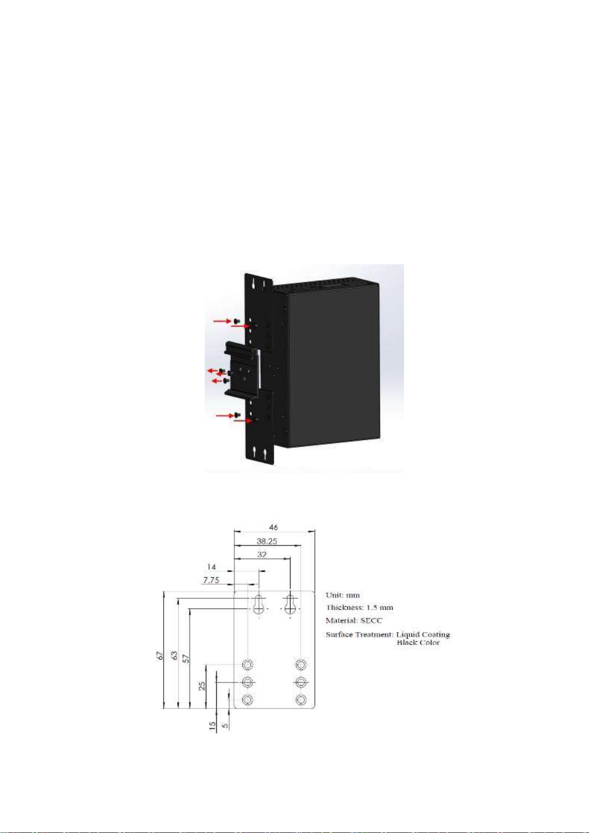
Wall Mounting
Follow the steps below to mount the industrial Ethernet switch using the wall mounting bracket as
shown below in Figure 3.4.
Step 1. Remove the DIN-Rail bracket from the industrial Ethernet switch by loosening the screws.
Step 2. Place the wall mounting brackets on the top and bottom of the industrial Ethernet switch.
Step 3. Use the screws to screw the wall mounting bracket on the industrial Ethernet switch.
Step 4. Use the hook holes at the corners of the wall mounting bracket to hang the industrial
Ethernet switch on the wall.
Step 5. To remove the wall mount bracket, do the opposite from the steps above.
Figure 3.4: Remove DIN-Rail Bracket from the Switch
Below, in Figure 3.5 are the dimensions of the wall mounting bracket.
Figure 3.5: Wall Mounting Bracket Dimensions

16
Hardware Installation
Installation Steps
This section will explain how to install LT-PIGE-804GBTME series: 12-port industrial PoE+ gigabit
managed Ethernet switch, with 8*10/100/1000Tx (PSE 30W/Port) and 4*100/1000 SFP Slots
Installation Steps
Step 1. Unpack the industrial Ethernet switch from the original packing box.
Step 2. Check if the DIN-Rail bracket is screwed on the industrial Ethernet switch.
If the DIN-Rail is not screwed on the industrial Ethernet switch, please refer to the DIN-Rail
Mounting section for DIN-Rail installation.
If you want to wall mount the industrial Ethernet switch, please refer to the Wall Mounting
section for wall mounting installation.
Step 3. To hang the industrial Ethernet switch on a DIN-Rail or wall, please refer to the Mounting
Installation section.
Step 4. Power on the industrial Ethernet switch and then the power LED light will turn on.
If you need help on how to wire power, please refer to the Wiring the Power Inputs section.
Please refer to the LED Indicators section for LED light indication.
Step 5. Prepare the twisted-pair, straight-through category 5 cable for Ethernet connection.
Step 6. Insert one side of the RJ-45 cable into switch’s Ethernet port and on the other side into the
networking device’s Ethernet port, e.g. switch PC or server. The Ethernet port’s (RJ-45) LED
on the industrial Ethernet switch will turn on when the cable is connected to the networking
device.
Please refer to the LED Indicators section for LED light indication.
Step 7. When all connections are set and the LED lights all show normal, the installation is complete.
Table of contents
Other Barox Switch manuals


