Barreto 912HM User manual

912 Owner’s Manual
8/31/21
Page 1 of 16
TH
E
MODEL 9
12HM
HY
D
RAULIC TR
E
NCHER
OWNER’S MANUAL
CONGRATULATIONS!
You are now the proud owner of the BARRETO trencher. The OPERATOR’S MANUAL is
attached to the machine. Please study it and this manual to become familiar with the trencher, its
characteristics, and method of operation. Pay particular attention to the safety and operating
instructions to prevent personal injury or equipment damage.
If you have any questions or need any replacement parts in the future, please contact us at your
convenience. Our toll-free phone number, fax and email are listed below.
THANK YOU for your patronage and confidence in BARRETO equipment.
Barreto Manufacturing, Inc.
Innovative Equipment Engineered to Last
66498 Hwy 203, La Grande, OR 97850
(800) 525-7348 (541) 963-7348
FAX (541) 963-6755
E-Mail: info@barretomfg.com
Web Site: http://www.barretomfg.com
Machine Identification Record
Machine model number ________________________
Machine serial number ________________________
Engine manufacturer ________________________
Engine model number ________________________
Engine serial number ________________________

912 Owner’s Manual
8/31/21
Page 2 of
16
TABLE OF CONTENTS
TRENCHER DELIVERY AND ASSEMBLY INSTRUCTIONS 3
SERVICE INFORMATION 3
HOUR METER 4
TRENCHER INTENDED USE 4
CHAIN INSTALLATION 5
MAINTENANCE PREPARATION 5
WARRANTY OF BARRETO MANUFACTURING EQUIPMENT 6
ROUTINE MAINTENANCE 6
WHEEL DRIVE VALVE CABLE ADJUSTMENT 7
WHEEL DRIVE NEUTRAL ADJUSTMENT 8
CHAIN VALVE ADJUSTMENT 9
LUBRICATION REQUIREMENTS 10
ELECTRICAL SCHEMATIC - HONDA GX270 11
HYDRAULIC SCHEMATIC 12
SPECIFICATIONS 13
TROUBLESHOOTING GUIDE 14
INDEX 16
TRENCHER DELIVERY AND ASSEMBLY
INS
T
RUC
TIO
NS
Upon delivery, check for freight damage and any missing items. Report any damage immediately to the
carrier and Barreto Manufacturing and take pictures if possible. Remove trencher from shipping crate.
When documentation refers to “right side” or “left side”, it is relative to the operator’s position with both
hands on the handlebars.
Install cushion pad, boom cushion, and boom. CAUTION!! The boom is heavy. You may want help to lift it
into place. Push boom on as far as it will go onto the boom mount (part of the chain motor housing
weldment). Be sure adjuster screw is backed out.

912 Owner’s Manual
8/31/21
Page 3 of
16
SERVICE
IN
F
O
R
MATIO
N
•Your trencher should arrive with 9.5 gallons of hydraulic fluid in the tank. Check reservoir level using
the sight glass on the right side of the tank. Shipping regulations may prohibit shipping with the
hydraulic fluid. If required, add tractor transmission / hydraulic fluid to the reservoir. For machine use in
ambient temperatures between +32°F (0°C) and +90°F (32°C) hydraulic fluid ISO 68 is recommended
with anti-foaming additives. If the machine is operated at temperatures below +32°F (0°C) then hydraulic
fluid ISO 46 is recommended.
•Recheck oil level after trencher has been run and oil has circulated through the components. Routinely
check the level thereafter.
•Change hydraulic fluid filter after the first 50 hours of use. Change it every 200 hours thereafter.
•Add approximately one quart (1 liter) of hydraulic fluid to the reservoir with each filter change.
•Discard the old filter according to environmental standards in your geographic area.
•Check all hydraulic fittings for leaks and tighten if necessary.
•The grease zerk on chain shaft housing should be greased after every 4 to 8 hours of use.
•The grease zerk in the front wheel should be greased after every 8 hours of use.
•Grease zerks on cylinder rod end and boom pivot should be greased daily.
•Grease zerks on each side of the boom cylinder and on front wheel hub should be greased once a week..
•Grease zerks on the wheel hubs and hub lock screws should be greased and freewheeled once a week or
so, depending upon free wheel use.
•The grease zerk in the chain roller bearing should be greased after every 4 to 8 hours of use.
(See page 10 for illustrations of lubrication points.)
IMPORTANT: The engine on the Barreto trencher is normally serviced prior to shipping. However,
shipping regulations may prohibit shipping with fuel or oil in the machine. Check levels and add oil and
fuel as required before starting engine. Service the en
g
ine according to the engine manual before startin
g
.
IMPORTANT: If the couplers between the engine and the pump are moved or
removed for any reason, it is CRITICAL that they have a 1/16” gap between them
when reinstalled. Failure to have this gap will result in rapid wear and failure of
your pump!
NOTE: It is very important to move the fuel shutoff lever to the closed position after
stopping the engine. Failure to do so could cause fuel to leak down into the cylinder and
crankcase. Damage resulting from this will void your engine warranty and not be covered.
WARNING: Running the trencher without hydraulic oil will cause serious damage to the hydraulic pump.
INSURE THAT THE RESERVOIR OIL LEVEL IS TO THE SIGHT GLASS BEFORE STARTING
THE MACHINE.

912 Owner’s Manual
8/31/21
Page 4 of
16
HOUR METER
The DGI®TACH/HOUR hour meter tracks the hours of machine operation in order for routine
maintenance to be performed on a timely basis.
Your DGI® hour meter is pre-set at the DGI® factory to go into Flash Alert mode at 25-hour
intervals. Although the engine manufacturer does not require changing engine oil this often, due
to heavy-duty use and extreme conditions inherent to tiller use, Barreto Manufacturing
strongly recommends frequent oil changes.
Refer to this manual for equipment service requirements and to the Engine Manual for other
engine service requirements.
While Flash Alert is active, hold the tip of the RESET TOOL (Key Kancel Wand) against the
meter as shown. Within several seconds, the display will stop flashing indicating the Service
Interval has been reset. If the wand gets lost, a small mechanic’s pick-up magnet will work.
RESET TOOL
TRENCHER INTENDED USE
This machine is designed for digging trenches in “normal” ground of reasonably soft dirt and
stones up to 6” (15cm) in diameter. Ground with larger stones, high clay content, very hard
packed, very dry, or in a frozen condition may be unsuitable for normal trenching. Consider using
a backhoe or other heavier equipment for such conditions.

912 Owner’s Manual
8/31/21
Page 5 of
16
CHAIN INSTALLATION
1. Slide chain under sprocket, with teeth in the correct cutting direction. Properly
installed, the cutting edges of the chain will face forward on the top of the boom and
rearward on the bottom of the boom (see diagram below).
2. Push digging boom control lever forward to lower boom onto the chain.
3. Wrap chain around boom and sprocket. Install chain master link or link pin.
4. Use boom adjuster screw to tighten chain. Chain should have enough slack to allow
approximately 1" to 2" of space between middle of boom and chain when boom and
chain are straight out in a horizontal position.
5. Tighten adjuster screw locknut.
Forward Cutting ed
g
e
Cutting edge Rearward
MAINTENANCE PREPARATION
Only trained & qualified personnel should perform maintenance or repairs of the trencher. Before
performing any service, maintenance, adjustments, repairs, or off-season long-term storage,
follow the SHUT DOWN PROCEDURE in the OPERATOR’S MANUAL.
Do not touch the engine, muffler, or any of the hydraulic components until cool.
WARNING: Muffler and engine get hot enough to cause serious burns. For the
safety of yourself and others, allow enough time for the engine, muffler, and the
hydraulic fluid to cool completely before performing any cleaning or maintenance.
Avoid contact with hydraulic fluid.
WARNING: When machine is operating, hydraulic fluid is under extreme pressure and
can get under skin and burn or poison.
If you need to lower the dig chain boom without power, do the following:
1. Position a pan under the trencher to catch hydraulic fluid.
2. Support the boom front end with a hoist or forklift.
WARNING: The boom with dig chain is heavy. Manpower alone is not recommended,
but if necessary, use a team of two strong workers to support the boom, and a third
worker to loosen the hose.
3. Loosen the hose at the rod end (front) port of the boom cylinder and lower the boom.
4. If it still will not lower, then loosen the hose at the back end port of the boom cylinder.

912 Owner’s Manual
8/31/21
Page 6 of
16
BARRETO MANUFACTURING,
INC
.
EQUIPMENT
WARRANTY
Barreto Manufacturing, Inc. warrants all BARRETOequipment to be free of defects in material
and workmanship for a period of one (1) year. All BARRETO fuel components, fuel tank, cap,
lines & fittings are warranted for two (2) years. Warranty period begins on date of delivery to the
original user.
This warranty is in lieu of all other warranties, whether written or implied, and is limited to:
1. Replacement of parts returned to the dealer and/or factory and determined defective
upon inspection. (Replacement for parts to dealers shall be at dealer cost plus
shipping charges.)
2. Time for pick-up and/or delivery, transportation of service calls by dealers is
excluded. Manufacturer reserves the right to determine reasonable time
required for repair.
Warranty does not apply to damage caused by abuse or neglect. Time and materials
required for normal maintenance and service are also excluded from warranty coverage.
Engines, engine attached fuel tanks, engine accessories, batteries and tires are warranted by
the original manufacturer and are not covered by the Barreto Equipment Warranty.
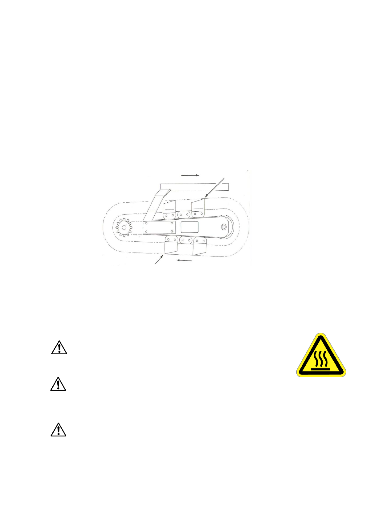
Wear parts such as dig chains, dig teeth, sprockets, chain rollers, bearings, bushings etc.
are excluded unless it can be determined that a defect has contributed to premature wear.
ROUTINE MAINTENANCE
Routinely check the condition and clean, tighten, repair, or replace as necessary the following:
•Dig chain boom guard, muffler guard, hydraulic hoses and fittings
•Fuel lines, fasteners, Safety decals
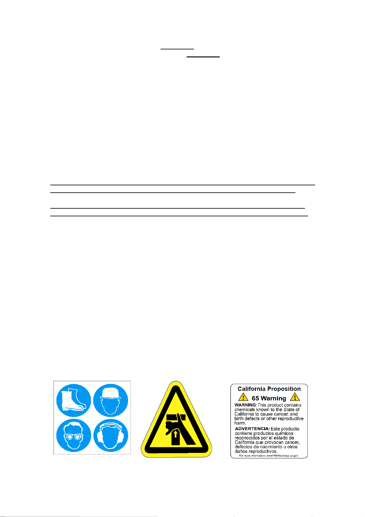
Clean safety decals often using soap and water. Do not use abrasive cleaners or solvents such as
mineral spirits that may damage the decals. Replace any damaged (unreadable) or missing decals.
If you replace a machine part that has one or more decals affixed to it, replace the decals also.
Replacement parts and decals can be purchased from Barreto Manufacturing, Inc. When attaching
decals, the temperature of the mounting surface must be at least 40°F (5°C) and must be clean
and dry.
Service the engine according to the engine owner’s manual. Follow the directions for all aspects
of service including air filter change, oil level checking, filling, draining, disposal of engine oil,
disposal of petrol/gasoline, and off-season long-term storage.
Off-season long-term storage of the trencher can be at any ambient temperature.

912 Owner’s Manual
8/31/21
Page 7 of
16
WHEEL DRIVE VALVE CABLE ADJUSTMENT
The clutch cable and lever must have some free play. The cable will stretch and
occasionally needs adjustment.
1. Rotate the actuator arm clockwise, by hand, to take up any free play. Measure the
distance from the pin of the actuator arm to the end of the cable housin
g.
2. Pull the clutch lever all the way up until it touches the handle bar grip. With the lever
pulled up, again measure the distance from the pin of the lever to the cable housing.
Calculate the difference.
3. Adjust the cable for 7/16" to 1/2" movement of the actuator arm at the pin. Do not
include any lever free play in the measurements.
To see a video on how to do this adjustment, enter the following address in your browser
URL window: https://www.youtube.com/watch?v=utUdozpYBcg&feature=youtu.be

912 Owner’s Manual
8/31/21
Page 8 of
16
WHEEL DRIVE NEUTRAL ADJUSTMENT
The speed control cables may need to be adjusted after some use. If the machine creeps
while the speed control is in neutral, the speed cables will need adjustment. Adjust the
cables to bring the pump cable arm to the neutral position (vertical) when the speed control
also is in neutral. Adjust the cables to eliminate slack, but do not over ti
g
hten them so they
are extremely tight against each other.

912 Owner’s Manual
8/31/21
Page 9 of
16
CHAIN VALVE ADJUSTMENT
The chain valve control should be adjusted to completely activate the chain valve when the
dig chain control is in the ON
'
position. To check this adjustment, put the chain on/off
control in ON position (with engine stopped). Pull the clutch lever on left handlebar up until
it touches the handgrip. While holding clutch lever up, push on the chain
forward/neutral/reverse lever. It should be at the end of its stroke, thus not move down any
more. If the chain F/N/R lever can be pushed down more, the valve spool lever should be
adjusted. To adjust, remove back cover from the control panel. Loosen the 2 bolts on valve
lever and rotate the lever plate down about 1/16". Re-tighten the bolts and check the lever
stroke. Adjust so the valve lever comes to the end of its stroke just as the clutch lever touches
the handgrip when chain valve control is in ON position.

912 Owner’s Manual
8/31/21
Page 10 of
16
DAILY LUBRICATION REQUIREMENTS
Be sure to grease all lubrication points as outlined on page 3 of this
manual.

912 Owner’s Manual
8/31/21
Page 11 of
16
ELECTRICAL SCHEMATIC - HONDA GX270

912 Owner’s Manual
8/31/21
Page 12 of
16
HYDRAULIC SCHEMATIC

912 Owner’s Manual
8/31/21
Page 13 of
16
SPECIFICATIONS
MODEL NUMBER 912HM
DIMENSIONS
Weight 620 lb. (281.23kg)
Height 43” (1.09m)
Length 81” (2.06m)
Width 28” (711.2mm)
Wheel Base 30” (762.25mm)
ENGINE
Engine Options Honda GX270
Fuel Gasoline
Power: hp (kW) at 3600 RPM 8.5 hp (6.34kW)
Fuel Capacity 0.95 U.S. gallons (3.6 liters)
Engine Oil Capacity 0.63 quarts (.60 liters)
Hour Meter Standard
HYDRAULIC SYSTEM
Reservoir Capacity 9.5 U.S. gallons (35.96 liters)
OPERATIONS
Ground Drive, Forward 132 feet per minute (40.23m/min)
Digging Chain Speed 227 feet per minute (69.19m/min)
Ground Drive, Reverse 58 feet per minute (17.68m/min)
BOOM / CHAIN OPTIONS
Depths 12”, 18” or 24”**(30.48cm, 45.72cm or 60.96cm)
Widths Standard 4” (101.60mm),
Maximum 6” (152.4mm)
Chain Types Skip Cup, Double Cup, Bolted Shark,
Combo Shark, Welded Shark
**NOTE: 24” Depth only available in 4” width.

912 Owner’s Manual
8/31/21
Page 14 of
16
912 TRENCHER TROUBLE SHOOTING GUIDE
CAUTION!! Always use extreme care when trouble shooting or making adjustments on the trencher.
Stay clear of the chain and auger when the engine is running. Stop the engine before disassembling any
component.
A. Entire hydraulic system does not operate and the engine is not under load.
1. Broken or improperly adjusted clutch
(actuator) cable
See clutch cable and actuator arm adjustment. Adjust
or replace cable.
2. Low hydraulic oil in tank
Add oil until it shows in sight gauge.
3. Hydraulic pump-to-engine coupler has
slipped.
Check for wear and replace both coupler halves and
rubber spider, as needed.
B. Engine lugs down or dies and wheels and chain do not turn.
1. Rocks or other obstructions stopping
chain.
Reverse chain momentarily to free it from obstruction.
Raise boom and stop chain. See if obstruction can be
removed from trench.
2. Trenching depth or speed too great for
soil conditions.
Decrease ground speed or trenching depth.
3. Engine improperly tuned or maintained.
See engine manual and correct as needed.
4. Low oil alert causes engine to shut
down.
This may occur when trenching on hills. Level
trencher, check oil and allow oil alert to reset.
5. Engine losing power due to wear.
See engine manual.
C. Chain fails to rotate, but wheel drive works.
1. Chain motor worn.
Rebuild motor or replace. New motors are available
from Barreto Manufacturing.
2. Chain Control Relief Valve
malfunctioning.
Adjust Relief Valve to 2200 psi or replace relief spring
if needed.
3. Sprocket spindle spline teeth worn or
broken.
Replace spindle.

912 Owner’s Manual
8/31/21
Page 15 of
16
912 TRENCHER TROUBLE SHOOTING GUIDE (Continued)
CAUTION!! Always use extreme care when trouble shooting or making adjustments on the trencher.
Stay clear of the chain and auger when the engine is running. Stop the engine before disassembling any
component.
D. Wheels fail to turn, but chain rotates.
1. Hubs unlocked.
Lock the hubs.
2. Wheel axle key sheared.
Replace key and other parts as needed.
3. Wheel Drive Valve not fully activated.
Adjust valve cable as shown on page 8.
4. Speed Cable broken or disconnected.
Replace or re-connect cable.
5. Pump Cable Lever loose on shaft.
Tighten setscrew on Pump Lever.
E. Oil leaks in hydraulic system.
1. Fittings are loose.
Tighten fittings on hoses and adapters.
2. Worn or broken hoses.
Replace damaged hoses.
3. Oil around chain motor or shaft.
Inspect motor for leaking shaft seal. Rebuild or replace
motor. New motors are available from Barreto
Manufacturing.
F. Foaming hydraulic oil coming from breather hose.
1. Improper oil used.
Verify that hydraulic fluid used had antifoaming
additives. Tractor transmission / hydraulic fluid ISO 68
is recommended for use in temperatures above +32°F.
2. Air leaking into oil.
Inspect and tighten fittings and clamps on pump and
hoses.
G. Boom does not lift, or does not lower into ground.
1. Boom lift relief valve
malfunctioning
Adjust relief to 500 psi. This may require a
replacement spring in valve.

912 Owner’s Manual
8/31/21
Page 16 of
16
INDEX
ADJUSTMENTS, 5, 7, 8, 9, 14, 15
BOOM, 2, 3, 5, 6, 14, 15
CHAIN, 2, 3, 5, 6, 9, 13, 14, 15
CHAIN INSTALLATION,5
CHAIN VALVE ADJUSTMENT, 2, 9
CLUTCH CABLE, 7, 14
DAILY LUBRICATION REQUIREMENTS, 10
ELECTRICAL SCHEMATIC - HONDA GX270, 2, 11
ENGINE, 3, 4, 5, 6, 9, 14, 15
GREASE, 3, 10
HOUR METER, 4
HYDRAULIC FILTER, 3, 6
HYDRAULIC FLUID, 3, 5, 15
HYDRAULIC SCHEMATIC, 2, 12
MAINTENANCE, 5, 6
SAFETY DECALS, 6
SIGHT GLASS, 3
SPECIFICATIONS, 13
SPEED CABLE,8
TRENCHER DELIVERYANDASSEMBLY
INS
T
RUC
TIO
NS
, 2
TRENCHER INTENDED USE, 4
TRENCHER TROUBLE SHOOTING GUIDE, 14, 15
WARRANTY, 6
WHEEL DRIVE NEUTRAL ADJUSTMENT, 2, 8
WHEEL DRIVE VALVE CABLE ADJUSTMENT, 2, 7
Table of contents
Other Barreto Construction Equipment manuals

Barreto
Barreto E30SG User manual

Barreto
Barreto 712MTH User manual

Barreto
Barreto HT712 User manual

Barreto
Barreto E30SGB User manual

Barreto
Barreto 912RM User manual

Barreto
Barreto 20RTK User manual

Barreto
Barreto 13STKH User manual

Barreto
Barreto 1324TK User manual

Barreto
Barreto 1324 User manual

Barreto
Barreto 712MT User manual
Popular Construction Equipment manuals by other brands

Husqvarna
Husqvarna LF 50 Operator's manual

Broderson
Broderson IC-280-A ACCOMPANIMENT TO THE INSTALLATION, OPERATION AND MAINTENANCE MANUAL

Larzep
Larzep VA1225 instruction manual

TOPMAQ
TOPMAQ HHW-2D instruction manual

GOCMAKSAN
GOCMAKSAN B45X1 operating & maintenance manual

Textron
Textron Greenlee 882 instruction manual