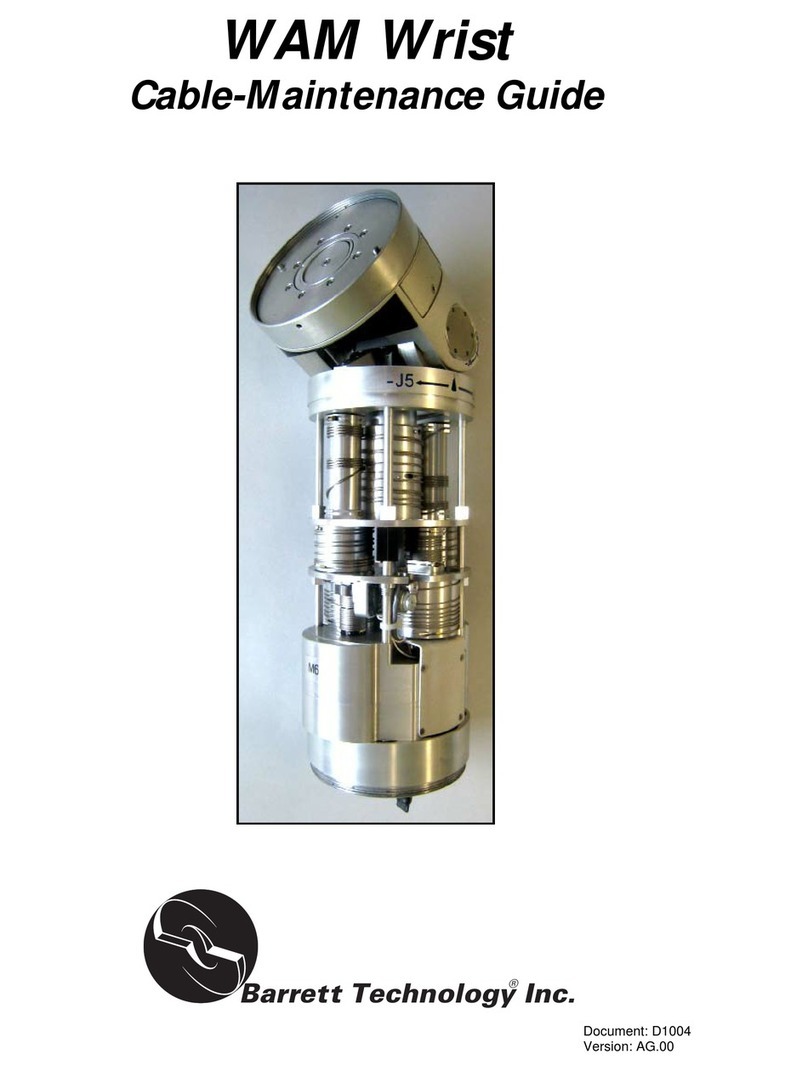
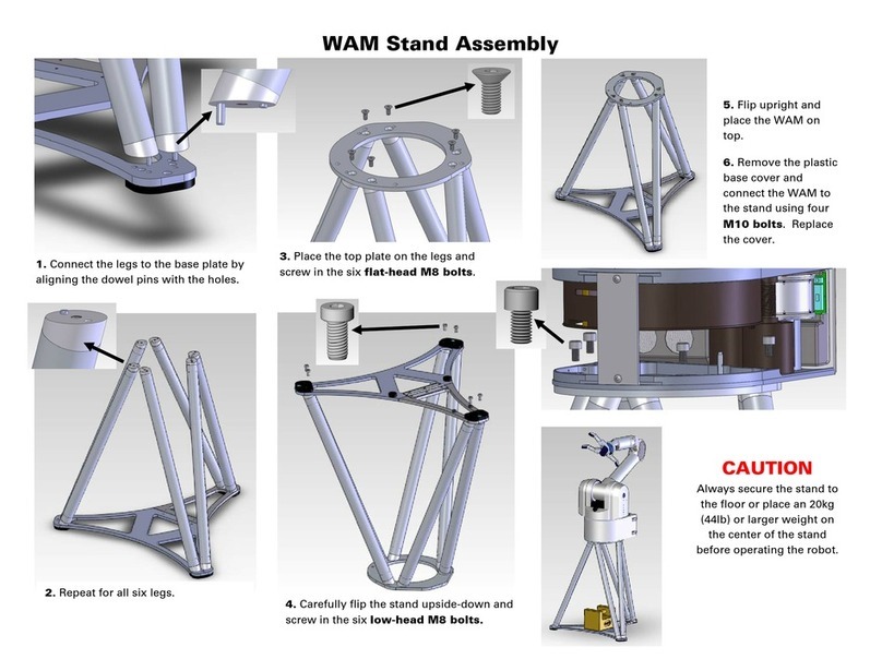
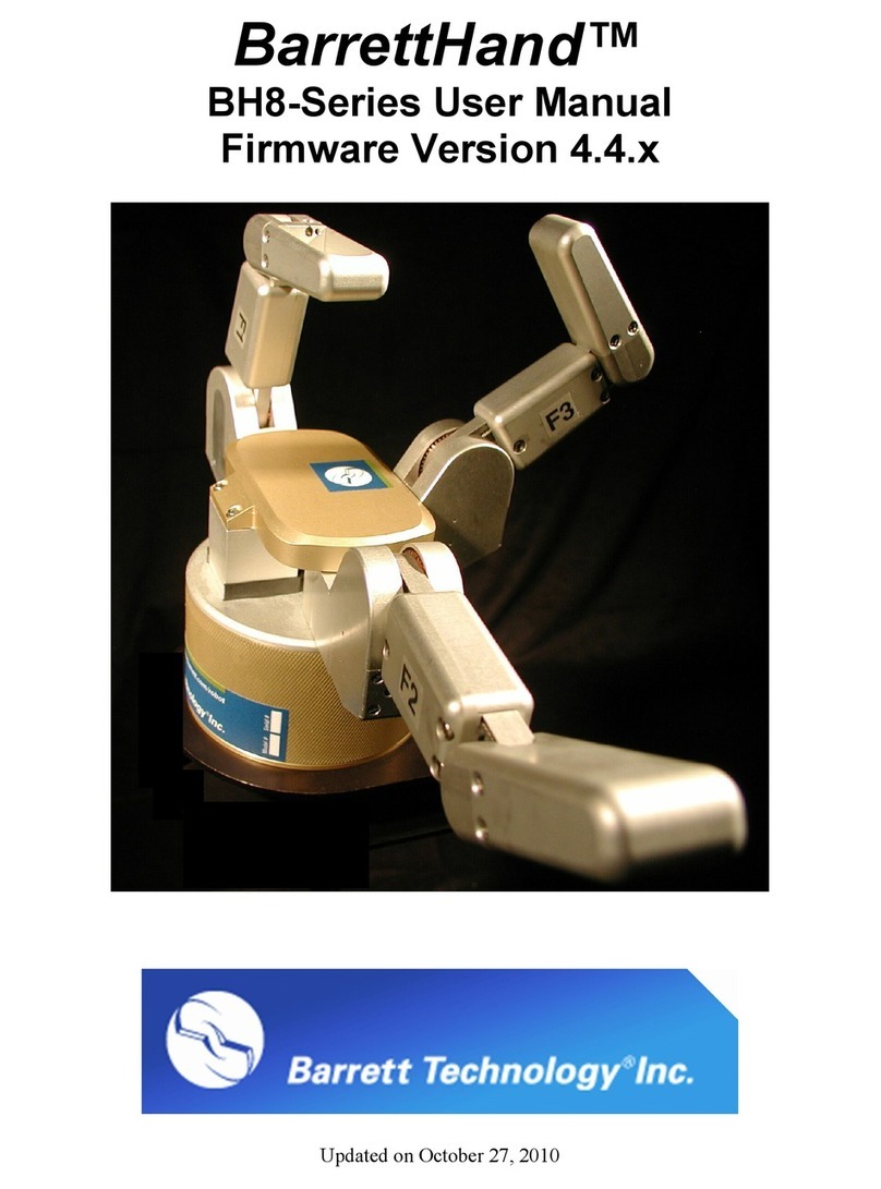
Barrett WAM Arm User manual

WAMTM Arm
User’s Manual
Document: D1001
Version: AH.00

© 2008 Barrett Technology®, Inc. Document: D1001, Version: AH.00 2 of 80
Table of Contents
TABLE OF CONTENTS...............................................................................................................1
TABLE OF CONTENTS...............................................................................................................2
LIST OF FIGURES........................................................................................................................4
LIST OF TABLES..........................................................................................................................5
LIST OF EQUATIONS .................................................................................................................5
1SYSTEM DESCRIPTION.....................................................................................................6
1.1 STANDARD WAM SYSTEM COMPONENTS......................................................................... 6
1.1.1 System Features........................................................................................................6
1.1.2 Documentation..........................................................................................................6
1.1.3 WAM Arm.................................................................................................................7
1.1.4 Tool-End Attachments ..............................................................................................8
1.1.5 Power Supply.......................................................................................................... 10
1.1.6 Safety Pendants.......................................................................................................10
1.1.7 Electrical Cables ....................................................................................................11
1.1.8 Control Software and Firmware.............................................................................11
1.1.9 Maintenance Kit .....................................................................................................11
1.2 SYSTEM OPTIONS ............................................................................................................ 13
1.2.1 WAM Wrist .............................................................................................................13
1.2.2 Passive Gimbals .....................................................................................................14
1.2.3 External WAM PC..................................................................................................15
1.2.4 Control Software/Firmware Upgrades...................................................................16
2SAFETY AND CAUTIONS.................................................................................................16
2.1 SAFETY INSTRUCTIONS ................................................................................................... 16
2.2 SAFETY SYSTEM:PENDANTS........................................................................................... 17
2.2.1 Safety States............................................................................................................17
2.2.2 Status Lights ...........................................................................................................17
2.3 HANDLING SAFETY FAULTS ............................................................................................ 18
3SYSTEM SETUP..................................................................................................................19
3.1 MOUNTING ...................................................................................................................... 19
3.2 GROUNDING .................................................................................................................... 20
3.3 INSTALLING THE EXTERNAL PC (OPTIONAL) .................................................................. 20
3.3.1 Physical Installation...............................................................................................20
3.3.2 Software installation...............................................................................................20
3.4 WAM WRIST (OPTIONAL) .............................................................................................. 20
3.5 SAFETY BOARD SETTINGS ............................................................................................... 22
3.6 ELECTRICAL CONNECTIONS ............................................................................................ 23
3.6.1 Power Source..........................................................................................................23
3.6.2 Pendants.................................................................................................................23
3.6.3 Communications.....................................................................................................24
3.7 POWER-UP SEQUENCE..................................................................................................... 24
3.8 CODE EXAMPLES............................................................................................................. 25
4PC & CONTROL SOFTWARE..........................................................................................26
4.1 LIBRARY OVERVIEW ....................................................................................................... 26
4.2 FILE SYSTEM LAYOUT..................................................................................................... 27
4.3 THE CONFIGURATION FILE (WAM.CONF)......................................................................... 27
4.4 OPERATING MODES......................................................................................................... 27
4.5 UPDATING FIRMWARE..................................................................................................... 28
4.5.1 Pucks™...................................................................................................................28

© 2008 Barrett Technology®, Inc. Document: D1001, Version: AH.00 3 of 80
4.5.2 Safety Board........................................................................................................... 29
5WAM COMMANDS LIST.................................................................................................. 30
6WAM PROPERTIES LIST................................................................................................. 31
6.1 COMMON PROPERTIES..................................................................................................... 31
6.2 MOTOR PROPERTIES........................................................................................................ 36
6.3 SAFETY-MODULE PROPERTIES........................................................................................ 42
6.4 KEY TO PROPERTY TABLE............................................................................................... 45
7CANBUS COMMUNICATION SPECIFICATIONS....................................................... 46
7.1 DATA LINK SPECIFICATIONS ........................................................................................... 46
7.2 CANBUS TIMING ............................................................................................................ 46
7.3 ID SPECIFICATIONS ......................................................................................................... 46
7.3.1 Message IDs........................................................................................................... 46
7.3.2 Motor IDs and Groups........................................................................................... 46
7.4 CANBUS FRAME DATA PAYLOAD .................................................................................. 47
7.4.1 Standard CANbus Message Format....................................................................... 47
7.4.2 Exceptions .............................................................................................................. 47
7.5 FULL COMMUNICATION EXAMPLE .................................................................................. 48
8TROUBLESHOOTING....................................................................................................... 49
8.1 CHECKING THE ERROR LOG ............................................................................................ 49
8.2 COMMON PROBLEMS ...................................................................................................... 50
9THEORY OF OPERATION............................................................................................... 56
9.1 ELECTRONIC ARCHITECTURE .......................................................................................... 56
9.2 KINEMATICS,TRANSMISSION RATIOS,AND JOINT RANGES ............................................ 58
9.2.1 4 DOF and 7 DOF ................................................................................................. 58
9.2.2 4 DOF with Gimbals.............................................................................................. 66
9.2.3 Motor-to-Joint Transformations............................................................................. 68
APPENDIX A INTEGRATING A BARRETTHAND™ ................................................... 70
APPENDIX B TECHNICAL SPECIFICATIONS............................................................. 71
APPENDIX C FAQ ............................................................................................................... 74
APPENDIX D GLOSSARY.................................................................................................. 76
INDEX........................................................................................................................................... 79

© 2008 Barrett Technology®, Inc. Document: D1001, Version: AH.00 4 of 80
List of Figures
FIGURE 1-WAM ARM ..................................................................................................................... 7
FIGURE 2-BLANK OUTER LINK ........................................................................................................ 8
FIGURE 3-END PLATES OF WRIST AND OUTER LINK........................................................................ 8
FIGURE 4–HAPTIC BALL .................................................................................................................. 9
FIGURE 5–TOOL PLATE ................................................................................................................... 9
FIGURE 6–CAN TERMINATION ........................................................................................................ 9
FIGURE 7–POWER SUPPLY ............................................................................................................. 10
FIGURE 8–SAFETY PENDANTS ....................................................................................................... 10
FIGURE 9–ELECTRICAL CABLES .................................................................................................... 11
FIGURE 10 –MAINTENANCE KIT ..................................................................................................... 12
FIGURE 11 –WAM WRIST .............................................................................................................. 13
FIGURE 12 –WRIST MAINTENANCE KIT.......................................................................................... 14
FIGURE 13 –GIMBALS OPTION........................................................................................................ 15
FIGURE 14 –EXTERNAL WAM PC.................................................................................................. 15
FIGURE 15 –BACK OF EXTERNAL WAM PC................................................................................... 15
FIGURE 16 –WAM WORKSPACE .................................................................................................... 16
FIGURE 17 –WAM RESPONSES TO ERRORS AND REQUESTS........................................................... 19
FIGURE 18 –SCREW-HOLE LOCATIONS ........................................................................................... 19
FIGURE 19 –MOUNTING-HOLE MEASUREMENTS............................................................................ 19
FIGURE 20 –WRIST CONNECTOR .................................................................................................... 21
FIGURE 21 –SEPARATING THE OUTER LINK.................................................................................... 21
FIGURE 22: CLOSE-UP OF OUTER LINK CONNECTION ...................................................................... 21
FIGURE 23 –SAFETY BOARD SWITCHES.......................................................................................... 22
FIGURE 26 –DC POWER CABLE (BLUE) .......................................................................................... 23
FIGURE 27 –PENDANT CABLES....................................................................................................... 23
FIGURE 28 –WIRELESS ACCESS POINT ON WAM BACKPLATE ....................................................... 24
FIGURE 29 –CAN CABLE (PURPLE)................................................................................................. 24
FIGURE 30 –SAFETY BOARD COVER............................................................................................... 29
FIGURE 31 –SERIAL CABLE ............................................................................................................ 29
FIGURE 32 –SERIAL CONNECTION WITH SWITCH IN “ON”POSITION .............................................. 29
FIGURE 33 –WAM SYSTEM COMPONENTS ..................................................................................... 56
FIGURE 34 –WAM SYSTEM SCHEMATIC ........................................................................................ 57
FIGURE 35 –WAM 4-DOF DIMENSIONS AND D-H FRAMES ............................................................ 58
FIGURE 36 –WAM 7-DOF DIMENSIONS AND D-H FRAMES ............................................................ 59
FIGURE 37 –WAM ARM JOINT 1FRAMES AND LIMITS................................................................... 60
FIGURE 38 –WAM ARM JOINT 2FRAMES AND LIMITS................................................................... 60
FIGURE 39 –WAM ARM JOINT 3FRAMES AND LIMITS................................................................... 61
FIGURE 40 –WAM ARM JOINT 4FRAMES AND LIMITS................................................................... 61
FIGURE 41 –WAM ARM JOINT 5FRAMES AND LIMITS................................................................... 62
FIGURE 42 –WAM ARM JOINT 6FRAMES AND LIMITS................................................................... 62
FIGURE 43 –WAM ARM JOINT 7FRAMES AND LIMITS................................................................... 63
FIGURE 44 –DENAVIT-HARTENBERG FRAMES –4-DOF +GIMBALS .............................................. 66
FIGURE 45 –WAM DIMENSIONS .................................................................................................... 72
FIGURE 46 –TOOL PLATE DIMENSIONS........................................................................................... 73
FIGURE 47 –CABLE DIFFERENTIAL ................................................................................................. 74
FIGURE 48 –PUCKS™–MINIATURE BRUSHLESS MOTOR CONTROLLERS....................................... 74

© 2008 Barrett Technology®, Inc. Document: D1001, Version: AH.00 5 of 80
List of Tables
TABLE 1–WAM COMMUNICATION SETTINGS ............................................................................... 22
TABLE 2–HAND COMMUNICATION AND POWER SETTINGS ........................................................... 22
TABLE 3–DC POWER REQUIREMENTS........................................................................................... 23
TABLE 4–4-DOF WAM FRAME PARAMETERS (WITH BLANK OUTER LINK INSTALLED) ................. 64
TABLE 5–7-DOF WAM FRAME PARAMETERS............................................................................... 64
TABLE 6–JOINT LIMITS ................................................................................................................. 65
TABLE 7–4-DOF WAM +GIMBALS DH PARAMETERS................................................................. 67
TABLE 8–ARM TRANSMISSION RATIOS ......................................................................................... 68
TABLE 9–MAXIMUM TORQUE (MT) MATO NM CONVERSION TABLE............................................ 75
List of Equations
EQUATION 1–D-H GENERALIZED TRANSFORM MATRIX ................................................................. 64
EQUATION 2–D-H MATRIX EXAMPLE ........................................................................................... 64
EQUATION 3–TOOL FRAME MATRIX .............................................................................................. 65
EQUATION 4–TOOL END TIP POSITION AND ORIENTATION EQUATION FOR THE 4-DOF WAM ....... 65
EQUATION 5–TOOL END TIP POSITION AND ORIENTATION EQUATION FOR THE 7-DOF WAM ....... 65
EQUATION 6–WAM MOTOR-TO-JOINT POSITION TRANSFORMATIONS .......................................... 68
EQUATION 7–WRIST MOTOR-TO-JOINT POSITION TRANSFORMATIONS.......................................... 68
EQUATION 8–ARM JOINT-TO-MOTOR POSITION TRANSFORMATIONS ............................................ 68
EQUATION 9–WRIST JOINT-TO-MOTOR POSITION TRANSFORMATION ........................................... 68
EQUATION 10 –ARM MOTOR-TO-JOINT TORQUE TRANSFORMATION.............................................. 69
EQUATION 11 –WRIST MOTOR-TO-JOINT TRANSFORMATIONS ....................................................... 69
EQUATION 12 –ARM JOINT-TO-MOTOR TORQUE TRANSFORMATIONS ............................................ 69
EQUATION 13 –WRIST JOINT-TO-MOTOR TORQUE TRANSFORMATIONS ......................................... 69

© 2008 Barrett Technology®, Inc. Document: D1001, Version: AH.00 6 of 80
1 System Description
1.1 Standard WAM*System Components
1.1.1 System Features
Thank you for choosing the Whole Arm Manipulator (WAM). The WAM is designed to overcome
the lack of backdrivability in conventional robotic arms while maintaining durability, low power
usage, light moving weight, and ease of use. The standard WAM is a four degree-of-freedom (4-
DOF) arm. The optional WAM Wrist adds three more degrees of freedom – see Section 1.2.1. The
WAM has the dexterity and slenderness to easily navigate around obstacles placed in its path and
is endowed with smooth and precise joint motion, contributing to the WAM’s popularity in
robotics control research and emerging applications.
The compactness, low system weight, and extraordinarily low power consumption make the
WAM arm uniquely portable and so an ideal choice for use with mobile platforms. Its low mass
and the absence of a controller cabinet ensure that it is significantly easier to mount than robotic
arms of the same size. The WAM can also be powered directly from small batteries on a mobile
platform without power conditioning, accepting a wide range of voltages from batteries.
While no robotic arm should be considered “safe” and all precautions should be taken as each
application demands, the backdrivability and the multiple-layer safety system of the WAM make it
one of the safest robotic arms available. Because of its 95% backdrivable cable drives (in contrast
to poorly-backdrivable gear and harmonic-based drives), the WAM can react naturally and lightly
as it contacts walls and people. These attributes have contributed to the WAM’s success as one of
the first robotic arms in surgery and rehabilitation.
We hope that you enjoy the versatility and functionality of the WAM. Please never hesitate to give
http://www.barrett.com/.
1.1.2 Documentation
The WAM comes with six separate pieces of documentation:
1. User’s Manual (this manual)
2. Quick Start Guide
3. WAM Cable Maintenance Guide
4. Wrist Cable Maintenance Guide
5. Inertial Specifications Manual
6. Support Reference Sheet
1. The User’s Manual (this manual) covers:
•System components and options
•Safety instructions
•System setup and operation
•Troubleshooting
•Technical specifications
•Frequently asked questions
2. The Quick Start Guide is a single page guide that covers the essentials of operating the WAM
and some basic demonstrations for the WAM. This includes turning on and initializing the
WAM, home position, fault recovery, and the gravity compensation and teach-and-play
demos.
*“Whole Arm Manipulator” and “WAM” are trademarks of Barrett Technology® Inc.

© 2008 Barrett Technology®, Inc. Document: D1001, Version: AH.00 7 of 80
3. The WAM Cable Maintenance Guide covers the cabling of joints 1 through 4 and the general
rules for handling cables, and should be used in the event that a cable in the 4-DOF WAM is
damaged or is coming loose.
4. The Wrist Cable Maintenance Guide covers the cabling of joints 5 and 6 and should be used
with the introductory sections in the WAM Cable Maintenance Guide in the event that a cable
in the Wrist is damaged
5. The Inertial Specifications Manual presents the inertial data for the WAM robotic arm (the 4-
DOF version and both 7-DOF versions) in support of computed-torque control techniques.
6. The Support Reference Sheet lists the variety of support options Barrett provides and assists
the customer in using the resource most likely to answer their question most effectively.
1.1.3 WAM Arm
The standard four-degree-of-freedom WAM Arm, shown in Figure 1, has four cable-driven joints
labeled J1 through J4, and four brushless DC motors labeled M1 through M4. M1 controls the yaw
(J1) of the WAM and is located in the base of the WAM. Using Barrett’s patented cable
differential, M2 and M3 together control the pitch (J2) and roll (J3) of the WAM, and are
contained in the shoulder of the WAM. M4 controls the bend of the “elbow” (J4), and is located
just above M2 in the shoulder. Using Barrett’s Puck technology, all motor encoders, power
amplifiers, and controllers are located in a single compact package adjacent to each motor,
eliminating the need for a controller cabinet and heavy electrical cables.
Figure 1 - WAM Arm
The standard WAM Arm comes with an internal computer and a blank outer link (shown attached
to the end of the elbow in Figure 1 and shown in full in Figure 2). However, several options (see

© 2008 Barrett Technology®, Inc. Document: D1001, Version: AH.00 8 of 80
Section 1.2) such as an external computer and the WAM Wrist (Figure 11) are available to replace
these (though both standard options will still be included so that you may always switch between
configurations at any time).
Figure 2 - Blank Outer Link
The WAM’s internal computer has the following specifications:
Mainboard: PFM-540I
Processor Type: AMD Geode LX800 x86 @ ~500MHz
Memory: 256MB (4MB of that is used as a video framebuffer).
Hard drive: 2GB, CompactFlash
Kernel: Linux 2.6.16.57 patched with Xenomai 2.4-rc5
Distro: Slax 5.1.8
Expansion Card: PEAK-System PC/104 CAN Card, 2 ports
Wireless: Wi-Fi 802.11 b/g
Ethernet: 10/100 Base-T
1.1.4 Tool-End Attachments
The WAM™ comes with three endpoint (tool-end) attachments that can be used to change the
setup and shape of the WAM™ Arm: the Haptic Ball, the Tool Plate, and the CAN Termination.
These items in general will be attached to either the Outer Link (Figure 2) or WAM Wrist (Figure
11). Figure 3 shows the end plates of both the Wrist and Outer Link. The wires and connector
coming out of the centers are for running the optional Barrett Hand. If using the Outer Link
without the Barrett Hand, the wiring can simply be pushed inside the large open cavity. If using
the Wrist without the Barrett Hand, the wires should be coiled neatly in the small cavity and the
Wrist Plug installed to keep the wires from getting pinched.
Figure 3 - End Plates of Wrist and Outer Link
Wrist Plug
Wrist
Outer
Link
Rotate this
direction to
attach tool
Rotate this
direction to
remove tool

© 2008 Barrett Technology®, Inc. Document: D1001, Version: AH.00 9 of 80
The Haptic Ball (see Figure 4) can be attached to the end of the Outer Link or the Wrist. It is used
to assist in haptic scenes by providing an easy-to-grasp, definable endpoint for the user. Systems
are generally shipped with the Haptic Ball pre-installed.
The Tool Plate (see Figure 5) can be installed on the end of the Outer Link, Wrist, or Elbow Plate
(if neither the Outer Link nor Wrist modules are installed). It provides a flat base that can be used
to attach parts other than the ones designed by Barrett. The Tool Plate has four M6 tapped holes,
evenly distributed in a circle, a 6-mm diameter dowel-pin hole, a quick-connect pin hole and slot,
and two holes to connect the CAN Termination (see Appendix B for Tool Plate hole labels and
dimensions).
The CAN Termination (see Figure 6) must be used if neither the Outer Link nor the Wrist is
attached at the end of the elbow. The CANbus must be terminated at each end with a 120 Ohm
resistor to minimize signal reflections. The termination can be attached to either the end plate of
the elbow or to the Tool Plate (if attached to the elbow) by the two small holes, which are the
same distance apart as the holes on the Termination.
Figure 4 – Haptic Ball
Figure 5 – Tool Plate
Figure 6 – CAN Termination

© 2008 Barrett Technology®, Inc. Document: D1001, Version: AH.00 10 of 80
1.1.5 Power Supply
The WAM system generally requires an input voltage of 48 VDC. However, if you require an
alternate input voltage, contact Barrett Technology. The power requirements for both 4-DOF and
7-DOF WAMs are summarized in Section 3.6.1. Any DC power sources may be connected
directly to the WAM. Improper grounding can cause severe damage to the WAM electronics. If
you are concerned that your voltage source may damage the WAM electronics, do not hesitate to
contact Barrett for technical guidance.
The Power Supply that ships with the WAM, shown in Figure 7, can be plugged into any regular
AC power source. It provides up to 10A of direct current at 48V. This Power Supply switches
automatically to local voltage standards (100-120 & 200-240 VAC at 50-60Hz) around the globe
and contains built-in surge protection.
Figure 7 – Power Supply
1.1.6 Safety Pendants
The WAM Arm system comes with two safety pendants: a control pendant and a display pendant
(shown in Figure 8). Both pendants show the present safety status of the WAM Arm, with status
lights for the velocity, torque, voltage, and heartbeats of the robot. There is also a 7-segment LED
single-character display which shows additional information related to any existing errors. Each
pendant has a large mushroom-type emergency stop button, which can be reset (popped up) by
rotating the button clockwise for one quarter of a full turn. The control pendant has three
additional buttons: Shift, Reset/Idle, and Activate.
Figure 8 – Safety Pendants
Display Pendant
Control Pendant

© 2008 Barrett Technology®, Inc. Document: D1001, Version: AH.00 11 of 80
1.1.7 Electrical Cables
All necessary electrical cables are included with the basic WAM System, shown in Figure 9. An
AC Line Cord connects the Power Supply to a wall source. A blue DC Power Cable connects the
Power Supply or another DC power source to the WAM. If you purchased an external WAM PC,
a purple CANbus cable is provided for CAN communication with the WAM. The pendant cables
(shown attached to the pendants in Figure 8) connect directly to the WAM. An Ethernet cable is
also provided for the option of Ethernet communication with the WAM.
Figure 9 – Electrical Cables
1.1.8 Control Software and Firmware
The WAM’s internal computer has firmware and software that are preloaded before it is shipped.
Included with a copy of the source code in electronic form are:
1. User’s Manual (this manual)
2. Quick Start Guide
3. Cable Maintenance Guide
4. Inertial Specifications Manual
5. Support Resources Reference Sheet
For more information about software and firmware, please see Section 4.
1.1.9 Maintenance Kit
Included in each WAM package is a maintenance kit (shown in Figure 10). Use the maintenance
kit in accordance with the instructions in Section 3 and the Cable Maintenance Guide. The
maintenance kit includes the following:
•1 Tool Plate (normally shipped attached to the Outer Link (or Wrist if purchased))
•4 M10 Screws, Washers, and Nuts to secure the base
•1 Set of Metric Hex Wrenches
•1 Packet of Loctite 222
•1 10-mm Combination Wrench
AC Line Cord DC Power Cable
CANbus Cable Ethernet Cable

© 2008 Barrett Technology®, Inc. Document: D1001, Version: AH.00 12 of 80
•1 Pair of Tweezers
•2 Clamps (for clamping the WAM to a table top)
•1 Roll of 13-mm (1/2”) Masking Tape
•1 Roll of Kapton Tape
•1 Slotted Screwdriver
•1 Phillips-Head Screwdriver
•1 Push-Pull Hook
•1 Set Spare Mechanical Cables (Packaged separately from the rest of the Maintenance Kit)
Figure 10 – Maintenance Kit

© 2008 Barrett Technology®, Inc. Document: D1001, Version: AH.00 13 of 80
1.2 System Options
1.2.1 WAM Wrist
The WAM Wrist module, shown in Figure 11, replaces the outer link of a four-degree-of-freedom
WAM, adding joints 5, 6, and 7, for another three degrees of freedom. Mechanical and electrical
quick-connect features make it easy to swap between the WAM’s outer link and the Wrist module
to convert between 4-DOF and 7-DOF configurations.
In order to minimize the inertial effects of the motors on the host robot arm, the servomotors for
joints 5 & 6 are located at the base of the wrist. The final roll joint in the WAM Wrist, motor joint
7, is the only geared axis. At very small scales, such as at joint 7, gears have slightly better
performance than cables in terms of compactness.
Figure 11 – WAM Wrist
The WAM Wrist comes with its own separate maintenance kit (shown in Figure 12), which
contains:
•1 Roll 6-mm (¼") wide Masking Tape
•1 Wrist Tension Tool
•1 Joint-7 Spanner Tool
•1 Pull Hook
•1 Wrist Safety Termination (Packaged separately from the rest of the Maintenance Kit)
Thread for quick-
connect to WAM Arm
Removable transmission cover

© 2008 Barrett Technology®, Inc. Document: D1001, Version: AH.00 14 of 80
Figure 12 – Wrist Maintenance Kit
1.2.2 Passive Gimbals
The passive gimbals option, shown in Figure 13, replaces the Outer Link on the WAM and adds
three additional unpowered degrees of freedom. The links of the gimbals are designed to provide a
large mounting area at the intersection point between all three joint axes. A vertical bar grip comes
standard and is designed primarily for life-size haptics, exercise, and rehabilitation; but other grip
and mounting options are available. The gimbals use Barrett Technology’s quick-connect system
so that it may easily be interchanged with other end effectors.
A 6-axis force/torque (FT) sensor can be mounted at the base of the gimbals grip for gathering
additional data. This sensor is redundant with the built-in Cartesian Force/Torque control
capabilities of the WAM, but enables a separate confirmation of values at slightly higher
precision.

© 2008 Barrett Technology®, Inc. Document: D1001, Version: AH.00 15 of 80
Figure 13 – Gimbals Option
1.2.3 External WAM PC
Barrett Technology offers an external PC (see Figure 14) for advanced control applications that
require more processing power or more memory than the WAM’s internal PC can provide. A
standard keyboard and mouse, CANbus cable, and 2-m AC line cord are provided for use with the
external PC. A monitor (not provided) is needed only during the initial setup of the computer. The
external PC has the following specifications:
Mainboard: Intel 945G Micro ATX
Processor Type: Intel Core 2 Duo E6600 Conroe @ ~2.4GHz
Memory: 2GB (4MB of that is used as a video framebuffer).
Hard drive: 80GB
Optical: DVD Drive
Kernel: Linux 2.6.24.2 patched with Xenomai
Distro: Ubuntu 7.10
Expansion Card: PEAK-System PCI ISO dual-port CAN card
Ethernet: 10/100/1000 Base-T
Figure 14 – External WAM PC
Figure 15 – Back of External WAM PC

© 2008 Barrett Technology®, Inc. Document: D1001, Version: AH.00 16 of 80
1.2.4 Control Software/Firmware Upgrades
Barrett Technology releases software and firmware upgrades periodically (see Section 4.5 for
details on firmware upgrades). Upgrades are available free of charge for customers of Barrett’s
support subscription service. Customers with an expired support contracts can choose to renew
their contract, or purchase the upgrades separately. See the enclosed Support Reference Sheet for
more information about your support subscription service.
2 Safety and Cautions
2.1 Safety Instructions
PLEASE READ THIS SECTION IN ITS ENTIRETY BEFORE USING YOUR WAM.
Following these safety instructions will help prevent user injury and equipment damage.
•Proper precautions should be taken when selecting the location and setup of your WAM
system. DO NOT set up the system such that any part of the robot’s workspace (resembling a
sphere with an approximately one meter radius, as shown in Figure 16) reaches into a
pedestrian pathway in the lab space. The WAM is an unusually quiet mechanism – it
generates little servo or transmission noise – thereby providing very little intrinsic warning of
its enabled state.
Figure 16 – WAM Workspace
•In addition, as with any piece of robotic equipment, it is ultimately up to you to be aware of
your surroundings during robot operation. Although the WAM is intrinsically safer than other
robotic systems, you may wish to integrate standard safety measures such as mats, gates, light
curtains, etc. into the lab space surrounding the WAM.
•NEVER connect or disconnect any electrical cables while the Power Supply is turned on.
Failure to follow this instruction could impart irreparable damage to the onboard electronics
or put you at risk of electrical shock.
•Always plug the Power Supply into a properly grounded wall source. Failure to do so could
damage the WAM electronics and put you at risk of electrical shock.
•Do not allow the WAM to be exposed to liquids that may cause electrical short-circuit and put
you at risk of electrical shock.
•Keep dirt and debris away from the exposed cable drives located at the joints.
•Do not exceed the load limit of the arm: 4 kg for a 4-DOF WAM and 3 kg for a 7-DOF
WAM. Consider all loading situations including accelerated loads, cantilever loads from long
objects, robot collisions, active loads, etc.

© 2008 Barrett Technology®, Inc. Document: D1001, Version: AH.00 17 of 80
•Remove/replace the WAM Wrist only as instructed in Section 3.4.
•Monitor the operating temperature of the WAM so that it remains between 0 °C and 70 °C.
Under normal conditions, the Pucks operate between 40 and 60 ˚C. Idling the motors, when
possible, will help keep the temperature lower.
2.2 Safety System: Pendants
2.2.1 Safety States
The WAM Arm has three safety states: E-STOP, IDLE, and ACTIVATED:
E-STOP means there is no motor bus voltage, in fact the motor bus power and ground lines are
tied together, resulting in a “resistive braking” effect on the joints of the WAM Arm. The motor
controllers are off line and do not keep track of their motor positions in this state. E-STOP is
achieved by pressing the E-STOP button on either pendant. In this state, neither the IDLE nor
ACTIVATE button lights are lit on the control pendant.
IDLE means there is voltage applied to the motor bus and the motor controllers are on line and
keeping track of their motor positions, but they are commanded to tie their motor phase leads
together (also resulting in a braking effect), and they will ignore any command torque sent to
them. To put the WAM Arm into the IDLE state (which will also reset any existing faults), press
and hold the Shift button on the control pendant, then press the Reset/Idle button (yellow) and
release both buttons. The yellow Idle button will light up, indicating that the WAM Arm is now in
the IDLE state. Make sure both E-STOP buttons are reset (popped up) before attempting to change
modes.
ACTIVATED means the motor controllers are actively applying any commanded torque they
receive from the control PC. To put the WAM into the ACTIVATED state, press and hold the
Shift button on the control pendant, then press the Activate button (green) and release both
buttons. This state may only be reached when all of the status lights are showing OK (green). All
warnings or faults must be cleared before activating the WAM. The green Activate button will
light up, indicating that the WAM Arm is now in the ACTIVATED state.
2.2.2 Status Lights
The WAM Arm has five sets of status lights: Velocity, Torque, Voltage, Heartbeat, and Other.
Velocity: Before the WAM Arm’s joint positions are initialized by the PC control software, the
velocity status lights indicate the state of the WAM’s angular joint speed. By default, there is a
yellow LED warning when any joint exceeds 0.5 radians/sec and a red LED fault when any joint
exceeds 2 radians/sec. The joint number responsible for the warning/fault is indicated by the
single-character display on each pendant. After the WAM Arm’s joint positions are initialized, the
safety system begins calculating and monitoring the WAM’s elbow and arm endpoint velocities in
Cartesian space instead of monitoring individual joint velocities. By default, there is a warning
when either the elbow (single-character “E”) or arm endpoint (single-character “A”) exceeds 0.5
m/s and a fault when either one exceeds 2 m/s. These defaults are modifiable in software (see 6.3).
Torque: The torque status lights indicate the state of the torque commands being received by the
WAM Arm from the PC control software. If the PC sends non-zero torques while the WAM is in
the IDLE state (the yellow Reset/Idle button is lit), the safety system will display a torque
warning- prohibiting the WAM Arm from being activated. If the WAM Arm is in the
ACTIVATED state (the green Activate button is lit) and the PC sends torques which exceed the
default torque warning or fault levels, the torque warning or fault light will be lit- and the
offending motor number will be shown in the single-character display. If a torque limit is

© 2008 Barrett Technology®, Inc. Document: D1001, Version: AH.00 18 of 80
exceeded, the safety system automatically idles all motors (puts the WAM in the IDLE safety
state). See Section 6.3 for more information about how to set the torque limits.
Sometimes, when you exit a WAM control program, the torque warning light will stay on. That
just means that the last torque that the safety system saw go by was beyond the warning level for
the present state ( > 0 for E-STOP or IDLE, or > TL1 for ACTIVATED). As long as you send one
or more zero-torque commands to the pucks, the warning light should extinguish.
Voltage: The voltage status lights indicate the state of the WAM Arm’s motor bus voltage. When
the system is first powered up, the bus is off (there is no motor power), and the safety system
registers a voltage fault. This fault is cleared by pressing Shift-Idle on the control pendant. Placing
the WAM Arm into the IDLE state applies a DC voltage on the motor bus and clears the fault. If
the voltage approaches the limits, the voltage warning light is lit. If the voltage exceeds the limits,
the voltage fault light is lit.
Heartbeat: The heartbeat status lights indicate the state of the communication between the PC and
each motor controller in the WAM Arm. If the WAM is in the IDLE state and no control loop is
active between the PC and the motor controllers, the pendants will display a heartbeat warning. If
the WAM is in the ACTIVATED state, the computer must request encoder values in a constant
loop until you press Shift-Idle again. If PC or any motor controller fails to issue any
communication for longer than 16ms, the safety system will register a heartbeat fault and shut
down the WAM.
Other: The “Other” status lights presently only indicate whether an E-STOP has occurred. If this
is the case, the fault light will be lit and the single-character display will show “E”.
2.3 Handling Safety Faults
If the safety system registers a fault during WAM operation, the fault must be cleared before
continuing to use the WAM. The most common safety faults (over velocity, over torque) leave the
WAM safety system in the IDLE state (yellow button is lit). To reset the fault from this state
(when using the btdiag example application):
1) Stop any running Teach & Play playback (press ‘/’)
2) Set the position controller to IDLE mode (press ‘p’ to toggle mode)
3) Turn off gravity compensation (press ‘g’ and enter 0)
4) Reset the safety fault (press <Shift+Reset/Idle> on the control pendant)
5) Re-activate the WAM (press <Shift+Activate> on the control pendant)
6) Turn on gravity compensation (press ‘g’)
If the safety system encountered a critical fault that resulted in an E-STOP of the WAM (no
pendant buttons are lit), follow these steps to recover from the fault:
1) Exit the application (press ‘x’)
2) Reset the safety fault (press <Shift+Reset/Idle> on the control pendant)
3) Grab the WAM and move it back to the home position (the joint positions are lost after
an E-STOP)
4) Re-launch the control program and follow the on-screen instructions

© 2008 Barrett Technology®, Inc. Document: D1001, Version: AH.00 19 of 80
Error occurs in state
E-STOP IDLE ACTIVE
Velocity exceeds VL1 No action Warn Warn
Velocityexceeds VL2 No action Fault, E-STOP Fault, IDLE, Wait 1/4s
Torque exceeds TL1 Warn for non-zero Warn for non-zero Warn
Torque exceeds TL2 Fault Fault Fault, IDLE
Heartbeat missing Warn Warn Fault, E-STOP
Voltage lower than VOLTL1 No action Warn Warn
Voltage lower than VOLTL2 Fault Fault Fault, IDLE
Voltage higher than VOLTH1 No action Warn, Bleed voltage Warn, Bleed voltage
Voltage higher than VOLTH2 No action Fault, E-STOP Fault, E-STOP
E-Stop pressed Fault, E-STOP Fault, E-STOP Fault, E-STOP
NOTE: Warnings are cleared automatically, critical faults are cleared through a RESET
Request occurs in state
E-STOP IDLE ACTIVE
E-STOP E-STOP E-STOP E-STOP
RESET / IDLE Clear faults, power up
bus, enumerate, IDLE Clear faults IDLE
ACTIVATE No Action If no warnings or faults,
ACTIVE No Action
REQUEST ERROR
Figure 17 – WAM Responses to Errors and Requests
3 System Setup
3.1 Mounting
The mounting-surface for the WAM should be designed to handle the large reaction forces
generated at the base of the arm during high-acceleration operation. The WAM can be fastened to
a prepared mounting-surface in several ways. If you use four M10 or 3/8” screws, remove the
base cover to access the four bolt holes in the base plate. The holes are located on the base of the
WAM according to Figure 18 and Figure 19. The plate thickness is 8mm. If you use M12 screws,
you can screw upwards from the opposite direction, eliminating the need to removing the base
cover. Alternatively, the WAM can be mounted using the clamps provided in the maintenance kit.
It is important that the mounting surface NOT be grounded to earth ground (see “Grounding”
section below).
Figure 18 – Screw-hole Locations
Figure 19 – Mounting-Hole Measurements

© 2008 Barrett Technology®, Inc. Document: D1001, Version: AH.00 20 of 80
3.2 Grounding
Grounding of all hardware must be considered when locating the WAM and its peripherals.
Multiple grounding paths between the external power supply, the WAM chassis, the Barrett Hand
power supply, an external computer and earth ground can cause internal communications
problems. It is important to mount the WAM itself on a non-grounded surface. However, if you
need to physically mount it to a grounded structure (upside-down to a grounded I-Beam, or
mounted to a grounded metal table, for example) contact Barrett Technology for instructions on
making a slight modification to the external wiring to avoid multiple ground paths. Additionally, it
is preferable that the metal chassis of the External Power Supply, the metal chassis of the Barrett
Hand Supply (if applicable) and the WAM chassis are not in electrical contact with each other. If
this is not possible, contact Barrett Technology for instructions. Finally, if using an external
computer connected to either the WAM through the CANBus or the external Barrett Hand Supply,
the computer should be grounded. Again, contact Barrett if this poses a problem. A computer
connected to the Ethernet port can either be grounded or not grounded.
3.3 Installing the External PC (Optional)
3.3.1 Physical Installation
Install the PC shipped with the WAM as you would any other PC. The CANbus cable connects to
the lower port of the PCI CAN card, not the built-in serial port. You will need to add a monitor
while performing initial setup of the PC. Afterwards, you may use the PC for development or
remove the monitor and use remote terminal software (such as ssh) to operate the PC remotely.
3.3.2 Software installation
The PC comes with the WAM software loaded. You will need to edit /etc/network/interfaces to set
an IP address that is compatible with your network. We do not recommend using DHCP, as we
have found that periodic address renegotiation interferes with the real-time operation of the WAM.
The Barrett Technology software library uses syslogd to log all error messages to a file. It is
highly recommended to make sure that syslogd is running. Error messages may be found in the
/var/log/syslog text file.
3.4 WAM Wrist (Optional)
To avoid damaging the WAM electronics, please make sure the WAM is powered off before
detaching or attaching any outer link. In addition, if the Wrist was shipped separately from the
WAM, a Safety Termination will be attached to the base connector of the Wrist, and must be
removed before mounting the Wrist. If the Wrist is ever removed from the WAM, ensure that the
Safety Termination is attached as soon as the Wrist is disconnected to prevent damage to the Wrist
Pucks.
Figure 21 shows that the outer link can be unscrewed and removed from the WAM to
accommodate the WAM Wrist (if the 7-DOF WAM is purchased). After removing the outer link,
connect the WAM Wrist:
1.Align the D-sub connector of the Wrist with the mating connector on the end of the “elbow” of
the WAM such that both have the same orientation.
2.Connect the alignment pins on the end of the elbow with the mating connections on the Wrist.
3.Thread the quick-connect ring onto the wrist base.
No special wrenches, fasteners, or tools are required, however, it may be necessary to shake the
outer link (or Wrist) gently back and forth while tightening or loosening the ring. This ring should
only be hand-tightened. It is normal for there to be a small number of threads left when fully
tightened. This single operation also makes all electrical connections to the WAM Wrist. Figure
20 shows the electrical connector at the end of the WAM.
Table of contents
Other Barrett Robotics manuals
Popular Robotics manuals by other brands

Ocular
Ocular RobotEye RE01 Imaging user manual
Opitec
Opitec 101.887 instruction manual
Circuitmess
Circuitmess MARV Build guide

Learning Resources
Learning Resources Botley The Coding Robot Activity Set Activity guide

WowWee
WowWee MiP Arcade user manual
Metrohm
Metrohm OMNIS Sample Robot Pick&Place product manual
