Barrett BH8 Series User manual

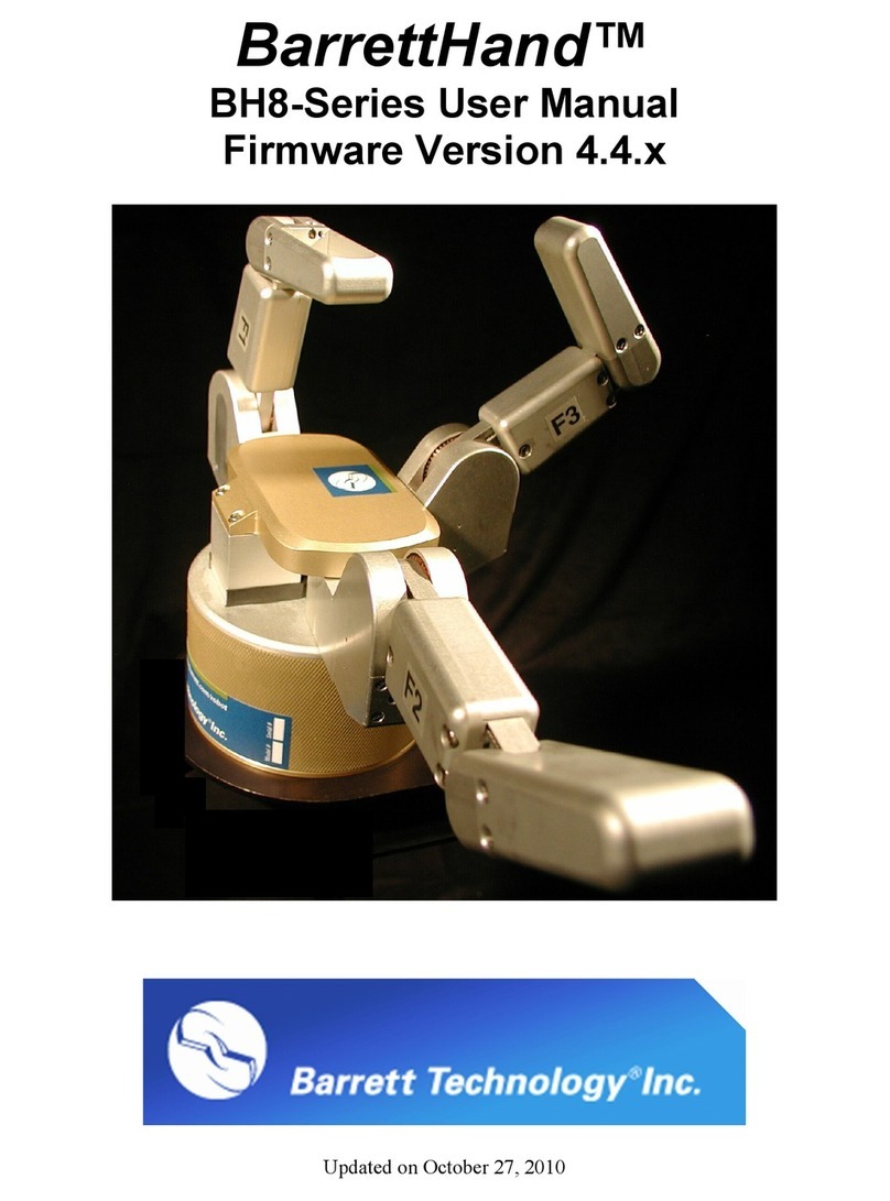
BarrettHand™
BH8-Series User Manual
Firmware Version 4.3x
Document: D3000
Version: AF.00


© 2007 Barrett Technology®, Inc. Document: D3000, Version: AF.00 Page 1 of 82
Table of Contents
TABLE OF CONTENTS............................................................................................................... 1
LIST OF FIGURES ....................................................................................................................... 3
LIST OF TABLES ......................................................................................................................... 4
LIST OF EQUATIONS................................................................................................................. 4
1
SYSTEM DESCRIPTION..................................................................................................... 5
1.1
STANDARD BH8-SERIES SYSTEM COMPONENTS............................................................. 5
1.1.1
System Features........................................................................................................ 5
1.1.2
Documentation......................................................................................................... 5
1.1.3
BarrettHand™.......................................................................................................... 6
1.1.4
Power Supply............................................................................................................ 7
1.1.5
Lab Bench Stand....................................................................................................... 8
1.1.6
Electrical Cables...................................................................................................... 8
1.1.7
Control Software and Firmware .............................................................................. 9
1.1.8
Maintenance Kit..................................................................................................... 10
1.2
SYSTEM OPTIONS............................................................................................................ 11
1.2.1
Arm adapter............................................................................................................ 11
1.2.2
C-Function Library ................................................................................................ 11
1.2.3
Strain gage Joint-Torque Sensors.......................................................................... 12
1.2.4
Control Software/Firmware Upgrades................................................................... 12
2
SAFETY AND CAUTIONS ................................................................................................ 13
3
SYSTEM SETUP ................................................................................................................. 14
3.1
MOUNTING METHOD 1: LAB BENCH STAND .................................................................. 14
3.2
MOUNTING METHOD 2: ON ROBOT ARM ....................................................................... 14
3.2.1
Robot-Arm Adapter ................................................................................................ 14
3.2.2
Installing the Hand Cable on a Robot Arm............................................................ 15
3.3
ELECTRICAL CONNECTIONS............................................................................................ 16
3.4
HOST COMPUTER ............................................................................................................ 16
3.5
INSTALLING BH8-SERIES CONTROL SOFTWARE........................................................... 16
3.6
POWER-UP SEQUENCE .................................................................................................... 16
3.7
DOWNLOAD FIRMWARE.................................................................................................. 17
4
CONTROL MODES – SUPERVISORY AND REALTIME ........................................... 17
5
SUPERVISORY CONTROL MODE................................................................................. 19
5.1
OVERVIEW ...................................................................................................................... 19
5.1.1
Commands.............................................................................................................. 19
5.1.2
Motor commands.................................................................................................... 19
5.1.3
Status Codes........................................................................................................... 19
5.2
COMMAND LIST .............................................................................................................. 20
5.2.1
Movement Commands ............................................................................................ 20
5.2.2
Motor parameter commands .................................................................................. 22
5.2.3
Global parameter commands................................................................................. 23
5.2.4
Administrative commands ...................................................................................... 25
5.2.5
Advanced commands.............................................................................................. 26
5.3
MOTOR PARAMETERS ..................................................................................................... 26

© 2007 Barrett Technology®, Inc. Document: D3000, Version: AF.00 Page 2 of 82
5.3.1
Movement ...............................................................................................................26
5.3.2
Status ...................................................................................................................... 28
5.3.3
RealTime.................................................................................................................29
5.3.4
Advanced ................................................................................................................ 31
5.4
GLOBAL PARAMETERS ....................................................................................................34
5.4.1
Configuration..........................................................................................................34
5.4.2
Status ...................................................................................................................... 34
5.4.3
Advanced ................................................................................................................ 35
5.5
TERMINATION CONDITIONS FOR MOVEMENT COMMANDS.............................................. 35
6
REALTIME CONTROL.....................................................................................................37
6.1
OVERVIEW ......................................................................................................................37
6.2
CONTROL AND FEEDBACK BLOCKS.................................................................................37
6.2.1
Control Blocks........................................................................................................38
6.2.2
Feedback Blocks.....................................................................................................38
6.2.3
Loop Feedback Delta Position ............................................................................... 39
6.3
PARAMETER SUMMARY................................................................................................... 39
6.4
EXAMPLE ........................................................................................................................41
7
MAINTENANCE .................................................................................................................41
7.1
FINGER CABLE PRETENSION............................................................................................ 41
7.2
FASTENER CHECK ...........................................................................................................44
7.3
LUBRICATION.................................................................................................................. 45
7.4
STRAIN GAGES ................................................................................................................49
8
TROUBLESHOOTING.......................................................................................................51
9
THEORY OF OPERATION...............................................................................................58
9.1
ELECTRONIC ARCHITECTURE ..........................................................................................58
9.2
LOW-LEVEL MOTOR CONTROL....................................................................................... 59
9.2.1
Trapezoidal Control ...............................................................................................59
9.2.2
Velocity Control...................................................................................................... 59
9.3
MECHANISMS..................................................................................................................60
9.3.1
TorqueSwitch™......................................................................................................60
9.3.2
Spread Motion ........................................................................................................ 64
9.4
OPTIONAL STRAIN GAGE JOINT-TORQUE SENSOR........................................................... 65
9.5
KINEMATICS....................................................................................................................67
9.6
JOINT MOTION LIMITS.....................................................................................................71
APPENDIX A
TECHNICAL SPECIFICATIONS .............................................................74
APPENDIX B
FAQ................................................................................................................76
APPENDIX C
GLOSSARY ..................................................................................................78
INDEX...........................................................................................................................................80

© 2007 Barrett Technology®, Inc. Document: D3000, Version: AF.00 Page 3 of 82
List of Figures
FIGURE 1-BARRETTHAND™ ........................................................................................................... 6
FIGURE 2-BARRETTHAND™BH8-SERIES NEW 24-VOLT POWER SUPPLY.................................... 7
FIGURE 3-LAB BENCH STAND ......................................................................................................... 8
FIGURE 4-CABLE CONNECTIONS ..................................................................................................... 9
FIGURE 5-ARM ADAPTER............................................................................................................... 11
FIGURE 6-LAB BENCH STAND WITH WIRE STRAIN RELIEF............................................................ 14
FIGURE 7-INSTALLING AN ARM ADAPTER..................................................................................... 15
FIGURE 8–HEX SET SCREW............................................................................................................ 42
FIGURE 9-PRETENSIONING THE TENDON CABLE ........................................................................... 43
FIGURE 10 -IMPORTANT FASTENER LOCATIONS............................................................................. 44
FIGURE 11 -LUBRICANT APPLICATION POINTS............................................................................... 46
FIGURE 12 -FINGER ATTACHMENT-SCREW LOCATION................................................................... 47
FIGURE 13 -REMOVING THE FINGERS FOR MAINTENANCE ............................................................. 47
FIGURE 14 -RESETTING THE FINGERTIP POSITION AFTER FINGER REMOVAL ................................. 48
FIGURE 15 -REATTACHING FINGERS AFTER MAINTENANCE........................................................... 49
FIGURE 16 -SHROUD REMOVAL ..................................................................................................... 50
FIGURE 17 -BALANCING POTENTIOMETER ..................................................................................... 50
FIGURE 18 -CABLE AND IDLER PULLEY.......................................................................................... 52
FIGURE 19 -MANUAL TORQUE SWITCH ACTIVATION..................................................................... 54
FIGURE 20 -MANUAL TORQUESWITCH™ACTIVATION DRIVE HOLES........................................... 55
FIGURE 21 –BARRETTHAND™CONTROLLER BLOCK DIAGRAM.................................................... 58
FIGURE 22 -BARRETT'S PATENTED TORQUESWITCH™MECHANISM ............................................. 60
FIGURE 23 -TORQUESWITCH™OPERATION................................................................................... 62
FIGURE 24 -BREAKAWAY FORCE CURVE ....................................................................................... 63
FIGURE 25 –STALLED FINGERTIP FORCE VS.COMMANEDED VELOCITY (MEASURED BEFORE
BREAKAWAY).......................................................................................................................... 64
FIGURE 26 -PINCH GRASP TORQUE ................................................................................................ 65
FIGURE 27 -STRAIN GAGE JOINT-TORQUE SENSOR........................................................................ 66
FIGURE 28 -STRAIN GAGE TORQUE CURVES.................................................................................. 67
FIGURE 29 -BARRETTHAND™IN ZERO POSITION.......................................................................... 68
FIGURE 30 -D-H FRAME ASSIGNMENT FOR GENERALIZED FINGER................................................ 69
FIGURE 31 -FINGER JOINT MOTION LIMIT RANGE........................................................................... 72
FIGURE 32 -SPREAD JOINT MOTION LIMIT RANGE.......................................................................... 73
FIGURE 33 -BARRETTHAND™DIMENSIONS .................................................................................. 75
FIGURE 34 –TORQUESWITCH™ACTIVATION GRAPH .................................................................... 77

© 2007 Barrett Technology®, Inc. Document: D3000, Version: AF.00 Page 4 of 82
List of Tables
TABLE 1-FIRMWARE FILE LIST......................................................................................................17
TABLE 2-MOTOR PREFIXES ...........................................................................................................19
TABLE 3-HAND STATUS CODES.....................................................................................................20
TABLE 4-REALTIME FINGER CONTROL PARAMETERS...................................................................40
TABLE 5-REALTIME GLOBAL CONTROL PARAMETERS..................................................................40
TABLE 6-LUBRICATION SCHEDULE................................................................................................45
TABLE 7-BARRETTHAND™MOTOR PROPERTIES..........................................................................59
TABLE 8-D-H PARAMETER VALUES FOR ALL FINGERS..................................................................68
TABLE 9-D-H LINK PARAMETERS FOR FINGERS............................................................................69
List of Equations
EQUATION 1-HOMOGENEOUS TRANSFORM BETWEEN {I-1}AND {I}.............................................67
EQUATION 2-FORWARD KINEMATICS FROM FINGERTIP TO WORLD...............................................68
EQUATION 3-FORWARD KINEMATICS FOR FINGER F1 ...................................................................70
EQUATION 4-MOTOR TO JOINT ANGLE TRANSFORM BEFORE TORQUESWITCH™ACTIVATION.....70
EQUATION 5-MOTOR TO JOINT ANGLE TRANSFORM AFTER TORQUESWITCH™
ACTIVATION ......71

© 2007 Barrett Technology®, Inc. Document: D3000, Version: AF.00 Page 5 of 82
1 System Description
1.1 Standard BH8-SERIES System Components
1.1.1 System Features
Thank you for choosing the BarrettHand™ Grasper™. The BarrettHand™ is designed to
overcome the inflexibility of conventional grippers with microprocessor-enabled dexterity while
maintaining durability, compactness, and ease of use. The BarrettHand™ is a multi-fingered
Grasper™ with the dexterity to secure target objects of different sizes, shapes, and orientations.
Rather than rely on pinching gripper friction or permanent gripper-jaw shape customization the
BarrettHand™ gently envelops the object, securely locking its joints until commanded to release.
System integration with any robotic arm is fast and simple. Even with its low, 1.2-kg, weight and
compact form, it is totally self-contained. The BarrettHand™ uses industry-standard serial
communications, which is the common denominator of communications, for guaranteed universal
compatibility. While the bandwidth of serial communications may limit less intelligent
equipment, the five (5) on-board microprocessors combined with Barrett’s open Grasper Control
Language (GCL) endows the BarrettHand™ with millisecond response.
The compactness and low weight of the BarrettHand™ assures that the enhanced dexterity does
not compromise arm payload. Its low mass and short base-to-grasp-center distance minimize joint
loading on the host robot and reduce extraneous arm movements during object reorientation. The
custom control-electronics package is contained entirely within the palm shell, reducing electrical
wiring to a single cable carrying all communications and motor power.
We hope that you enjoy the versatility and functionality of the BarrettHand™. Please never
hesitate to give feedback and to ask for advice as needed. US+617-252-9000,
<service@barrett.com>, or <http://www.barrett.com/robot/>.
1.1.2 Documentation
The baseline turnkey BarrettHand™ (without the optional C++ Function Library) comes with two
(2) manuals:
1. BH8-SERIES User Manual for setup and basic operation (this manual)
2. BHControl Interface Manual
The User Manual (this manual) covers:
This manual is up-to-date as of version 4.34 of the BarrettHand™ firmware.
•System components and options
•System setup and operation
•Maintenance
•Troubleshooting
•Theory of operation
•Technical specifications
•Frequently asked questions
The second manual is the BHControl Interface Manual for the BHControl Windows Interface,
which enables immediate functionality in 3 different ways ranging from easy and intuitive to
sophisticated. Refer to the BHControl Interface Manual for detailed instructions.
Both manuals come to you in printed form, electronic form on the Control Software CD ROM,
and in the customer-only section of the Barrett web site.

© 2007 Barrett Technology®, Inc. Document: D3000, Version: AF.00 Page 6 of 82
1.1.3 BarrettHand™
The BarrettHand™, shown in Figure 1, has three fingers labeled F1, F2 and F3. Two of the
fingers, F1 & F2, rotate synchronously and symmetrically about the base joint in a spreading
action. The “spread” motion around the palm allows “on-the-fly” grasp reconfiguration to adapt
to varying target object sizes, shapes, and orientations.
Aside from the spread motion, each of the three fingers on the BarrettHand™ feature two joints
driven by a single DC brushless servo motor. The joints of each finger are coupled through
Barrett’s patented TorqueSwitch™, which automatically switches motor torque to the appropriate
finger joint when closing on a target object. Using the fingers together allows the BarrettHand™
to "grasp" a wide variety of objects securely. The TorqueSwitch™ combined with the spread
function, makes object grasping nearly target-independent.
The BarrettHand™, shown in Figure 1, is equipped with a threaded base for compact and secure
mounting. The threaded base is fully compatible with the BarrettArm. And, with the arm adapter,
it can be mounted on virtually any robot with a standard ISO tool plate, for easy installation and
maintenance.
F1 and F2 Spread
around the Palm
F2 F1
F3
Onboard Control
Electronics Package in
Palm Shell
Threaded
Ring for
Quick
Connection
TorqueSwitch™
Shifts Torque to
Appropriate Finger
Joint
Figure 1 - BarrettHand™

© 2007 Barrett Technology®, Inc. Document: D3000, Version: AF.00 Page 7 of 82
1.1.4 Power Supply
The Power Supply for the BH8-SERIES, shown in Figure 2, can be plugged into any regular AC
power source. It provides DC motor bus power (24V), electronic component logic power (5V),
and supports RS-232 communications between the host computer (via the serial cable) and the
control electronics in the BarrettHand™ palm shell (via the Hand cable). This Power Supply
switches automatically to local voltage standards (95-130 & 190-260 VAC at 50-60Hz) around the
globe and contains built-in surge protection.
All three cables required to operate the BH8-SERIES connect to the Power Supply:
1. Line Cord supplying AC line voltage.
2. Serial Cable supporting RS-232 communications from the host computer.
3. Hand Cable which carries DC power and RS-232 to the BarrettHand™.
Figure 2 - BarrettHand™ BH8-SERIES new 24-Volt Power Supply

© 2007 Barrett Technology®, Inc. Document: D3000, Version: AF.00 Page 8 of 82
1.1.5 Lab Bench Stand
The bench mount stand for the BarrettHand™, shown in Figure 3, is ideal for off-arm
development. The durable Lexan® stand comes complete with cable management clips and
mounting features to hold your BarrettHand™ unit securely on any flat surface. Non-slip rubber
feet keep the stand from sliding during testing and programming.
Figure 3 - Lab Bench Stand
1.1.6 Electrical Cables
All necessary electrical cables are included in the basic BH8-SERIES System, shown in Figure 4.
An AC Line Cord connects the Power Supply to a wall source. A Serial Cable connects the Power
Supply and the host computer robot controller to establish the RS-232 communication link. The
Hand Cable connects the Power Supply to the BarrettHand™, supplying communications, logic
power, and motor power. This cable is durable and flexible, allowing the BarrettHand™ to be
used on any robot with minimal effect on robot performance. Use the included set of adhesive
guide clips for cable management. Since the control electronics reside inside the BarrettHand™
itself, no other electrical cabling is required.

© 2007 Barrett Technology®, Inc. Document: D3000, Version: AF.00 Page 9 of 82
Figure 4 - Cable Connections
1.1.7 Control Software and Firmware
The BH8-SERIES System control software consists of:
1. BHControl Interface application software,
2. Firmware (*.s19 software), and
3. Example programs.
Included with the software in electronic form are:
1. BHControl Interface Manual and
2. BH8-SERIES User Manual (this manual)
The BarrettHand™ has firmware that resides on the control electronics inside the palm. The
firmware requires only ASCII characters sent over a standard serial port. You build the character
strings to create the desired commands. The firmware then interprets the commands sent and
controls the motors, sets and retrieves parameters, or reads and writes to the EEPROM. See
Sections 4 and 6 for more information on firmware commands and parameters.

© 2007 Barrett Technology®, Inc. Document: D3000, Version: AF.00 Page 10 of 82
The BHControl Interface is a Windows application that allows you to control the BarrettHand™
quickly and easily. The BHControl Interface shows how to measure communication loop rates,
demonstrate functionality, test Supervisory and RealTime control sequences, and how to save
those sequences as ASCII text or even as C++ code (literally with the click of a “Generate C++
Code” button). See the BHControl Interface Manual for more information on the
Windows95/98/NT/2000-based BHControl Interface GUI.
1.1.8 Maintenance Kit
Included in each BarrettHand™ package is a maintenance kit. Use the maintenance kit in
accordance with the instructions in Section 7. The maintenance kit includes the following:
•1.0-mm Hex wrench
•1.27-mm Hex wrench
•2.0-mm Hex wrench
•Mobil 1® Lubricant in syringe
•Lubricant applicators
•Torque wrench
•2.0-mm Hex adapter for Torque wrench
•Loctite 222

© 2007 Barrett Technology®, Inc. Document: D3000, Version: AF.00 Page 11 of 82
1.2 System Options
1.2.1 Arm adapter
Barrett Technology provides an arm adapter (Figure 5) matching the make and model of any robot
specified by the customer. This lightweight arm adapter is made to work with the end-effector
bolt pattern on your robot, allowing quick, easy mounting and wire management for a BH8-
SERIES System. The arm adapter is bolted to the end of the robot arm and the BarrettHand™ is
secured to the arm adapter with its standard threaded locking ring. The arm adapter is also
equipped with an anti-rotation feature to prevent rotation during operation.
Arm Adapter
Figure 5 - Arm adapter
1.2.2 C-Function Library
The BarrettHand™ C-Function Library is a helpful tool for programming the BarrettHand™ using
the C language on IBM-compatible PC’s without having to manage serial communication and
timing issues. The library contains easy-to-use functions that permit the use of Supervisory and
RealTime commands in software routines developed by the end user. All of the functions are
available when the library is linked to the program. The C-Function Library also includes a
manual that describes all of the functions in detail and gives examples.
The C-Function Library is written in C++ and compiled for Windows 95/98/NT/2k. It is a typical
C++ library, providing a class Bhand from which you derive one object and use it for all
communications. The library uses a multithreaded mechanism for accessing the serial port, which
allows both synchronous and asynchronous access to the low-level thread and ensures that all
serial communications are executed with high priority. The low-level thread manages all input
and output buffers and makes controlling the BarrettHand™ easy.

© 2007 Barrett Technology®, Inc. Document: D3000, Version: AF.00 Page 12 of 82
1.2.3 Strain gage Joint-Torque Sensors
Barrett Technology offers a factory-installed torque sensor for the BH8-SERIES System. This
sensor measures the torque externally applied about the distal joint over a range of +/- 1 N-m.
This option uses strain gages to measures the differential tension in the “tendon” running through
each finger to the second joint. The information is processed in additional onboard circuitry when
this option is installed, it is accessed by requesting the present strain gage parameter. The strain
gage parameter represents the amount strain on the strain gage sensors. The strain gage values can
be calibrated by the customer to relate strain to joint torque. See Section 9.4 for more detailed
information on how the sensor works.
1.2.4 Control Software/Firmware Upgrades
Barrett Technology makes software and firmware upgrades periodically. Upgrades are available
for purchase or free of charge for customers of Barrett's subscription service. Refer to Barrett's
enclosed Warranty and Subscription Service Policy for more information.

© 2007 Barrett Technology®, Inc. Document: D3000, Version: AF.00 Page 13 of 82
2 Safety and Cautions
PLEASE READ THIS SECTION IN ITS ENTIRETY BEFORE USING YOUR
BARRETTHAND™.
Following these safety instructions will help prevent user injury and equipment damage.
•As with any piece of robotic equipment, it is ultimately up to you to be aware of your
surroundings during robot operation. The workspace of the system comprising the
BarrettHand™ and robot arm should be clearly marked to prevent persons or objects from
inadvertently entering the equipment’s reach. Before attaching the BarrettHand™, test host
robot trajectories to confirm that it will not inadvertently collide with other objects in the
workspace.
•NEVER connect or disconnect any electrical cables while the Power Supply is turned on.
Failure to follow this instruction could impart irreparable damage to the onboard electronics
or put you at risk of electrical shock.
•Always plug the Power Supply into a properly grounded wall source. Failure to do so could
damage the BarrettHand™ electronics and put you at risk of electrical shock.
•Do not place any part of your body or delicate objects within the grasp of the BarrettHand™
without first verifying control of the unit and confirming appropriate force levels.
•Do not allow the BarrettHand™ to be exposed to liquids that may cause electrical short-
circuit and put you at the risk of electrical shock.
•Keep dirt away from the exposed gear and cable drives located at the joints.
•Do not exceed the load limit of the fingers, 2 kg per finger. Consider all loading situations
including accelerated loads, cantilever loads from long objects, robot collisions, active loads,
etc.
•On models before the BH8-260: a portion of the onboard control electronics is exposed
through the base of the BarrettHand™. Before installing pre-BH8-260 models to a robot arm,
take necessary precautions to protect the electronics from impact, contaminants and static
discharge. Do not rest the BarrettHand™ unit directly on its base. Use the included lab
bench stand during standalone operation.
•Remove/replace the fingers only as instructed in Section 7.3.
•Monitor the operating temperature of the BarrettHand™ so that it does not exceed 65C.
Under normal conditions, the Hand operates between 40 and 60C. The BarrettHand™ was
designed with non-backdrivable finger joints to take advantage of the motors’ peak operating
performance in short bursts. The spread, however, is backdrivable to aid in target-
independent grasping (see Section 0) and requires constant motor current to actively hold
position. Idling the spread motor, when possible, will help keep the temperature lower.

© 2007 Barrett Technology®, Inc. Document: D3000, Version: AF.00 Page 14 of 82
3 System Setup
3.1 Mounting Method 1: Lab Bench Stand
The Lexan Bench Stand you received with the BarrettHand™ has been provided for convenience
in programming the BarrettHand™ when a host robot arm is not available. Use the wire guide
clips to provide strain relief to the Hand cable. Figure 6 illustrates how to mount the Hand in the
Lexan Bench Stand.
a) place base on Hand b) attach threaded ring c) attach Hand cable
d) screw in 2 retainer screws e) open cable clips f) secure all 3 clips
Figure 6 - Lab Bench Stand with Wire Strain Relief
Use the 2-mm hex wrench to open fingers 1,2, &3. Then, spread fingers to roughly 120 degrees
and rest the unit on its fingertips. Place the stand, feet up, onto the hand. Note the alignment of
the BarrettHand™ relative to the wire strain relief clips to ease connection of the BarrettHand™
Cable.
Make sure the Power Supply is turned OFF, and then route the BarrettHand™ Cable through all
three cable clips on the lab bench stand and plug it into the BarrettHand™. Tighten the cable clips
to hold the cable in place.
3.2 Mounting Method 2: On Robot Arm
3.2.1 Robot-Arm Adapter
Like the Lexan Bench Stand, the Robot Arm Adapter is made to secure the BarrettHand™ in place
and to provide strain relief to the Hand cable as shown in Figure 7. The Arm Adapter is fabricated
for the tool-plate of your specific robot arm and is designed for low-profile, rigidity, and low
weight.
To mount your BarrettHand™ on a robot, bolt the arm adapter onto the tool-plate bolt circle,
located at the end tip of the robot arm. Next, insert the threaded base of the BarrettHand™

© 2007 Barrett Technology®, Inc. Document: D3000, Version: AF.00 Page 15 of 82
through the hole in the arm adapter shown in Figure 7 aligning the indexing tab on the arm adapter
to the mating alignment slot on the BarrettHand™.
Secure the BarrettHand™ by threading the locking ring (included with your system) onto the base
of the BarrettHand™. Note that, depending on the details of your robot arm, you may need to
loosen the locking ring when installing the Hand cable the next Section.
Figure 7 - Installing an Arm Adapter.
3.2.2 Installing the Hand Cable on a Robot Arm
All of the power and communications for the BarrettHand™ have been consolidated into a single
high-durability robot cable which has a 15-pin connector at the Power Supply end and a tiny 10-
pin connector at the Hand end. To accommodate the complex motions of a robot arm, the
BarrettHand™ Hand Cable is extremely flexible and has been designed for compatibility with
both internal and external mounting schemes. When a robot arm does provide an internal channel,
the cross-section of the channel is tightly constrained. Therefore the Hand cable has been made
with a particularly tiny connector at one end to ease internal installation. The base of the Hand
Adaptor includes an opening to accommodate direct access from an internal cable to the back of
the BarrettHand™.
For external installation, plan to route the Hand Cable close to the center of each joint. Each
segment will need enough slack to accommodate the most extreme motions but not so much that
the cable might become snagged. Mount the cable clips to flat, dry, and clean link surfaces at
strategic points along the robot arm. Clean cable clip attachment areas with alcohol before
attaching via the self-adhesive backings. Place the BarrettHand™ Hand Cable loosely through the
cable retaining clips on the robot and the Arm Adapter. Move the robot arm through all of its
motion extremes to verify that the cable slack is adequate in each segment and that it will not snag.
Once verified, tighten the cable clips to secure the cable in place.

© 2007 Barrett Technology®, Inc. Document: D3000, Version: AF.00 Page 16 of 82
3.3 Electrical Connections
•Place the Power Supply on a flat, secure surface anywhere between the base of the robot and
the host PC (or robot controller).
•With your PC off, attach the serial cable from your 9-pin COM Port to the Power Supply.
Barrett Technology supplies a 3-meter standard straight-through serial cable, but you may
purchase a longer cable if desired.
•Attach the Power Supply Line Cord into any convenient outlet and verify that it is switched
OFF.
•Attach the 15-pin end of the Hand Cable to the Power Supply and the other end into the Hand.
Tighten the strain-relief screws using the Phillips screwdriver provided in the toolkit.
3.4 Host Computer
The BH8-SERIES Control Software was written for computers running Windows
95/98/NT4.0/2000. Barrett Technology recommends using a Pentium based processor with a
minimum CPU clock speed of 266 MHz and 32 Mbytes of RAM. The software requires 10
Mbytes of free disk space. Communications requires one available 9-pin serial port.
3.5 Installing BH8-SERIES Control Software
The BH8-SERIES Control Software consists of the BHControl Interface, firmware, and example
programs. The BHControl Interface is a graphical Windows interface that allows you to control
the BarrettHand™ quickly and easily. The BHControl Interface can be used to test Supervisory
and RealTime control sequences, determine communication loop rates, demonstrate functionality,
help you learn how to independently write C code, and automatically generate C code based on
tested algorithms
1
. Run the setup.exe program on the CD-ROM to install all necessary files for
using the BHControl Interface, the most recent version of firmware, online manuals, and example
programs.
3.6 Power-Up Sequence
Once the previous steps are complete, your BH8-SERIES System is ready for use. Power up the
system according to the instructions below:
1. Verify the serial cable is plugged into the desired communications port and into the 9-pin
connector on the back of the Power Supply.
2. Verify the BarrettHand™ Cable is plugged into the 15-pin connector on the back of the Power
Supply and into the bottom of the BarrettHand™.
3. Verify the AC line Line Cord cord is plugged into a valid power source (see Appendix A) and
into the power outlet on the back of the Power Supply.
4. Turn on the host computer.
5. Turn on the Power Supply. The main power switch is located on the back panel.
6. The BarrettHand™ is now ready for operation.
1
The code generated by the Control Interface requires the C-Function Library to compile.

© 2007 Barrett Technology®, Inc. Document: D3000, Version: AF.00 Page 17 of 82
.
3.7 Download Firmware
The BarrettHand™ firmware resides on board the electronics located inside the Hand. This
firmware is stored in RAM that receives its power from the Power Supply when the system is
turned on and from an embedded super capacitor when powered down. This super capacitor is
designed to maintain the firmware in RAM for two days. However, especially in humid weather,
the memory will begin to degrade after two days and eventually will be cleared. Since degraded
memory may result in erratic control, please reload firmware if the hand has been turned off for
several days.
When the firmware has been cleared or degraded, it will need to be reinstalled. The download
process takes only a few minutes, as follows:
1. Verify the BarrettHand™ is plugged into the Power Supply.
2. Verify the host computer is plugged into the Power Supply.
3. Verify the Power Supply is attached to a power source and turned on.
4. Run the BHControl Interface program BHControl.exe.
5. Press the Start Download button
6. Open the appropriate file according to Table 1.
7. Cycle power: Switch the Power Supply off, wait 5 seconds, then turn it back on. The
download begins automatically.
8. After downloading the file, the BarrettHand™ is ready for operation.
9. Initialize the software by pressing the Initialize Library button.
Table 1 - Firmware File List
File Name Description
BarrettHand™ Firmware
v4_33.S19 Version 4.33 Firmware with RealTime
mode capabilities.
4 Control Modes – Supervisory and RealTime
The BarrettHand™ can be used in either of two (2) modes:
1. high-level Supervisory mode or
2. low-level RealTime mode.
Most users of the BarrettHand™ can rely exclusively on Supervisory mode since it handles
virtually every function of the BarrettHand™. Supervisory mode leverages the Motorola
microprocessor onboard the Hand. This processor interprets incoming Supervisory Commands
and then applies control signals across the set of four (4) motion-control microprocessors.
Supervisory mode allows you to command individual or multiple motors to close, open, and move
to specific positions; it also provides for setting the various configuration parameters and reporting
positions and torques (torque measurement requires optional strain-gage sensors).
At the simplest level, Supervisory mode allows you to type and receive ASCII text characters on a
terminal (using any type of computer hardware or operating system, such as UNIX, Macintosh,
PalmPilot, and proprietary robot controllers, etc.). To automate grasping applications, you can
write programs, scripts, or macros that send and receive these text characters through the serial
port (e.g. the optional BarrettHand™ C-Function Library).
RealTime mode extends the capability of Supervisory mode. Sometimes users may wish to
bypass the Supervisory functions and apply control directly to the motion-control
microprocessors. RealTime mode enables users to close control loops in real time from their host
PC or robot controller. This benefits users interested in real-time control via a data-glove,

© 2007 Barrett Technology®, Inc. Document: D3000, Version: AF.00 Page 18 of 82
PhanTom, visual-servoing applications, real-time force control (via optional strain-gage sensors),
etc. Users can switch between Supervisory and RealTime modes on-the-fly as desired, allowing
for mixed mode operation.
If you use the BHControl Interface GUI software that runs on Windows-based PCs, you will likely
wish to experiment with the “Visual” control window to familiarize yourself with the
BarrettHand™. The Visual window relies exclusively on RealTime control mode since it must
follow your RealTime mouse-cursor movements.
Other manuals for BH8 Series
1
Table of contents
Other Barrett Robotics manuals


