Garmin Force Trolling Motor 50" Service manual

© 2020 Garmin Ltd. or its subsidiaries. All rights reserved.
Service Alert 2078 22 June 2020 Page 1 of 76
SERVICE ALERT
‹
FORCE TROLLING MOTOR
SERVICE ALERT....................................................................................... 2
ALERTE DE SERVICE .............................................................................. 6
AVVISO DI SERVIZIO ............................................................................. 11
SERVICE-WARNUNG ............................................................................. 16
ALERTA DE MANTENIMIENTO ............................................................. 21
ALERTA DE SERVIÇO............................................................................ 26
SERVICEWAARSCHUWING .................................................................. 31
SERVICEMEDDELELSE......................................................................... 36
HUOLTOHÄLYTYS ................................................................................. 40
TJENESTEVARSEL ................................................................................ 44
SERVICEMEDDELANDE ........................................................................ 49
ALERT SERWISOWY.............................................................................. 53
SERVISNO OPOZORILO ........................................................................ 58
SERVISNO UPOZORENJE..................................................................... 63
服务快讯................................................................................................... 68
サービスアラート..................................................................................... 72

© 2020 Garmin Ltd. or its subsidiaries. All rights reserved.
Service Alert 2078 22 June 2020 Page 2 of 76
‹
SERVICE ALERT
FORCE TROLLING MOTOR
PRODUCTS AFFECTED
Force Trolling Motor, 50” and 57” models.
ISSUES
This service alert contains information regarding three issues that may affect your Garmin Force Trolling Motor.
Issue 1: Unexpected boat movement
Issue 2: Under-tightened power cable
Issue 3: Safety strap reminder and new latch kit
WARRANTY INFORMATION
Customers: You can resolve these issues by following the directions below, or an authorized Garmin dealer or service
center can resolve these issues under warranty.
Dealers: Garmin will reimburse up to 1 hour of labor to resolve these issues.
ISSUE 1: UNEXPECTED BOAT MOVEMENT
Garmin has received a small number of reports indicating the Force Trolling Motor may move the boat unexpectedly and
quickly when the anchor lock feature is engaged This can be caused by 1) the coil cable being tightly compressed
between the steering housing and the shaft cap, or 2) the motor shaft being out of alignment.
ISSUE 1 COMPLIANCE
Mandatory
ISSUE 1 RESOLUTIONS
1) Possible Compression of the Coil Cable
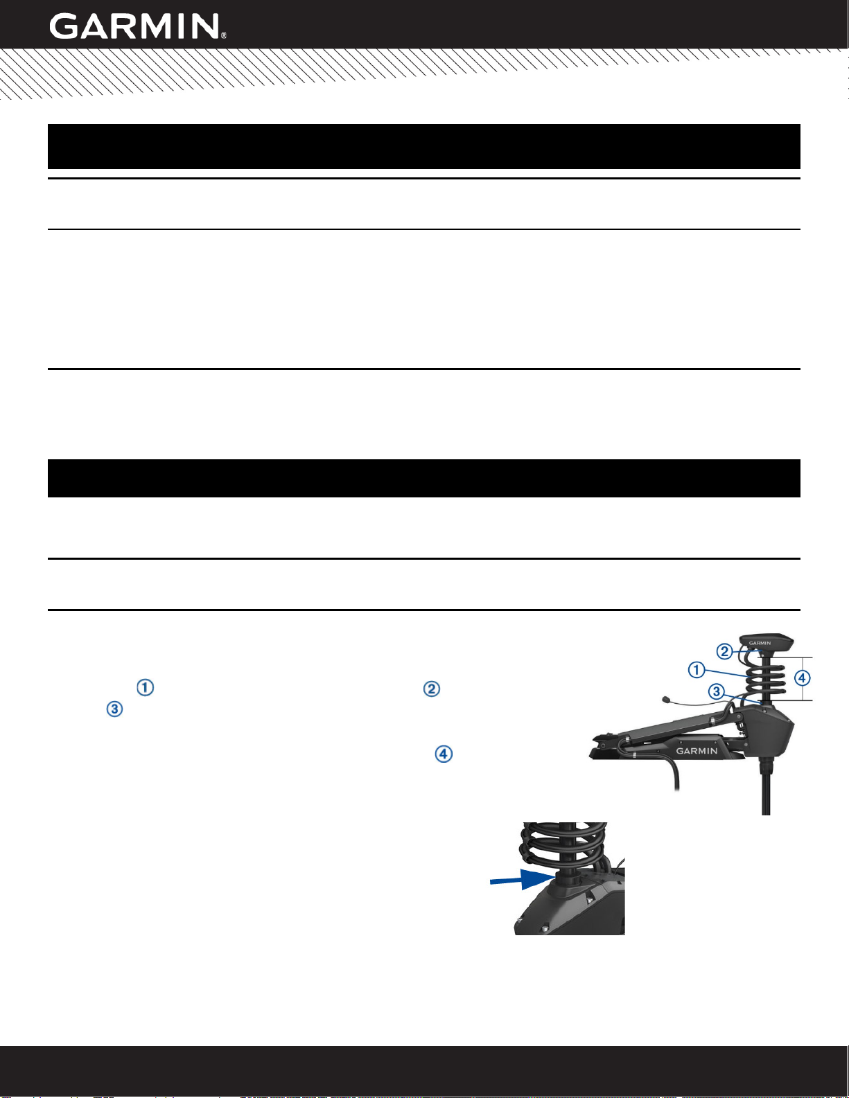
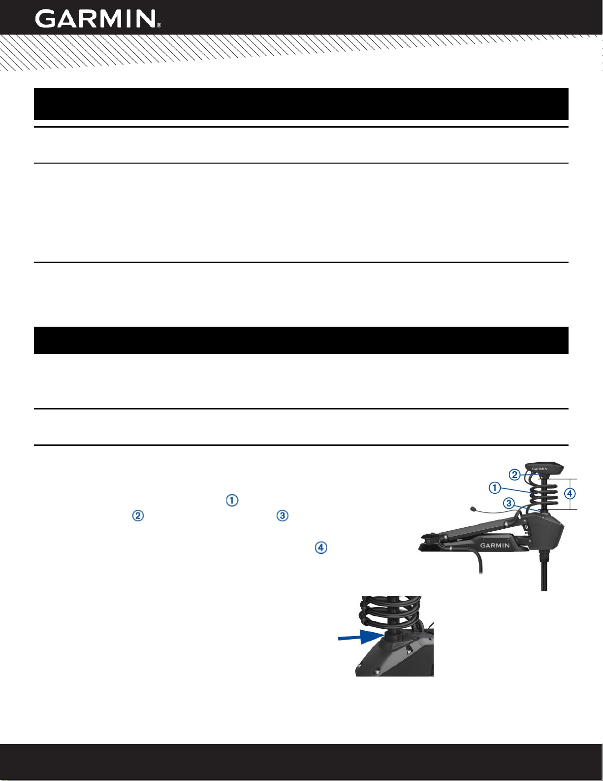
When setting the depth of the Force Trolling motor, you must avoid setting it so that
the coil cable is compressed between the shaft cap and the steering housing
. The coil cable must move freely when the motor steers.
To verify the safe max depth setting , the distance from the bottom of the shaft cap
to top of the bushing on the steering housing should not be less than 4 in (10 cm).
2) Possible Motor Shaft Misalignment
Perform these tests to verify proper motor shaft alignment.
Visually Inspect the Top Bushing for Cracks
If the bushing is cracked or is disconnected from the steering
housing, the motor shaft could be misaligned. Send an email to
MarineServiceAlerts@garmin.com for further information.
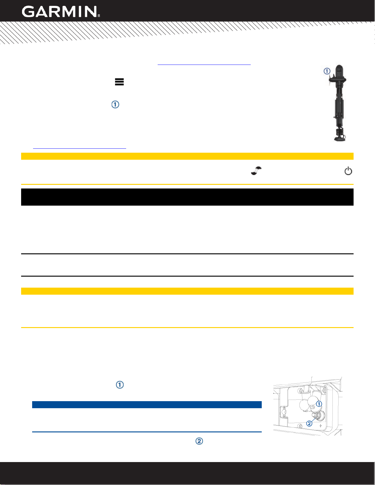
Observe the Stowing Direction of the Propeller
1. On the remote control, select >Settings > Trolling Motor > Prop Stow Side and note the direction
the propeller is configured to stow.
NOTE: Right and left are determined by viewing the trolling motor from behind.
2. Transition the trolling motor from the deployed to the stowed position and observe the behavior of the
motor.
If the motor automatically turns to any direction other than the side you noted in step 1, the motor shaft
could be misaligned. Send an email to MarineServiceAlerts@garmin.com for further information.
© 2020 Garmin Ltd. or its subsidiaries. All rights reserved.
Service Alert 2078 22 June 2020 Page 3 of 76
‹
SERVICE ALERT
CAUTION
Always keep the remote control on your person when using the trolling motor. If the operation of the trolling motor needs
to be changed or stopped at any time, you can press on the remote control, press on the foot pedal, or press on
the mount to stop the propeller.
ISSUE 2: UNDER-TIGHTENED POWER CABLE
Garmin has determined the nuts on the power terminals of the trolling motor may not be fully tightened. In certain
situations, this can cause heat to build up on the power cable, which could lead to a brief electrical fire on the wire
insulation. As mandated in the Force Trolling Motor Installation Instructions, you must install a proper circuit breaker,
which can limit heat buildup after the breaker trips. It should also be noted that the wire insulation is flame retardant and
self-extinguishing. These factors help limit the scope and duration of any potential brief electrical fire.
ISSUE 2 COMPLIANCE
Mandatory
ISSUE 2 RESOLUTION
CAUTION
You must disconnect the motor from the battery before servicing the trolling motor to avoid causing an electrical short.
When stowing or deploying the motor and when working on the power-cable terminals, be aware of the risk of entrapment
or pinching from moving parts, which can result in injury.
Tightening the Power Cable Connection without Disassembly
If the trolling motor installation allows enough room to access the power cable connection on the steering system using a
10 mm socket, you can follow these instructions to tighten the nuts. The estimated time to complete this service is
approximately 5 minutes.
1. Disconnect the trolling motor from power.
2. Transition the trolling motor to the deployed position.
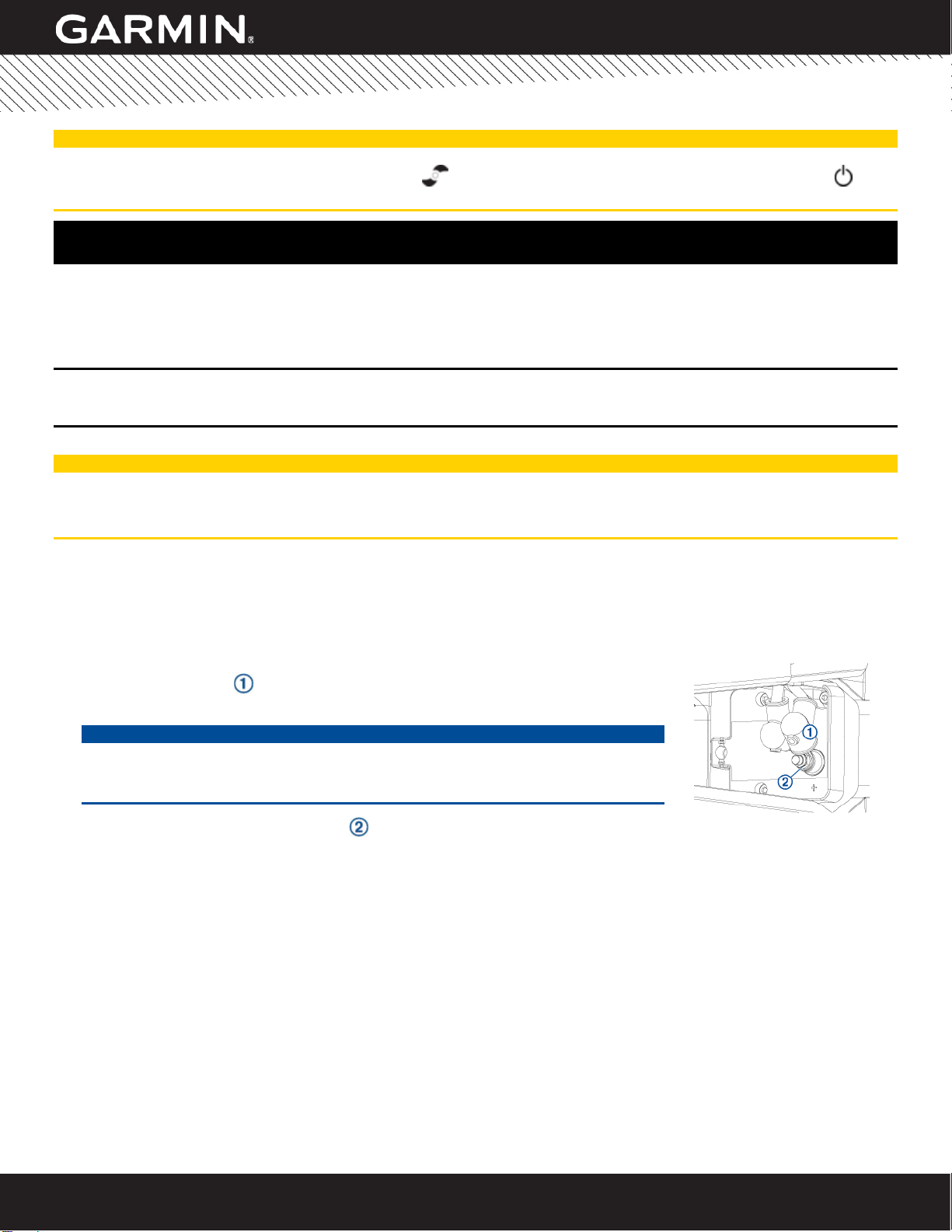
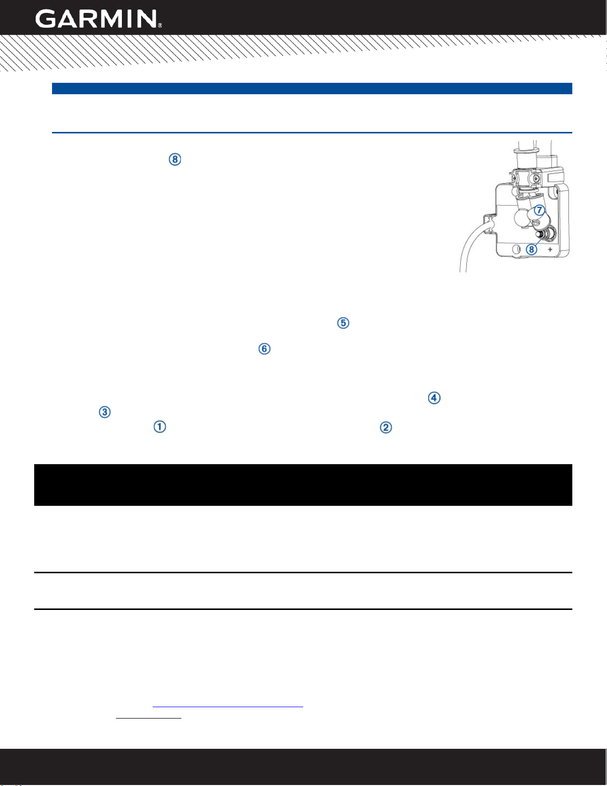
3. Pull the rubber shield up and away from the positive terminal on the steering
servo housing.
NOTICE
Do not overtighten the nuts that secure the power cable. The nuts should be snug
and securely clamp the ring terminal on the power cable, but excessive tightening
may damage the connection.
4. Using a 10 mm socket, tighten the nut that secures the power cable to the positive terminal, observing the
following considerations:
•A properly tightened nut will have no gap between the ring terminal on the power cable, the nut, and the
washer, and you will not be able to move the ring terminal on the post.
•If you have a torque wrench (recommended), you should tighten the nuts to 3 ft-lbs (36 in-lbs) (4 N-m).
5. Pull the rubber shield down to cover the positive terminal.
6. Repeat steps 3 through 5 for the negative terminal.
7. Reconnect the trolling motor to power.
Tightening the Power Cable with Minimal Disassembly
In some cases, the mounting location or other factors may make it difficult to access the power cable connection on the
steering system using a 10 mm socket to tighten these connections. In this situation, you can follow these instructions to
partially disassemble the motor and tighten the nuts. The estimated time to complete this service is approximately 15
minutes.

© 2020 Garmin Ltd. or its subsidiaries. All rights reserved.
Service Alert 2078 22 June 2020 Page 4 of 76
‹
SERVICE ALERT
1. Disconnect the trolling motor from power.
2. Transition the trolling motor to the deployed position.
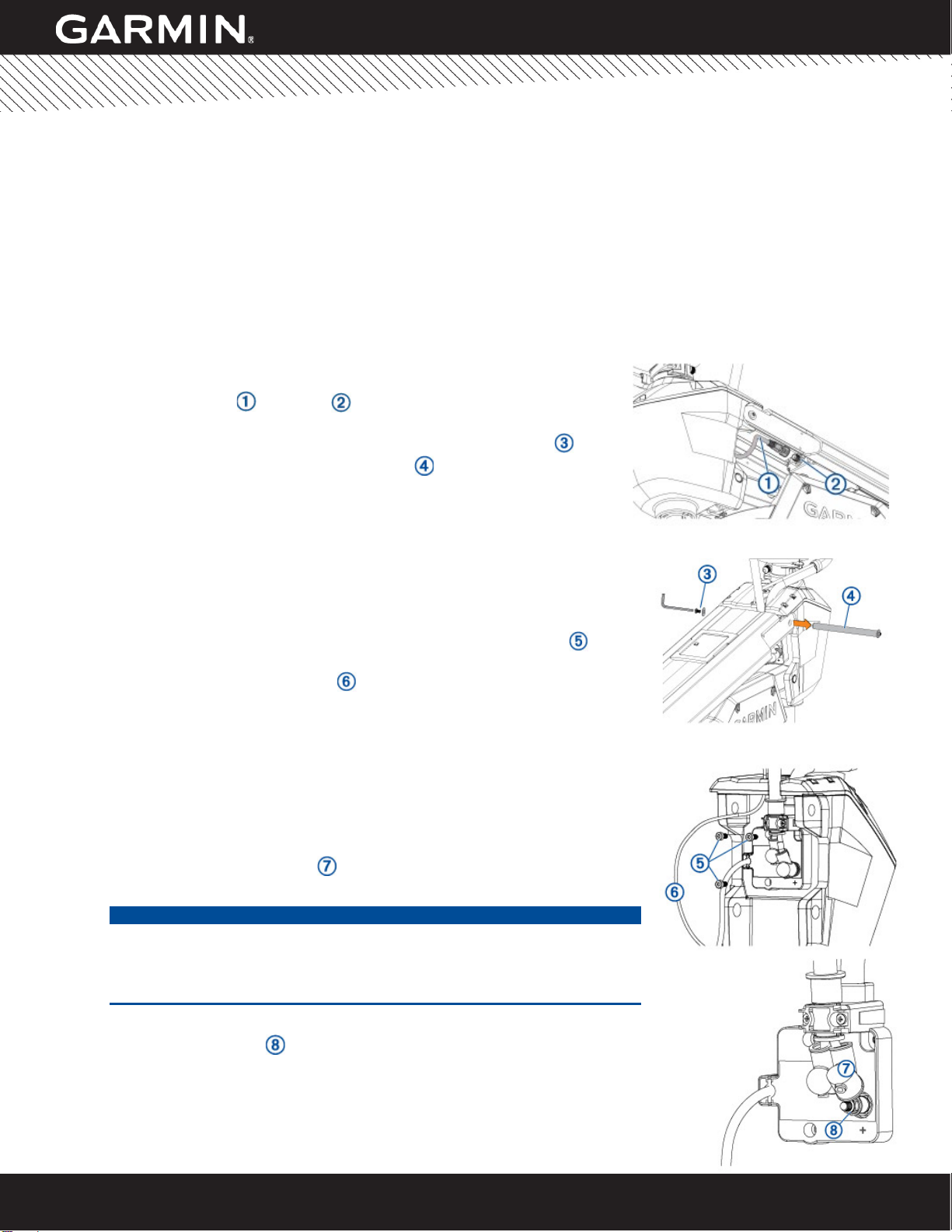
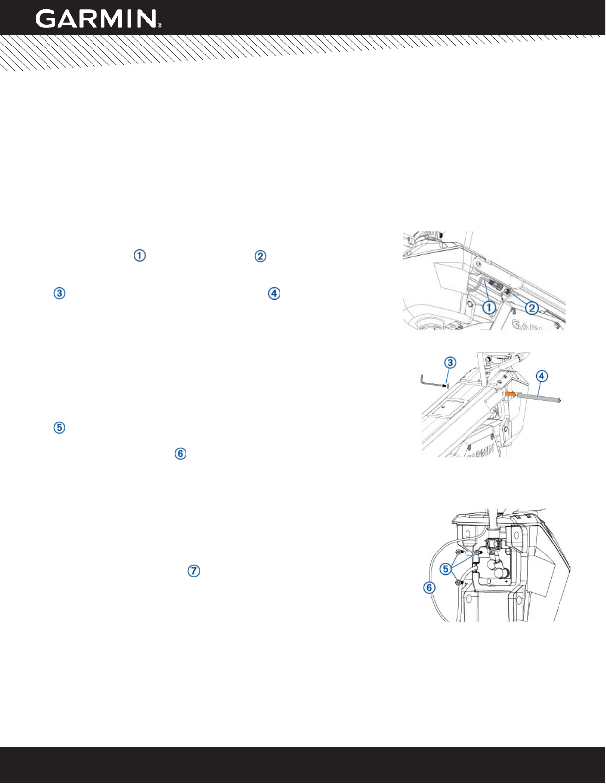
3. Disconnect the cable from the display panel on the upper link of the
mount by turning the collar on the connector counter-clockwise.
4. Using two 4 mm hex bits or wrenches, remove a screw and washer
from one side of the upper pin on the steering system housing.
NOTE: When you remove this pin, the upper link of the mount will
drop, and the steering system housing may tip forward. Make sure
you are prepared for this movement.
The bushings between the steering system housing and upper link of the
mount may fall out when you remove this pin. Make sure you retain these
bushings.
5. Using a 4 mm hex bit or wrench, remove the three screws that secure the
cable-junction box to the steering system housing.
6. Create slack in the pull cable and move it to the side so that it is not lying
across the cable-junction box.
7. Tip the steering system housing forward and pull the cable-junction box away
from the housing to disconnect it.
NOTE: The cable-junction box is connected to the steering system housing
with a multi-pin connector. You will encounter slight resistance when you
pull on the box.
8. Move the cable-junction box into a position where you can access the power
cable terminals.
9. Pull the rubber shield up and away from the positive terminal on the steering
servo housing.
NOTICE
Do not overtighten the nuts that secure the power cable. The nuts should
be snug and securely clamp the ring terminal on the power cable, but
excessive tightening may damage the connection.
10. While holding the cable-junction box in your hand, use a 10 mm wrench to tighten the
nut that secures the power cable to the positive terminal, observing the following:
•A properly tightened nut will have no gap between the ring terminal on the
power cable, the nut, and the washer, and you will not be able to move the
ring terminal on the post.
•If you have a torque wrench (recommended), you should tighten the nuts
to 3 ft-lbs (36 in-lbs) (4 N-m).
11. Pull the rubber shield down to cover the positive terminal.
12. Repeat steps 9 through 11 for the negative terminal.
13. Tip the steering system housing forward, align the connector on the back of the cable-
junction box with the connector on the steering system housing, and press to connect
it.
14. Secure the cable-junction box to the steering system housing using the three screws
you removed in step 5.
15. Remove the slack from the pull cable and make sure it is not pinched or tangled in the power or display panel
cables. The pull cable should run vertically along the steering system housing without any kinks or bends.
16. Make sure the bushings are installed in the steering system housing and reconnect the upper link of the mount to the
steering system housing using the pin , washer, and screw you removed in step 4.
17. Align the cable with the keyed connector on the display panel and turn the collar clockwise to secure it.
18. Reconnect the trolling motor to power.

© 2020 Garmin Ltd. or its subsidiaries. All rights reserved.
Service Alert 2078 22 June 2020 Page 5 of 76
‹
SERVICE ALERT
ISSUE 3: SAFETY STRAP REMINDER AND NEW LATCH KIT
The safety strap included with your Garmin Force Trolling Motor must be secured when the trolling motor is in the stowed
position and the vessel is underway or being towed. Failure to secure the safety strap may allow the trolling motor to
deploy, particularly at higher speeds in rough water. If the trolling motor deploys while the vessel is moving, it may cause
damage to the trolling motor and increase drag on the vessel.
ISSUE 3 COMPLIANCE
Recommended
ISSUE 3 RESOLUTION
You can install a latch kit to increase the rigidity of the latch system in rough conditions while the motor is in the stowed
position. The latch kit does not remove the requirement to secure the included safety strap.
If your trolling motor was purchased after June of 2020, the latch kit may already be installed. You can determine whether
the kit is already installed by comparing your motor to the photos below.
Send an email to MarineServiceAlerts@garmin.com to request a latch kit for your motor. You must include the serial
number (located on the back of the steering housing below the cable-junction box, appearing as s/n: 5RXXXXXXX).
Securing the Safety Strap
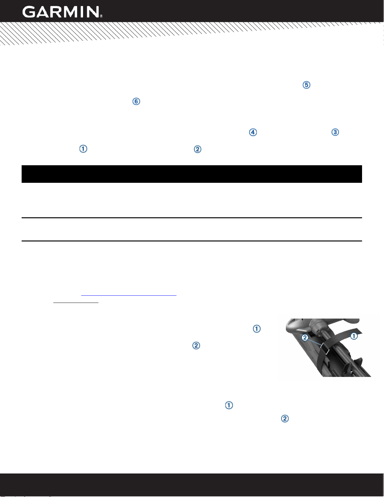
1. With the motor in the stowed position, lift the long end of the strap over the top
of the motor.
2. Feed the end of the strap through the buckle on the other end of the strap.
3. Pull the strap through the buckle until it holds the motor securely to the mount.
4. Pull the strap away from the buckle and push down to fasten it to the other side of
the strap.
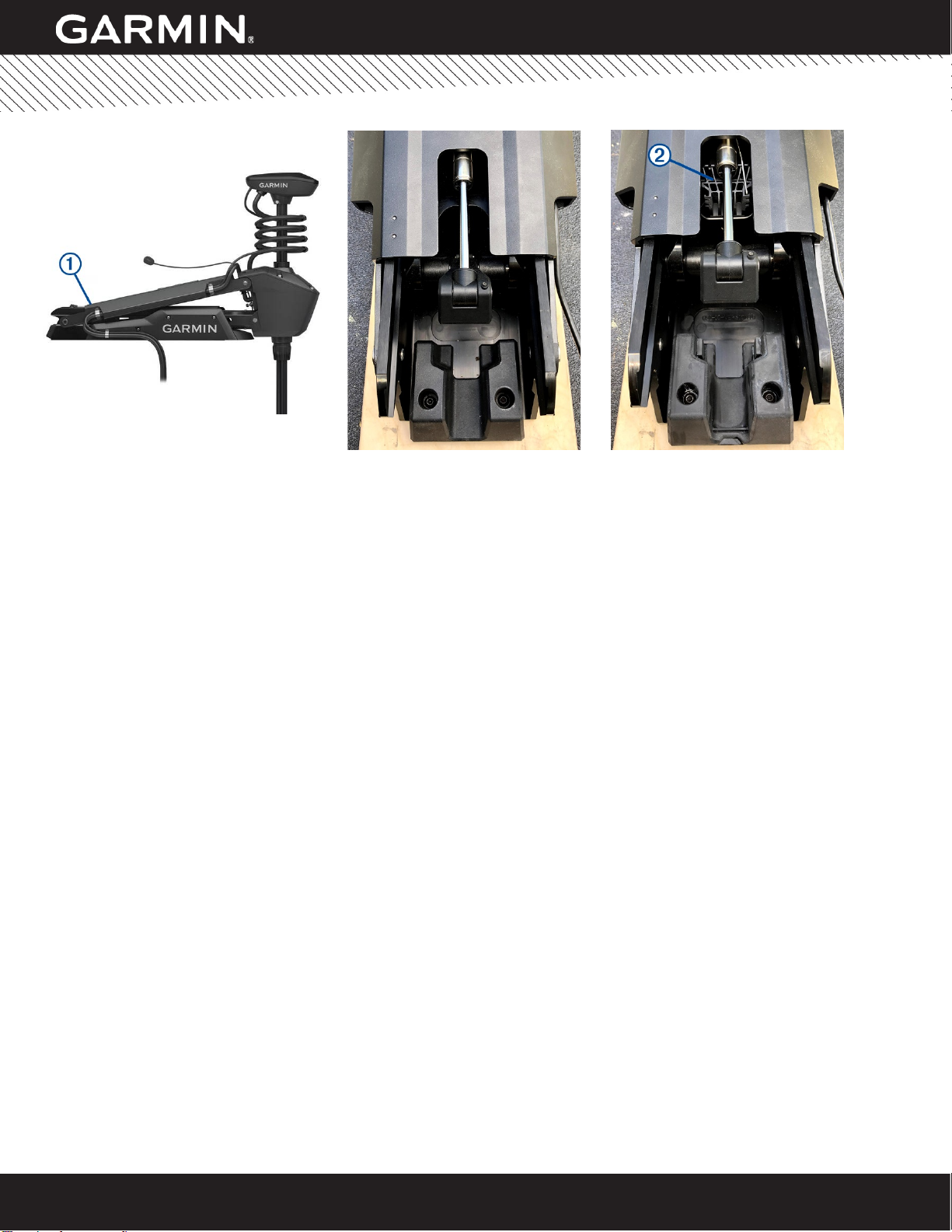
Determining Whether or Not the Latch Kit is Installed on Your Motor
1. Place the trolling motor into the deployed position.
2. Examine the space below the gas spring at the end of the mount .
If your motor has the kit installed, you can see the additional bracket located below the gas spring.
Motor with the Kit
Installed
Motor without the Kit
Installed
© 2020 Garmin Ltd. ou ses filiales. Tous droits réservés.
Alerte de service 2078 22 juin 2020 Page 6 sur 76
‹
ALERTE DE SERVICE
MOTEUR ELECTRIQUE FORCE
PRODUITS CONCERNÉS
Moteur électrique Force, modèles 50” et 57”.
PROBLEMES
Cette alerte de service contient des informations concernant trois problèmes susceptibles d'affecter votre moteur
électrique Garmin Force.
Problème 1 : mouvement inattendu du bateau
Problème 2 : câble d'alimentation mal serré
Problème 3 : rappel relatif aux sangles de sécurité et nouveau loquet
INFORMATIONS SUR LA GARANTIE
Clients : vous pouvez résoudre ces problèmes en suivant les instructions ci-dessous. Un revendeur ou un atelier de
réparation agréé Garmin peut également résoudre ces problèmes lorsque le produit est sous garantie.
Revendeurs : Garmin rembourse jusqu'à une heure de travail pour résoudre ces problèmes.
PROBLEME 1 : MOUVEMENT INATTENDU DU BATEAU
Garmin a reçu quelques signalements indiquant que le moteur électrique Force pouvait faire bouger le bateau de manière
inattendue et rapide lorsque la fonction de verrou d'ancre était activée. Cela peut être dû au fait que 1) le câble enroulé
est fortement comprimé entre le système de direction et le capuchon de l'arbre, ou 2) l'arbre du moteur n'est pas aligné.
PROBLEME 1 : CONFORMITÉ
Obligatoire
PROBLEME 1 : RESOLUTIONS
1) Possible compression du câble enroulé
Lorsque vous paramétrez la profondeur du moteur électrique Force, évitez que le
câble enroulé soit comprimé entre le capuchon de l'arbre et le système de
direction . Le câble enroulé doit pouvoir se déplacer librement lorsque le moteur
tourne.
Pour vérifier le paramètre de profondeur maximale de sécurité , la distance entre
le bas du capuchon de l'arbre et le haut de la bague du système de direction doit être
supérieure à 10 cm (4 po).
2) Possible mauvais alignement de l'arbre du moteur
Effectuez ces tests pour vérifier l'alignement de l'arbre du moteur.
Inspection visuelle de la bague supérieure pour détecter
toute fissure éventuelle

© 2020 Garmin Ltd. ou ses filiales. Tous droits réservés.
Alerte de service 2078 22 juin 2020 Page 7 sur 76
‹
ALERTE DE SERVICE
Si la bague est fissurée ou disjointe du système de direction, l'arbre du moteur peut être mal aligné. Pour plus
d'informations, envoyez un e-mail à MarineServiceAlerts@garmin.com.
Observation de la direction de rangement de l'hélice
1. Sur la télécommande, sélectionnez > Paramètres > Moteur électrique > Côté pour ranger
l'hélice et notez la direction de rangement de l'hélice configurée.
REMARQUE : la droite et la gauche sont déterminées en regardant le moteur électrique par l'arrière.
2. Passez le moteur électrique de la position déployée à la position rangée et observez le comportement
du moteur.
Si le moteur tourne automatiquement dans une autre direction que celle notée à l'étape 1, l'arbre du
moteur peut être mal aligné. Pour plus d'informations, envoyez un e-mail à
MarineServiceAlerts@garmin.com.
ATTENTION
Gardez toujours la télécommande sur vous lorsque vous utilisez le moteur électrique. Si vous devez modifier le
fonctionnement du moteur électrique ou l'arrêter, appuyez sur sur la télécommande, sur la pédale ou sur sur le
support pour arrêter l'hélice.
PROBLEME 2 : CABLE D'ALIMENTATION MAL SERRE
Garmin a découvert que les écrous des bornes d'alimentation du moteur électrique peuvent ne pas être assez serrés.
Dans certains cas, cela peut entraîner une accumulation de chaleur dans le câble d'alimentation qui peut provoquer un
bref incendie électrique de l'isolation du fil. Comme le stipulent les Instructions de montage du moteur électrique Force,
vous devez installer un disjoncteur adéquat pour limiter l'accumulation de chaleur après le déclenchement du disjoncteur.
Il convient également de noter que l'isolation du fil est ignifuge et auto-extinguible. Ces facteurs contribuent à limiter la
portée et la durée de tout bref incendie électrique potentiel.
PROBLEME 2 : CONFORMITÉ
Obligatoire
PROBLEME 2 : RESOLUTION
ATTENTION
Vous devez déconnecter le moteur de la batterie avant de procéder à l'entretien du moteur électrique afin d'éviter tout
court-circuit.
Lorsque vous rangez ou déployez le moteur et que vous travaillez sur les bornes d'alimentation, prenez garde au risque
de coincement ou de pincement lié aux pièces mobiles, car vous risquez de vous blesser.
Serrage de la connexion du câble d'alimentation sans démontage
Si l'installation du moteur électrique vous permet d'accéder à la connexion du câble d'alimentation du système de
direction à l'aide d'une douille de 10 mm, vous pouvez suivre ces instructions pour serrer les écrous. La durée estimée de
cette révision est d'environ 5 minutes.
1. Mettez le moteur électrique hors tension.
2. Déployez le moteur électrique.
3. Tirez la protection en caoutchouc vers le haut et éloignez-la de la borne positive
du boîtier du servo de direction.
AVIS
Ne serrez pas trop les écrous qui fixent le câble d'alimentation. Les écrous doivent
être bien serrés et fixés solidement à la cosse du câble d'alimentation. Toutefois, un
serrage excessif peut endommager la connexion.
4. À l'aide d'une douille de 10 mm, serrez l'écrou qui fixe le câble d'alimentation à la borne positive, en respectant les
points suivants :
© 2020 Garmin Ltd. ou ses filiales. Tous droits réservés.
Alerte de service 2078 22 juin 2020 Page 8 sur 76
‹
ALERTE DE SERVICE
•Si l'écrou est correctement serré, vous ne devez pas avoir d'espace entre la cosse du câble d'alimentation,
l'écrou et la rondelle, et vous ne pouvez pas déplacer la cosse sur la tige.
•Si vous disposez d'une clé dynamométrique (recommandé), serrez les écrous à 4 Nm (3 pi-lb) (36 po-lb).
5. Abaissez la protection en caoutchouc pour couvrir la borne positive.
6. Répétez les étapes 3 à 5 pour la borne négative.
7. Remettez le moteur électrique sous tension.
Serrage du câble d'alimentation avec un démontage minimal
Dans certains cas, l'emplacement de montage ou d'autres facteurs peuvent compliquer l'accès à la connexion du câble
d'alimentation du système de direction à l'aide d'une douille de 10 mm pour serrer ces connexions. Le cas échéant,
suivez ces instructions pour démonter partiellement le moteur et serrer les écrous. La durée estimée de cette révision est
d'environ 15 minutes.
1. Mettez le moteur électrique hors tension.
2. Déployez le moteur électrique.
3. Déconnectez le câble de l'écran de l'élément supérieur du support
en tournant le collier du connecteur dans le sens antihoraire.
4. À l'aide de deux forets hexagonaux ou clés de 4 mm, retirez une vis et
une rondelle d'un côté de la goupille supérieure du boîtier du système
de direction.
REMARQUE : lorsque vous retirez cette goupille, l'élément supérieur
du support tombe et le boîtier du système de direction peut basculer
vers l'avant. Assurez-vous d'être prêt.
Les bagues situées entre le boîtier du système de direction et l'élément
supérieur du support peuvent tomber lorsque vous retirez cette goupille.
Veillez à retenir ces bagues.
5. À l'aide d'une clé ou d'un foret hexagonal de 4 mm, retirez les trois vis qui
fixent le boîtier de raccordement de câble au boîtier du système de direction.
6. Laissez du mou au câble de traction et mettez-le sur le côté afin qu'il ne se
trouve pas en travers du boîtier de raccordement de câble.
7. Inclinez le boîtier du système de direction vers l'avant et sortez le boîtier de
raccordement de câble du boîtier pour le déconnecter.
REMARQUE : le boîtier de raccordement de câble est relié au boîtier du
système de direction par un connecteur multibroches. Vous rencontrerez
une légère résistance lorsque vous tirerez sur le boîtier de raccordement.
8. Déplacez le boîtier de raccordement de câble afin de pouvoir accéder aux
bornes du câble d'alimentation.
9. Tirez la protection en caoutchouc vers le haut et éloignez-la de la borne
positive du boîtier du servo de direction.
AVIS
Ne serrez pas trop les écrous qui fixent le câble d'alimentation. Les écrous
doivent être bien serrés et fixés solidement à la cosse du câble
d'alimentation. Toutefois, un serrage excessif peut endommager la
connexion.
10. Tout en tenant le boîtier de raccordement de câble dans votre main, utilisez une clé de
10 mm pour serrer l'écrou qui fixe le câble d'alimentation à la borne positive, en
respectant les points suivants :
•Si l'écrou est correctement serré, vous ne devez pas avoir d'espace entre
la cosse du câble d'alimentation, l'écrou et la rondelle, et vous ne pouvez
pas déplacer la cosse sur la tige.
•Si vous disposez d'une clé dynamométrique (recommandé), serrez les
écrous à 4 Nm (3 pi-lb) (36 po-lb).
© 2020 Garmin Ltd. ou ses filiales. Tous droits réservés.
Alerte de service 2078 22 juin 2020 Page 9 sur 76
‹
ALERTE DE SERVICE
11. Abaissez la protection en caoutchouc pour couvrir la borne positive.
12. Répétez les étapes 9 à 11 pour la borne négative.
13. Inclinez le boîtier du système de direction vers l'avant, alignez le connecteur de l'arrière du boîtier de raccordement
de câble avec le connecteur du boîtier du système de direction et appuyez pour le connecter.
14. Fixez le boîtier de raccordement de câble au boîtier du système de direction à l'aide des trois vis que vous avez
retirées à l'étape 5.
15. Éliminez le jeu du câble de traction et assurez-vous qu'il n'est pas pincé ou emmêlé avec les câbles du panneau
d'alimentation ou de l'écran. Le câble de traction doit être placé verticalement le long du boîtier du système de
direction. Il ne doit pas être plié ni courbé.
16. Assurez-vous que les bagues sont installées dans le boîtier du système de direction et reconnectez l'élément
supérieur du support au boîtier du système de direction à l'aide de la goupille , de la rondelle et de la vis que
vous avez retirées à l'étape 4.
17. Alignez le câble avec le connecteur claveté de l'écran et tournez le collier dans le sens horaire pour le fixer.
18. Remettez le moteur électrique sous tension.
PROBLEME 3 : RAPPEL RELATIF AUX SANGLES DE SECURITE ET AU NOUVEAU LOQUET
La sangle de sécurité fournie avec votre moteur électrique Garmin Force doit être fixée lorsque le moteur électrique est
en position rangée et que le navire est en mouvement ou est remorqué. Si la sangle de sécurité n'est pas fixée, le moteur
électrique peut se déployer, en particulier à des vitesses élevées dans des eaux agitées. Si le moteur électrique se
déploie alors que le navire est en mouvement, cela peut endommager le moteur et augmenter la traînée sur le navire.
PROBLEME 3 : CONFORMITÉ
Recommandé
PROBLEME 3 : RESOLUTION
Vous pouvez installer un loquet pour augmenter la rigidité du mécanisme de verrouillage dans les conditions difficiles
lorsque le moteur est en position rangée. Malgré le loquet, vous devez fixer la sangle de sécurité incluse.
Si votre moteur électrique a été acheté après juin 2020, le loquet est peut-être déjà installé. Vous pouvez déterminer si le
loquet est déjà installé en comparant votre moteur aux photos ci-dessous.
Envoyez un e-mail à MarineServiceAlerts@garmin.com afin de demander un loquet pour votre moteur. Vous devez
indiquer le numéro de série (situé à l'arrière du boîtier de direction, sous le boîtier de raccordement de câble et
ressemblant 5RXXXXXXX).
Fixation de la sangle de sécurité
1. Avec le moteur en position rangé, soulevez l'extrémité longue de la sangle au-
dessus du moteur.
2. Faites passer l'extrémité de la sangle dans la boucle de son autre extrémité.
3. Tirez la sangle dans la boucle jusqu'à ce qu'elle maintienne fermement le moteur
sur le support.
4. Retirez la sangle de la boucle et appuyez pour la fixer de l'autre côté de la
sangle.
Déterminer si le loquet est installé ou non sur votre moteur
1. Déployez le moteur électrique.
2. Examinez l'espace sous le ressort à gaz à l'extrémité du support .
Si le loquet est installé sur votre moteur, vous pouvez voir le support supplémentaire situé sous le ressort à
gaz.
© 2020 Garmin Ltd. ou ses filiales. Tous droits réservés.
Alerte de service 2078 22 juin 2020 Page 10 sur 76
‹
ALERTE DE SERVICE
Moteur avec le loquet
installé
Moteur sans le loquet
installé
© 2020 Garmin Ltd. o società affiliate. Tutti i diritti riservati.
Avviso di servizio 2078 22 giugno 2020 Pagina 11 di 76
‹
AVVISO DI SERVIZIO
TROLLING MOTOR FORCE
PRODOTTI INTERESSATI
Trolling motor Force, modelli 50" e 57".
PROBLEMI
Questo avviso di servizio contiene informazioni relative a tre problemi che possono interessare il trolling motor Garmin
Force.
Problema 1: Movimento imprevisto dell'imbarcazione
Problema 2: Cavo di alimentazione sottoserrato
Edizione 3: Promemoria della cinghia di sicurezza e nuovo kit di fermi
INFORMAZIONI SULLA GARANZIA
Clienti: possono risolvere questi problemi da soli, seguendo le istruzioni riportate di seguito, oppure farli risolvere in
garanzia da un centro di assistenza o un concessionario Garmin autorizzato.
Concessionari: Garmin rimborserà fino a 1 ora di manodopera per la risoluzione di questi problemi.
PROBLEMA 1: MOVIMENTO IMPREVISTO DELL'IMBARCAZIONE
Garmin ha ricevuto un numero ridotto di segnalazioni che indicano che il trolling motor Force può far muovere la barca in
modo imprevisto e rapido se è inserita la funzione di blocco ancora. Ciò può essere causato da 1) il cavo della bobina è
saldamente compresso tra l'alloggiamento dello sterzo e il coperchio dell'albero motore, o 2) l'albero del motore non è
allineato.
PROBLEMA 1 CONFORMITÀ
Obbligatorio
RISOLUZIONE DEL PROBLEMA 1
1) Possibile compressione del cavo della bobina
Quando si imposta la profondità del trolling motor Force, è necessario evitare di
impostarlo in modo che il cavo della bobina sia compresso tra il coperchio
dell'albero del motore e l'alloggiamento dello sterzo . Il cavo della bobina deve
muoversi liberamente quando il motore sterza.
Per verificare l'impostazione di profondità massima di sicurezza , la distanza tra il
fondo del coperchio dell'albero motore e la parte superiore della boccola
sull'alloggiamento dello sterzo non deve essere inferiore a 10 cm (4 poll.).
2) Possibile disallineamento dell'albero motore
Eseguire questi test per verificare il corretto allineamento
dell'albero motore.
Ispezionare visivamente la boccola superiore per
verificare l'eventuale presenza di incrinature
© 2020 Garmin Ltd. o società affiliate. Tutti i diritti riservati.
Avviso di servizio 2078 22 giugno 2020 Pagina 12 di 76
‹
AVVISO DI SERVIZIO
Se la boccola è incrinata o scollegata dall'alloggiamento dello sterzo, l'albero motore potrebbe non essere allineato. Per
ulteriori informazioni, inviare un'e-mail all'indirizzo MarineServiceAlerts@garmin.com.
Osservare la direzione di stivaggio dell'elica
1. Sul telecomando, selezionare > Impostazioni > Trolling motor > Lato di stivaggio elica e
osservare la direzione in cui l'elica è configurata per lo stivaggio.
NOTA: la destra e la sinistra vanno determinate osservando il trolling motor dalla parte posteriore.
2. Spostare il trolling motor dalla posizione di utilizzo a quella di stivaggio e osservare il comportamento
del motore.
Se il motore gira automaticamente in una direzione diversa dal lato annotato al punto 1, l'albero del
motore potrebbe non essere allineato. Per ulteriori informazioni, inviare un'e-mail all'indirizzo
MarineServiceAlerts@garmin.com.
AVVERTENZA
Tenere sempre il telecomando sulla propria persona quando si utilizza il trolling motor. Se il funzionamento del trolling
motor deve essere modificato o arrestato in qualsiasi momento, è possibile premere sul telecomando, il pedale o il
sul veicolo per arrestare l'elica.
PROBLEMA 2: CAVO DI ALIMENTAZIONE SOTTOSERRATO
Garmin ha determinato che i dadi sui terminali di alimentazione del trolling motor potrebbero non essere completamente
serrati. In determinate situazioni, ciò può causare l'accumulo di calore sul cavo di alimentazione, con conseguente breve
incendio elettrico sull'isolamento del filo. Come indicato nelle Istruzioni per l'installazione del trolling motor Force, è
necessario installare un selezionatore adeguato, che può limitare l'accumulo di calore dopo l'attivazione dell'interruttore.
Tenere presente, inoltre, che l'isolamento del filo è ignifugo e autoestinguente. Questi fattori contribuiscono a limitare
l'ambito e la durata di qualsiasi potenziale breve incendio elettrico.
PROBLEMA 2 CONFORMITÀ
Obbligatorio
RISOLUZIONE DEL PROBLEMA 2
AVVERTENZA
È necessario scollegare il motore dalla batteria prima di eseguire la manutenzione del trolling motor per evitare
cortocircuiti elettrici.
Quando si esegue lo stivaggio o l'installazione del motore, o su lavora sui terminali del cavo di alimentazione, prestare
attenzione a non rimanere schiacciati o intrappolati nelle parti in movimento, al fine di evitare spiacevoli incidenti.
Serraggio del collegamento del cavo di alimentazione senza smontaggio
Se l'installazione del trolling motor consente uno spazio sufficiente per accedere al collegamento del cavo di
alimentazione sull'impianto sterzante utilizzando una chiave a bussola da 10 mm, è possibile seguire queste istruzioni per
serrare i dadi. Il tempo stimato per completare questa operazione è di circa 5 minuti.
1. Scollegare il trolling motor dall'alimentazione.
2. Spostare il trolling motor in posizione di utilizzo.
3. Tirare la protezione in gomma verso l'alto e lontano dal terminale positivo
sull'alloggiamento del servosterzo.
AVVERTENZA
Non serrare eccessivamente i dadi che fissano il cavo di alimentazione. I dadi
devono essere serrati saldamente e bloccare saldamente il terminale ad anello sul
cavo di alimentazione, ma un serraggio eccessivo può danneggiare il collegamento.
4. Utilizzando una chiave a bussola da 10 mm, serrare il dado di fissaggio del cavo di alimentazione al terminale
positivo, osservando le seguenti considerazioni:
© 2020 Garmin Ltd. o società affiliate. Tutti i diritti riservati.
Avviso di servizio 2078 22 giugno 2020 Pagina 13 di 76
‹
AVVISO DI SERVIZIO
•Un dado serrato correttamente non avrà gioco tra il terminale da occhiello sul cavo di alimentazione, il dado e
la rondella. Inoltre, non sarà possibile spostare il terminale da occhiello sul supporto.
•Se si dispone di una chiave dinamometrica (consigliata), serrare i dadi a 4 N-m (3 ft-lbs/36 in-lbs).
5. Tirare verso il basso la protezione in gomma per coprire il terminale positivo.
6. Ripetere i passi da 3 a 5 per il terminale negativo.
7. Ricollegare il trolling motor all'alimentazione.
Serraggio del cavo di alimentazione con smontaggio minimo
In alcuni casi, la posizione di montaggio o altri fattori possono rendere difficile l'accesso al collegamento del cavo di
alimentazione sul sistema di timoneria utilizzando una chiave a bussola da 10 mm per serrare questi collegamenti. In
questa situazione, è possibile seguire queste istruzioni per smontare parzialmente il motore e serrare i dadi. Il tempo
stimato per completare questa operazione è di circa 15 minuti.
1. Scollegare il trolling motor dall'alimentazione.
2. Spostare il trolling motor in posizione di utilizzo.
3. Scollegare il cavo dal pannello del display sulla parte superiore del
supporto ruotando il collare sul connettore in senso antiorario.
4. Utilizzando due punte esagonali da 4 mm o due chiavi, rimuovere una vite
e una rondella da un lato del perno superiore sull'alloggiamento del
sistema di timoneria.
NOTA: quando si rimuove questo perno, la parte superiore del
supporto si abbassa e l'alloggiamento del sistema di timoneria
potrebbe ribaltarsi in avanti. Assicurarsi di essere pronti per questo
movimento.
Le boccole tra l'alloggiamento del sistema di timoneria e la parte superiore
del supporto potrebbero cadere quando si rimuove questo perno.
Assicurarsi di conservare queste boccole.
5. Utilizzando una punta esagonale da 4 mm o una chiave, rimuovere le tre viti
che fissano la scatola di derivazione dei cavi all'alloggiamento del sistema
di timoneria.
6. Allentare il cavo di trazione e spostarlo di lato in modo che non incroci la
scatola di giunzione dei cavi.
7. Inclinare in avanti l'alloggiamento del sistema di timoneria e tirare la scatola di
derivazione del cavo allontanandola dall'alloggiamento per scollegarlo.
NOTA: la scatola di derivazione del cavo è collegata all'alloggiamento del
sistema di timoneria da un connettore multipin. Si noterà una leggera
resistenza quando si tira la scatola.
8. Spostare la scatola di giunzione dei cavi in una posizione in cui sia possibile
accedere ai terminali dei cavi di alimentazione.
9. Tirare la protezione in gomma verso l'alto e lontano dal terminale positivo
sull'alloggiamento del servosterzo.

© 2020 Garmin Ltd. o società affiliate. Tutti i diritti riservati.
Avviso di servizio 2078 22 giugno 2020 Pagina 14 di 76
‹
AVVISO DI SERVIZIO
AVVERTENZA
Non serrare eccessivamente i dadi che fissano il cavo di alimentazione. I dadi devono essere serrati saldamente e
bloccare saldamente il terminale ad anello sul cavo di alimentazione, ma un serraggio eccessivo può danneggiare il
collegamento.
10. Tenendo in mano la scatola di giunzione dei cavi, utilizzare una chiave da 10 mm per
serrare il dado che fissa il cavo di alimentazione al terminale positivo, osservando
quanto segue:
•Un dado serrato correttamente non avrà gioco tra il terminale da occhiello
sul cavo di alimentazione, il dado e la rondella. Inoltre, non sarà possibile
spostare il terminale da occhiello sul supporto.
•Se si dispone di una chiave dinamometrica (consigliata), serrare i dadi a 4
N-m (3 ft-lbs/36 in-lbs).
11. Tirare verso il basso la protezione in gomma per coprire il terminale positivo.
12. Ripetere i passi da 9 a 11 per il terminale negativo.
13. Inclinare in avanti l'alloggiamento del sistema di timoneria, allineare il connettore sul
lato posteriore della scatola di derivazione con il connettore sull'alloggiamento del
sistema di timoneria, quindi premere per collegarlo.
14. Fissare la scatola di derivazione dei cavi all'alloggiamento del sistema di timoneria utilizzando le tre viti rimosse al
punto 5.
15. Tendere il cavo e assicurarsi che non sia schiacciato o aggrovigliato nei cavi del pannello di alimentazione o del
display. Il cavo di trazione deve scorrere verticalmente lungo l'alloggiamento del sistema di timoneria senza
attorcigliamenti o piegature.
16. Verificare che le boccole siano installate nella scatola dello sterzo e ricollegare la parte superiore del supporto alla
scatola del sistema di timoneria utilizzando il perno , la rondella e la vite rimossi al punto 4.
17. Allineare il cavo al connettore collegato sul display e ruotare il collare in senso orario per fissarlo.
18. Ricollegare il trolling motor all'alimentazione.
EDIZIONE 3: PROMEMORIA DELLA CINGHIA DI SICUREZZA E NUOVO KIT DI FERMI
La cinghia di sicurezza fornita con il trolling motor Garmin Force deve essere fissata quando il trolling motor è in posizione
di stivaggio e l'imbarcazione è in movimento o trainata. Il mancato fissaggio della cinghia di sicurezza può consentire
l'attivazione del trolling motor, in particolare a velocità più elevate e in acque agitate. Se il trolling motor viene utilizzato
mentre l'imbarcazione è in movimento, si possono provocare danni al motore stesso e aumentare la resistenza
sull'imbarcazione.
PROBLEMA 3 CONFORMITÀ
Consigliata
RISOLUZIONE DEL PROBLEMA 3
Installare questo kit di fermi per aumentare la rigidità del sistema di fissaggio in condizioni difficili mentre il motore è in
posizione di stivaggio. Il kit del fermo non elimina la necessità di fissare la cinghia di sicurezza in dotazione.
Se il trolling motor è stato acquistato dopo giugno 2020, il kit di fermi potrebbe essere già installato. È possibile
determinare se il kit è già installato confrontando il motore con le foto riportate di seguito.
Inviare un'e-mail all'indirizzo MarineServiceAlerts@garmin.com per richiedere un kit di fermi per il motore. È necessario
includere il numero di serie (situato sul retro dell'alloggiamento dello sterzo sotto la scatola di derivazione del cavo,
visualizzato come s/n: 5RXXXXXXX).

© 2020 Garmin Ltd. o società affiliate. Tutti i diritti riservati.
Avviso di servizio 2078 22 giugno 2020 Pagina 15 di 76
‹
AVVISO DI SERVIZIO
Fissare la fascetta di sicurezza
1. Con il motore in posizione di riposo, sollevare l'estremità lunga della fascetta
sopra la parte superiore del motore.
2. Passare l'estremità della fascetta attraverso la fibbia sull'altra estremità della
fascetta.
3. Tirare la fascetta attraverso la fibbia fino a fissare saldamente il motore al
supporto.
4. Estrarre la fascetta dalla fibbia e spingerla verso il basso per fissarla all'altro lato
della fascetta.
Determinare se il kit del fermo è installato sul motore
1. Posizionare il trolling motor in posizione di utilizzo.
2. Esaminare lo spazio sotto la molla del carburante all'estremità del supporto .
Se sul motore è installato il kit, è possibile vedere la staffa aggiuntiva situata sotto la molla del carburante.
Motore con kit
installato
Motore senza kit
installato

© 2020 Garmin Ltd. oder deren Tochtergesellschaften. Alle Rechte vorbehalten.
Service-Warnung 2078 22. Juni 2020 Seite 16 von 76
‹
SERVICE-WARNUNG
FORCE TROLLING MOTOR
BETROFFENE PRODUKTE
Force Trolling Motor, Modelle mit 127 und 144,78 cm (50 und 57 Zoll) langen Schäften.
PROBLEME
Diese Service-Warnung enthält Informationen zu drei Problemen, die bei Ihrem Garmin Force Trolling Motor auftreten
können.
Problem 1: Unerwartete Bewegung des Boots
Problem 2: Zu locker angezogenes Netzkabel
Problem 3: Erinnerung bezüglich des Sicherungsriemens und neues Verriegelungskit
GEWÄHRLEISTUNGSINFORMATIONEN
Kunden: Sie können diese Probleme anhand der nachfolgend aufgeführten Anweisungen selbst beheben oder sie im
Rahmen der Garantie von einem autorisierten Garmin-Händler bzw. einem autorisierten Service-Center beheben lassen.
Händler: Garmin erstattet Arbeitskosten für bis zu 1 Stunde, um diese Probleme zu beheben.
PROBLEM 1: UNERWARTETE BEWEGUNG DES BOOTS
Garmin hat eine geringe Anzahl von Berichten erhalten, dass der Force Trolling Motor zu unerwarteten oder schnellen
Bewegungen des Boots führen kann, wenn die Ankersperre aktiviert ist. Dies kann zwei mögliche Ursachen haben: 1)
Das Spulenkabel wird zwischen dem Steuerungsgehäuse und der Schaftkappe zu eng zusammengedrückt. ODER 2) Der
Motorschaft ist nicht richtig ausgerichtet.
PROBLEM 1 – EINHALTUNG
Obligatorisch
PROBLEM 1 – LÖSUNGEN
1) Mögliches Zusammendrücken des Spulenkabels
Wenn Sie die Höhe des Force Trolling Motors einstellen, dürfen Sie ihn nicht so
einrichten, dass das Spulenkabel zwischen der Schaftkappe und dem
Steuerungsgehäuse zusammengedrückt wird. Das Spulenkabel muss sich frei
bewegen, wenn der Motor steuert.
Überprüfen Sie die Einstellung für die sichere maximale Tiefe . Dazu darf die
Entfernung von der Unterseite der Schaftkappe bis zur Oberseite der Hülse am
Steuerungsgehäuse nicht weniger als 10 cm (4 Zoll) betragen.
2) Mögliche fehlerhafte Ausrichtung des Motorschafts
Führen Sie diese Tests aus, um die Ausrichtung des Motorschafts zu
überprüfen.
Visuelle Untersuchung der oberen Hülse auf Risse

© 2020 Garmin Ltd. oder deren Tochtergesellschaften. Alle Rechte vorbehalten.
Service-Warnung 2078 22. Juni 2020 Seite 17 von 76
‹
SERVICE-WARNUNG
Falls die Hülse Risse aufweist oder sich vom Steuerungsgehäuse gelöst hat, ist der Motorschaft evtl. falsch ausgerichtet.
Senden Sie eine Email an MarineServiceAlerts@garmin.com, um weitere Informationen zu erhalten.
Einhalten der Propellerrichtung beim Einholen
1. Wählen Sie auf der Fernbedienung die Option > Einstellungen > Trolling Motor > Seite für
eingeholten Propeller, und notieren Sie die Richtung, für die der Propeller für das Einholen konfiguriert
ist.
HINWEIS: Ermitteln Sie rechts und links , indem Sie von hinten auf den Trolling Motor blicken.
2. Wechseln Sie den Trolling Motor von der heruntergelassenen in die eingeholte Position, und beachten
Sie, wie sich der Motor verhält.
Falls sich der Motor automatisch in eine Richtung dreht, die Sie nicht in Schritt 1 notiert haben, ist der
Motorschaft evtl. falsch ausgerichtet. Senden Sie eine Email an MarineServiceAlerts@garmin.com, um
weitere Informationen zu erhalten.
ACHTUNG
Tragen Sie die Fernbedienung stets bei sich, wenn Sie den Elektromotor verwenden. Falls der Betrieb des Elektromotors
geändert oder der Motor gestoppt werden muss, können Sie auf der Fernbedienung die Taste drücken, auf das
Fußpedal drücken oder an der Halterung die Taste drücken, um den Propeller zu stoppen.
PROBLEM 2: ZU LOCKER ANGEZOGENES NETZKABEL
Garmin hat ermittelt, dass die Muttern an den Stromanschlüssen des Elektromotors evtl. nicht vollständig angezogen
sind. In bestimmten Situationen kann dies zu einer Erwärmung des Netzkabels führen, was wiederum zu einem kurzen
Elektrobrand an der Kabelisolierung führen kann. Entsprechend den Angaben im Dokument Force Trolling Motor –
Installationsanweisungen müssen Sie einen geeigneten Unterbrecher installieren, der die Erwärmung nach einem
Kurzschluss einschränken kann. Bitte beachten Sie, dass die Kabelisolierung flammhemmend und selbstlöschend ist.
Diese Faktoren helfen dabei, das Ausmaß und die Dauer eines möglichen kurzen Elektrobrands einzuschränken.
PROBLEM 2 – EINHALTUNG
Obligatorisch
PROBLEM 2 – LÖSUNG
ACHTUNG
Sie müssen den Motor von der Batterie trennen, bevor Sie den Elektromotor warten, damit es nicht zu einem
Kurzschluss kommt.
Seien Sie sich beim Einholen oder Herunterlassen des Motors und bei der Arbeit an den Netzkabelanschlüssen bewusst,
dass bei beweglichen Teilen das Risiko des Einklemmens besteht und es dadurch zu Verletzungen kommen kann.
Anziehen der Netzkabelverbindung ohne Ausbau
Wenn beim installierten Elektromotor ein ausreichender Freiraum besteht, um mit einem 10-mm-Steckschlüssel auf die
Netzkabelverbindungen am Steuerungssystem zuzugreifen, können Sie diesen Anweisungen zum Anziehen der Muttern
folgen. Der Abschluss dieser Wartung dauert voraussichtlich ca. 5 Minuten.
1. Trennen Sie den Elektromotor von der Stromversorgung.
2. Holen Sie den Elektromotor ein.
3. Ziehen Sie die Gummiabdeckung nach oben und in die entgegengesetzte
Richtung des positiven Anschlusses am Lenkservogehäuse.
HINWEIS
Achten Sie darauf, die Muttern, mit denen das Netzkabel gesichert ist, nicht zu fest
anzuziehen. Die Muttern sollten fest sitzen und den Ringkabelschuh am Netzkabel
sicher halten. Sie sollten aber nicht so fest angezogen sein, dass die Verbindung
beschädigt wird.

© 2020 Garmin Ltd. oder deren Tochtergesellschaften. Alle Rechte vorbehalten.
Service-Warnung 2078 22. Juni 2020 Seite 18 von 76
‹
SERVICE-WARNUNG
4. Ziehen Sie mit einem 10-mm-Steckschlüssel die Mutter an, mit der das Netzkabel am positiven Anschluss
befestigt ist. Beachten Sie dabei folgende Hinweise:
•Bei einer ordnungsgemäß angezogenen Mutter gibt es keine Lücke zwischen dem Ringkabelschuh am
Netzkabel, der Mutter und der Unterlegscheibe, und Sie können den Ringkabelschuh nicht am Stift bewegen.
•Wenn Sie einen Drehmomentschlüssel verwenden (empfohlen), ziehen Sie die Muttern mit einem
Drehmoment von 4 Nm (3 ft-lbs/36 in-lbs) an.
5. Ziehen Sie die Gummiabdeckung nach unten, um den positiven Anschluss zu schützen.
6. Wiederholen Sie die Schritte 3 bis 5 für den negativen Anschluss.
7. Schließen Sie den Elektromotor wieder an die Stromversorgung an.
Anziehen des Netzkabels bei minimalem Ausbau
In einigen Fällen ist es aufgrund des Montageorts oder anderer Faktoren evtl. schwierig, mit einem 10-mm-Steckschlüssel
auf den Netzkabelanschluss am Steuerungssystem zuzugreifen, um diese Verbindungen anzuziehen. Folgen Sie in
dieser Situation diesen Anweisungen, um den Motor teilweise auszubauen und die Schrauben anzuziehen. Der
Abschluss dieser Wartung dauert voraussichtlich ca. 15 Minuten.
1. Trennen Sie den Elektromotor von der Stromversorgung.
2. Holen Sie den Elektromotor ein.
3. Trennen Sie das Kabel vom Display-Gehäuse am oberen Gelenk
der Halterung, indem Sie den Ring am Anschluss gegen den
Uhrzeigersinn drehen.
4. Verwenden Sie zwei 4-mm-Inbuseinsätze oder -schlüssel, um eine
Schraube und Unterlegscheibe von einer Seite des oberen Stifts
am Steuerungssystemgehäuse zu entfernen.
HINWEIS: Wenn Sie diesen Stift entfernen, fällt das obere Gelenk der
Halterung nach unten, und das Steuerungssystemgehäuse neigt sich evtl. nach vorne. Stellen Sie sicher, dass
Sie darauf vorbereitet sind.
Die Hülsen zwischen dem Steuerungssystemgehäuse und dem oberen
Gelenk der Halterung fallen evtl. heraus, wenn Sie diesen Stift entfernen.
Stellen Sie sicher, dass Sie diese Hülsen aufbewahren.
5. Verwenden Sie einen 4-mm-Inbuseinsatz oder -schlüssel, um die drei
Schrauben zu entfernen, mit denen der Kabelverteilerkasten am
Steuerungssystemgehäuse befestigt ist.
6. Stellen Sie sicher, dass das Zugseil Spielraum hat, und bewegen Sie es
zur Seite, damit es nicht über dem Kabelverteilerkasten liegt.
7. Kippen Sie das Steuerungssystemgehäuse nach vorne, und ziehen Sie den
Kabelverteilerkasten vom Gehäuse ab, um ihn zu trennen.
HINWEIS: Der Kabelverteilerkasten ist mit einem mehrpoligen Stecker mit
dem Steuerungssystemgehäuse verbunden. Wenn Sie am Kasten ziehen,
werden Sie einen leichten Widerstand bemerken.
8. Bewegen Sie den Kabelverteilerkasten an eine Position, an der Sie auf die
Netzkabelanschlüsse zugreifen können.
9. Ziehen Sie die Gummiabdeckung nach oben und in die entgegengesetzte
Richtung des positiven Anschlusses am Lenkservogehäuse.
© 2020 Garmin Ltd. oder deren Tochtergesellschaften. Alle Rechte vorbehalten.
Service-Warnung 2078 22. Juni 2020 Seite 19 von 76
‹
SERVICE-WARNUNG
HINWEIS
Achten Sie darauf, die Muttern, mit denen das Netzkabel gesichert ist, nicht zu fest anzuziehen. Die Muttern sollten
fest sitzen und den Ringkabelschuh am Netzkabel sicher halten. Sie sollten aber nicht so fest angezogen sein, dass
die Verbindung beschädigt wird.
10. Halten Sie den Kabelverteilerkasten in der Hand, und ziehen Sie mit einem 10-mm-
Steckschlüssel die Mutter an, mit der das Netzkabel am positiven Anschluss
befestigt ist. Beachten Sie dabei folgende Hinweise:
•Bei einer ordnungsgemäß angezogenen Mutter gibt es keine Lücke
zwischen dem Ringkabelschuh am Netzkabel, der Mutter und der
Unterlegscheibe, und Sie können den Ringkabelschuh nicht am Stift
bewegen.
•Wenn Sie einen Drehmomentschlüssel verwenden (empfohlen), ziehen
Sie die Muttern mit einem Drehmoment von 4 Nm (3 ft-lbs/36 in-lbs) an.
11. Ziehen Sie die Gummiabdeckung nach unten, um den positiven Anschluss zu
schützen.
12. Wiederholen Sie die Schritte 9 bis 11 für den negativen Anschluss.
13. Kippen Sie das Steuerungssystemgehäuse nach vorne, richten Sie den Anschluss an
der Rückseite des Kabelverteilerkastens auf den Anschluss am Steuerungssystemgehäuse aus, und üben Sie Druck
aus, um die Verbindung herzustellen.
14. Befestigen Sie den Kabelverteilerkasten mit den drei Schrauben , die Sie in Schritt 5 entfernt haben, am
Steuerungssystemgehäuse.
15. Entfernen Sie den Spielraum, den das Zugseil hatte, und stellen Sie sicher, dass es nicht eingeklemmt ist oder
sich in den Netz- oder Display-Gehäusekabeln verfangen hat. Das Zugseil sollte vertikal entlang des
Steuerungssystemgehäuses verlaufen und keine Knicke aufweisen.
16. Stellen Sie sicher, dass die Hülsen im Steuerungssystemgehäuse installiert sind. Verbinden Sie das obere Gelenk der
Halterung wieder mit dem Steuerungssystemgehäuse. Verwenden Sie dazu den Stift , die Unterlegscheibe und die
Schraube , die Sie in Schritt 4 entfernt haben.
17. Richten Sie das Kabel auf den codierten Stecker am Display-Gehäuse aus, und drehen Sie den Ring im
Uhrzeigersinn, um ihn zu sichern.
18. Schließen Sie den Elektromotor wieder an die Stromversorgung an.
PROBLEM 3: ERINNERUNG BEZÜGLICH DES SICHERUNGSRIEMENS UND NEUES
VERRIEGELUNGSKIT
Der im Lieferumfang des Garmin Force Trolling Motor enthaltene Sicherungsriemen muss gesichert werden, wenn sich
der Elektromotor in der eingeholten Position befindet und das Boot Fahrt macht oder geschleppt wird. Falls der
Sicherungsriemen nicht gesichert ist, könnte sich der Elektromotor absenken, insbesondere bei höheren
Geschwindigkeiten bei rauer See. Falls sich der Elektromotor absenkt, während das Boot Fahrt macht, könnte der
Elektromotor beschädigt werden. Außerdem könnte das Boot stärker abgebremst werden.
PROBLEM 3 – EINHALTUNG
Empfohlen
PROBLEM 3 – LÖSUNG
Sie können ein Verriegelungskit installieren, um die Stabilität des Verriegelungssystems bei rauen Bedingungen zu
erhöhen, während sich der Motor in der eingeholten Position befindet. Trotz des Verriegelungskits müssen Sie weiterhin
den im Lieferumfang enthaltenen Sicherheitsriemen sichern.
Falls Sie den Elektromotor nach Juni 2020 erworben haben, ist das Verriegelungskit evtl. bereits installiert. Sie können
ermitteln, ob das Kit bereits installiert ist, indem Sie Ihren Motor mit den unten abgebildeten Fotos vergleichen.
Senden Sie eine Email an MarineServiceAlerts@garmin.com, um ein Verriegelungskit für Ihren Motor anzufordern. Sie
müssen dabei die Seriennummer angeben. (Sie befindet sich auf der Rückseite des Steuerungsgehäuses unter dem
Kabelverteilerkasten und weist folgendes Format auf: s/n: 5RXXXXXXX.)

© 2020 Garmin Ltd. oder deren Tochtergesellschaften. Alle Rechte vorbehalten.
Service-Warnung 2078 22. Juni 2020 Seite 20 von 76
‹
SERVICE-WARNUNG
Sichern des Sicherungsriemens
1. Achten Sie darauf, dass sich der Motor in der eingeholten Position befindet.
Legen Sie das lange Ende des Riemens von oben über den Motor.
2. Führen Sie das Ende des Riemens durch die Schnalle am anderen Ende des
Riemens.
3. Ziehen Sie den Riemen durch die Schnalle, bis der Motor damit fest an der
Halterung gesichert ist.
4. Ziehen Sie den Riemen von der Schnalle weg, und drücken Sie ihn an, um ihn an
der anderen Seite des Riemens zu befestigen.
Ermitteln, ob das Verriegelungskit am Motor installiert ist
1. Positionieren Sie den Elektromotor in der heruntergelassenen Position.
2. Sehen Sie sich den Freiraum unter der Gasdruckfeder am Ende der Halterung an.
Wenn bei Ihrem Motor das Kit installiert ist, sehen Sie unter der Gasdruckfeder eine zusätzliche Halterung .
Motor, bei dem das Kit
installiert ist
Motor, bei dem das Kit
nicht installiert ist
Other manuals for Force Trolling Motor 50"
1
This manual suits for next models
1
Table of contents
Languages:
Other Garmin Outboard Motor manuals


Popular Outboard Motor manuals by other brands

Oypla Leisure
Oypla Leisure 3219 user manual

Mercury
Mercury 200 Verado FourStroke Operation, maintenance & warranty manual

TOHATSU
TOHATSU 5 B Service manual

Yamaha
Yamaha V-6 OFFSHORE OUTBOARDS FourStrake Assembly instructions

Yamaha
Yamaha EK25BMH Service manual

Ventus
Ventus BOW2512E Operation manual and installation instructions


