1 2 3 4 5 6 7 8 9 10 11 12 13
10mm
60mm
(Fixing screw hole)
Agujero del tornillo de fijaciィョn
Single latch optical fingerprint door Lock installation template
Puerta de huella dactilar ィョptica de pestillo ィイnico Plantilla de instalaciィョn de cierre
Match with the edge of the door
Hacer coincidir con el canto de la puerta
do not make the hole if it is existed
no hacer el agujero si ya hay uno
latch side plate
placa lateral del pestillo
Latch center line
Pestillo lィェnea central
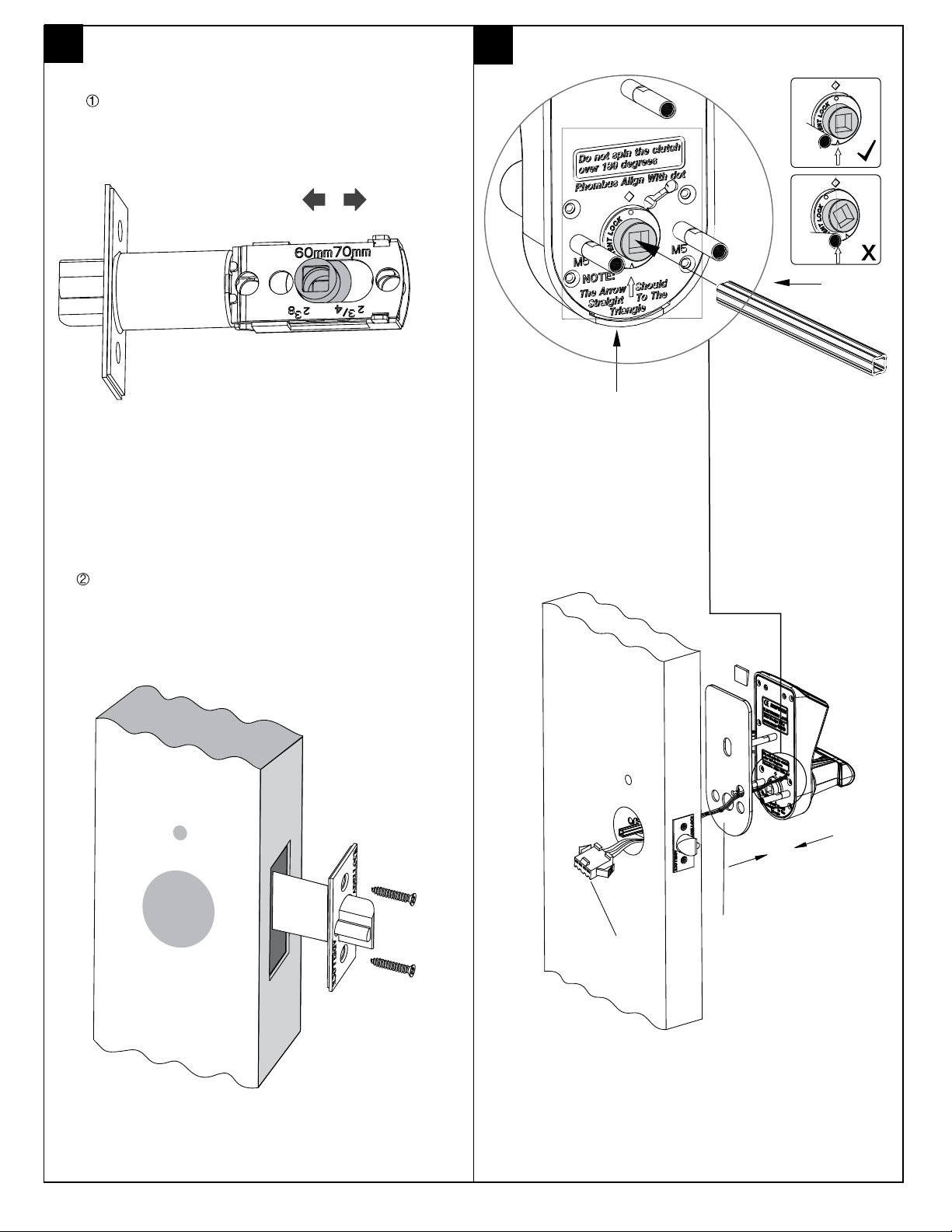
(70mmdiameter latch only) 70mmsィョlo pestillo de diィ「metro
70mm(backset)
2 3/4inch(backset)
Template
De cierre
Latch
Pestillo
this side up
este lado para arriba
12345678910 11
10mm
60mm
(Fixing screw hole)
Agujero del tornillo de fijaciィョn
Single latch optical fingerprint door Lock installation template
Puerta de huella dactilar ィョptica de pestillo ィイnico Plantilla de instalaciィョn de cierre
Match with the edge of the door
Hacer coincidir con el canto de la puerta
do not make the hole if it is existed
no hacer el agujero si ya hay uno
latch side plate
placa lateral del pestillo
Latch center line
Pestillo lィェnea central
(60mmdiameter latch only) 60mmsィョlo pestillo de diィ「metro
60mm(backset)
2 3/8inch(backset)
Template
De cierre
Latch
Pestillo
this side up
este lado para arriba
12345678910 11 12 13
10mm
60mm
(Fixing screw hole)
Agujero del tornillo de fijaciィョn
Single latch optical fingerprint door Lock installation template
Puerta de huella dactilar ィョptica de pestillo ィイnico Plantilla de instalaciィョn de cierre
Match with the edge of the door
Hacer coincidir con el canto de la puerta
do not make the hole if it is existed
no hacer el agujero si ya hay uno
latch side plate
placa lateral del pestillo
Latch center line
Pestillo lィェnea central
(70mmdiameter latch only) 70mmsィョlo pestillo de diィ「metro
70mm(backset)
2 3/4inch(backset)
Template
De cierre
Latch
Pestillo
this side up
este lado para arriba
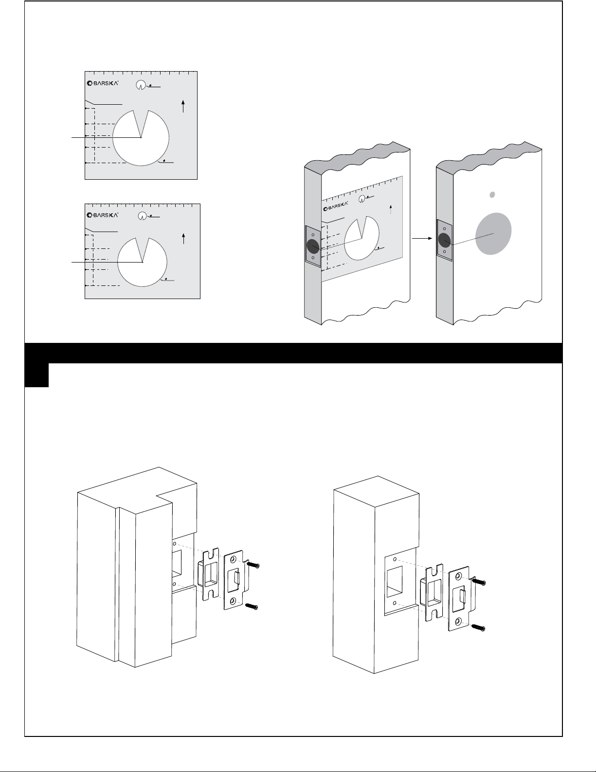
Paper template: the 2 3/8” [60mm] backset or 2 3/4” [70 mm] backset
Center point
Center point
2 3/8” [60mm] backset
2 3/4” [70 mm] backset
Note: Drill from both sides of the door to prevent unsightly damage.
1. Determine which template will fit your installation
( either the 2 3/8” [60mm] backset or 2 3/4” [70 mm] backset)
2. Place appropriate paper template (supplied) onto door and mark for holes.
Next drill the hole.
Door Preparation
Template for new door
2 3/8” [60mm]
2 3/4” [70 mm]
1. Mark location of strike on the door frame, making certain that the strike
opening is aligned with latch bolt.
Installing the strike plate
2
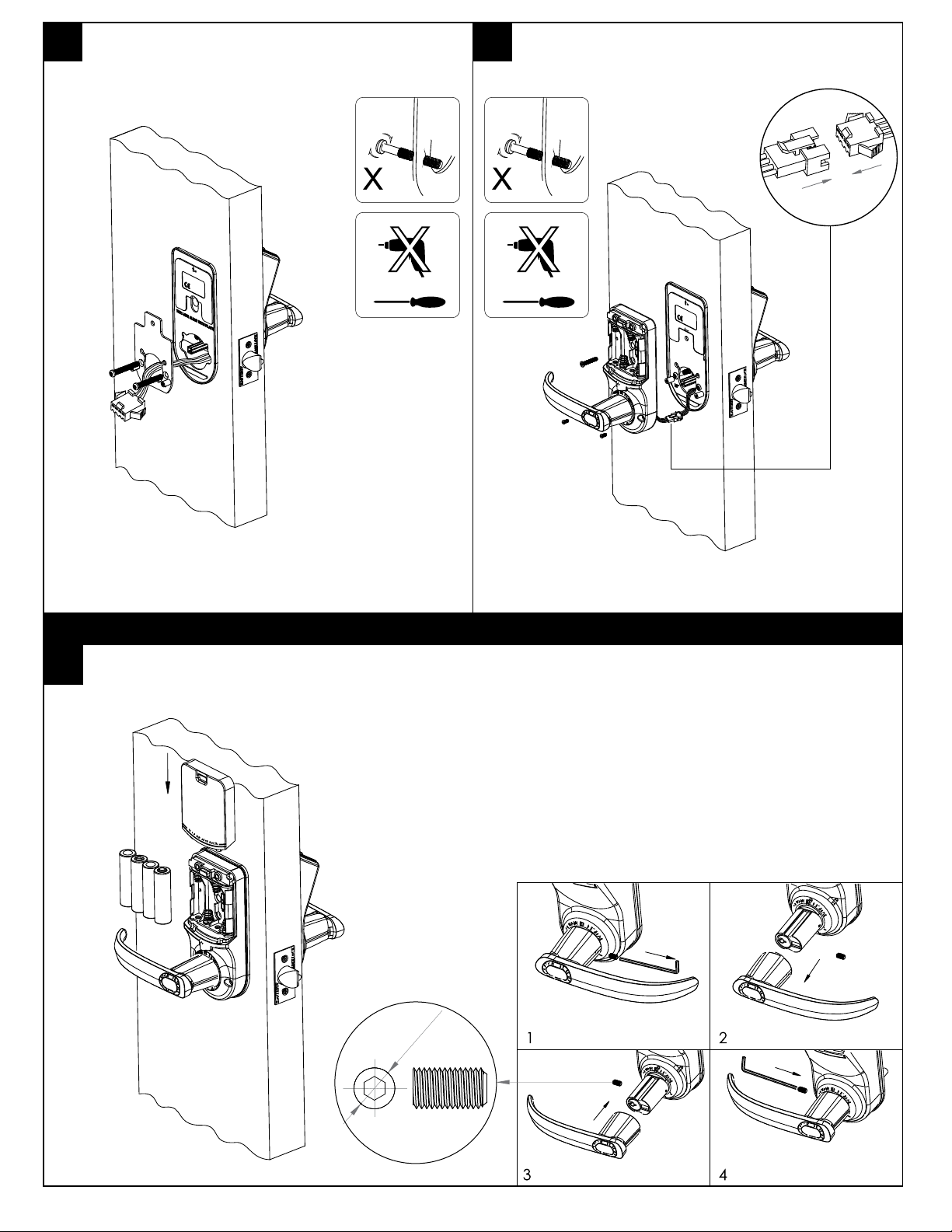
General door’s installation diagram
Type T-door’s installation diagram.