Mottura XDRIN 49XD1 Series User manual

49XD1...
49XD2...
GENERAL INSTRUCTIONS
This manual is intended for technically qualied and trained installers.
Mottura Serrature di Sicurezza S.p.A. thanks you for choosing this product and reminds you:
- To read these instructions very carefully before installing this product and before doing any maintenance.
- That all assembly and connection procedures must follow good practice procedures and comply with current laws and standards.
- To NOT install this product in explosive rooms or atmospheres or in the presence of inammable fumes/gases.
- To switch o the power supply and disconnect all live parts before doing any installation or maintenance work on the product. Take all possible
precautions to eliminate the risk of electrical shock when performing installation or maintenance procedures described in this manual.
- That the installer must deliver these instructions and all of the maintenance instructions to the user.
- To keep these instructions for future reference and attach the sales receipt to validate the warranty.
- To contact authorized dealers only in case of problems.
Mottura Serrature di Sicurezza S.p.A. may change the characteristics of the products described in these instructions at any time and without notice.
WARRANTY TERMS
This product has been inspected by Mottura Serrature di Sicurezza S.p.A. and is guaranteed to be free of all manufacturing defects for the time
specied by current Italian law, starting on the date of purchase indicated on the sales receipt. The warranty is in force if the sales receipt, showing
details identifying the product, is exhibited to customer service personnel. The warranty covers the replacement or repair of parts found defective
at origin due to manufacturing defects. Costs of shipping to and from service centres will be paid by the customer. In case of repeated malfunctions
of the same type or unrepairable defects, Mottura Serrature di Sicurezza S.p.A. may, at its own discretion, replace the entire product.
The warranty on the replaced product will continue until expiration of the original warranty. If service work must be performed at the customer’s
premises, the customer shall – if requested – pay the authorised technical personnel travel expenses.
Risks related to product transportation shall be covered by the customer when shipped directly by the customer, and by the authorised technician
when the product is picked up and shipped by the technician.
LIMITS OF LIABILITY
The warranty does not cover damage deriving from:
- negligence, carelessness or use in any manner not described in these instructions
- failure to protect the device before doing any procedure that may generate scrap or waste (welding, drilling of panels, drilling of structure, etc.)
that prevents its correct functioning
- maintenance performed in any manner not described in these instructions or by unauthorised personnel
- transport without the necessary precautions and from any circumstances that cannot be attributed to manufacturing defects.
In addition, Mottura Serrature di Sicurezza S.p.A. declines all liability for any damage to persons or property deriving from failure to observe all of
the precautions described herein.
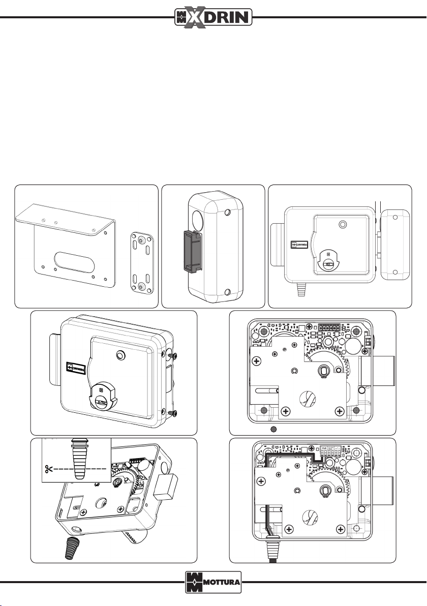
N.B.: All electrical connections and mounting operations as well as subsequent service operations must be performed with
the product DISCONNECTED from the power supply system.
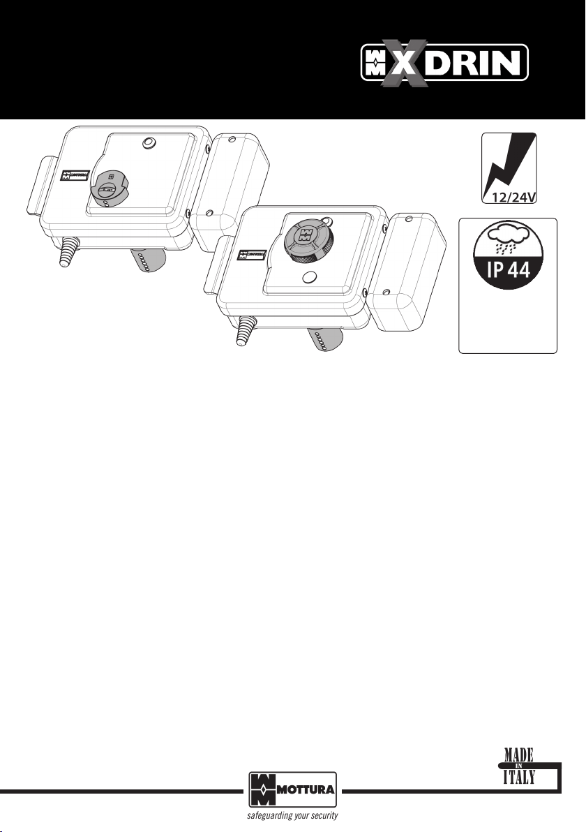
MOTORISED LOCK FOR EXTERIOR
DOORS OR GATES
49XD1… 49XD2…
USER MANUAL
Class 4 driving rain
resistance
Class 4 dust resistance

2
1 2
4 5
94415
94416
6 7
6-A
3
99342ENG - REV. 00
LOCK INSTALLATION
In case of a new installation use the supplied template.
Solder or fasten the optional plates (code 94415/94416 - Fig. 1) to the gate structure and temporarily position the lock
and strike plate. To position the strike plate correctly, use the supplied plastic template (Fig. 2), bearing in mind that
the distance between the lock and the strike plate must not exceed 10 mm (Fig. 3).
If replacing an existing electric lock, fasten the XDRIN lock using the existing plates/holes.
Mount the lock according to the following procedure:
- Unscrew the side screws and remove the cover (Fig. 4).
- Attach the lock and the strike plate using the supplied screws (Fig. 5).
- Cut the supplied graduated sleeved grommet (Fig. 6 - A) in order to have the right diameter for the entering power
supply cable, then insert the grommet into its designated hole at the bottom of the lock (Fig. 6).
- Insert the cable and pull it through to the terminal block attached to the electronic board by passing it under the gear
assembly plate (Fig. 7) and following the electrical connection diagrams shown in these instructions.
- Replace the cover and test the lock.
FASTENING HOLES
10 mm MAX

3
DESCRIPTION OF COMPONENTS
DESCRIPTION OF TERMINAL BLOCK PINS
Contact° No. Function
1Lock power supply
2Lock power supply
3Wet contact command 1
4Wet contact command 2
5Dry contact command (GND)
6Dry contact command
WIRING DIAGRAMS
N.B.: All connections must be performed by trained technicians in conformance with current electrical safety stan-
dards and following good practice procedures.
The lock must be powered with a 12V or 24V DC or AC current (Pin 1 and 2, no set polarity). Commands can be issued using 12V
or 24V DC or AC impulses through wet (powered) contacts (Pin 3 and 4) or dry (volt-free) contacts (Pin 5 and 6, no set polarity).
N.B.: XDRIN does not support voltages lower than 12V and greater than 24V. To power the lock, the use of Mottura
Network Adapter (code 99.683) is recommended. Otherwise, your power supply device must necessarily bear
the CE marking and conform to the technical specications listed in our catalogue.
XDRIN supports the simultaneous use of commands of dierent types (e.g., dry-contact and voltage impulse) in the
same lock. It is possible, for example, to install two buttons used, respectively, as dry contact and voltage impulse.
N.B.: Wires used for connecting the lock must be of a minimum section of 0.5mm2 and must be sheathed.
BUTTON A
LED
TERMINAL
REGULATING THE GRACE PERIOD
The grace period is the amount of time within which the door must be opened, measured from the moment the button
has been pressed. If the door has not been opened within the set grace period, it shall be locked automatically.
The default grace period is 10 seconds, but it may be changed from 5 to 60 seconds at 5-second increments. Grace
period modication procedure must be performed while the door is open and lock is unlocked, according to the
following procedure (see the components description chapter):
1. Remove the lock cover to access the internal electronic circuits;
2. Enter the programming mode by pressing the circuit button A for 3 seconds until the RED LED comes on, then release
the button;
3. The GREEN LED stays lit for 1 second and the counting starts;
4. The RED LED starts ashing. Each ash indicates a 5-second increment (e.g., 3 ashes = 15 seconds), up to a maximum
of 12 ashes (= 60 seconds);
5. Once the desired time has been reached, immediately press the button to conrm the new setting;
6. The RED-GREEN alternating ash conrms that programming has been completed successfully. Exiting the program-
ming mode is automatic.
N.B.: If the system does not detect that the button has been pressed by the user during the counting (12 ashes),
the procedure automatically restarts from step 3. If the button is not pressed again for another two cycles, the
system exits the programming mode automatically.
1 2 3 4 5 6
POWER
SUPPLY
12 - 24V
UNLOCK
IMPULSE
DRY
CONTACT

4
12 3 4 5 6
12 3 4 5 6
12 3 4 5 6
12 3 4 5 6
99342ENG - REV. 00
- Connection controlled by power transformer
The lock can be controlled via a wet connection coming from the lock transformer (12-24V AC). Pins 1 and 2 are used for
the device power supply (no set polarity); pin 4 is used for the button input;
- Connection controlled by power supply
The unlock command can be an electric impulse sent to the POSITIVE pole of the lock power supply.
- Connection with two separate power sources
In this case, the lock’s power source (12-24V AC/DC) can be dierent from the source of the unlocking command
impulse. There is no set polarity for the power supply (pins 1 and 2) and unlocking command impulse (pins 3 and 4).
Transformer or
Power supply
12 - 24 V (AC / DC)
Transformer or
Power supply
12 - 24 V (AC / DC)
Button
Lock
Power supply
12 - 24 V DC
Transformer
12 - 24 V AC
Button
Lock
Button
- Button connection using dry contact
In this conguration the lock is controlled using a dry (volt-free) contact. The button must therefore be connected to
pins 5 and 6 of the disconnectable terminal (no set polarity). The lock can be powered by 12 to 24V DC or AC current.
Transformer or
Power supply
12 - 24 V (AC / DC)
Button
Lock
N.B.: The lock must not be operated mechanically when activated electrically.
Third wire to be added
in case of replacement
with an electric lock
Third wire to be added
in case of replacement
with an electric lock
Lock

5
Lock
2-wire intercom
control unit (“BUS”)
Electro-lock pulse
Relay
Bus-based connection
N.B.: The relay used must have electrical specications that are compatible with the system in which it is installed.
- Bus-based connection to the control unit (two wires) via a voltage pulse relay
In this conguration the lock is controlled by a positive voltage pulse on Terminal 4.
The lock can be powered by a 12 to 24V current.
- Bus-based connection to the control unit (two wires) via a dry-contact relay
In this conguration the lock is controlled by a dry-contact (volt-free) relay.
The lock can be powered by a 12 to 24V current.
BUS-BASED CONNECTION
Lock
2-wire intercom control
unit (“BUS”)
Electro-lock pulse
Relay
Bus-based connection
To ensure correct operation and alignment between sensor and magnet of the XDRIN lock during closing, the door /
gate should be equipped with a door-closing device.
CLOSEDOOR DEVICE

6
1 2 3 4 5 6
99.729 99.730
99.686 99.736
99.748 99.749
99.739 99.689
99.735
99.734
99.724
95148/25 95248/25
99342ENG - REV. 00
Dry
contact
only
Class 5 dust resistance
Class 4 protection
against water jets from
all directions.
Lock
CABLE
99.699
Example of lock assembly using external escutcheons
JAMMING ERRORS
In the event of jamming due to mechanical problems that prevent proper bolting, the lock will automatically proceed
to make 5 additional locking attempts. If none of the attempts has been successful and the lock remains unlocked, the
jamming error shall be signalled with then continuous ashing of the red LED, which will terminate only after the user
has activated the lock electrical control.
Logical
unlocking unit
Bluetooth
device / receiver

7
23
45
1
6
REPLACING AN EXTERNAL CYLINDER
To replace the cylinder, use the supplied screws.
- Unscrew the side screws and remove the cover (Fig. 1).
- Remove the entire gear assembly (plate, 2 toothed wheels, motor) kept in place by 3 screws (Fig. 2) and disconnect
the motor connector.
- Lift the highlighted lever (Fig. 3) and move the bolt to create the space necessary for unscrewing the screws that keep
the cylinder in place (Fig. 4).
- Remove the existing cylinder.
- On the new cylinder, shorten the stem if necessary (5 mm projection from the cylinder brass spacer - Fig. 5).
- Remount the cylinder (Fig. 6).
- Reconnect the motor connector, reinsert the gear assembly, making sure that the toothed wheels are aligned correctly
with the deadbolt teeth and verifying they t by moving the assembly manually.
- Replace the cover.
This lock oers the possibility of replacing the internal and/or external cylinder with cylinders of the same type (e.g., of
the same master system). If the gate thickness is greater than the cylinder length, you can use the special extension KIT
(optional) code 98C47ES001.
CHANGING THE KEY ENTRY
- Unscrew the side screws and remove the cover (Fig. 1).
- Remove the entire gear assembly (plate, 2 toothed wheels, motor) kept in place by 3 screws (Fig. 2) and disconnect
the motor connector.
- Lift the highlighted lever (Fig. 3) and move the bolt to create the space necessary for unscrewing the screws that keep
the cylinder in place (Fig. 4).
- Loosen the screws that keep the cylinder in place, remove the 2 screws set on the box (Fig. 7) and move the plate to the
desired key entry position – 50, 60 or 70 (Fig. 8), replace the 2 box screws and tighten the 2 cylinder screws.
- Insert the pin into the deadbolt (as shown in Fig. 9) according to the selected key entry position.
- Reconnect the motor connector, reinsert the gear assembly, making sure that the toothed wheels are aligned correctly
with the deadbolt teeth and verifying they t by moving the assembly manually.
- Replace the cover.

8
12 3
79
8
99342ENG - REV. 00
Power supply From 12 to 24V AC/DC
Versions Right-hand or left-hand knob/cylinder
Right-hand or left-hand cylinder/cylinder
Entry Adjustable 50 - 60 - 70 mm
Max. power absorption
(during motor stall) 500mA
Holding current 30mA
Operating temperature From -25°C to 80°C
Automatic relocking grace
period
Adjustable from 5 to 60 seconds with
5-second increments
Door bolted signal Red/green dual colour LED
Protection rating IP44
DRAWINGS AND TECHNICAL SPECIFICATIONS
External cylinder extension
kit cod. 98C47ES001
REPLACING AN INTERNAL CYLINDER
Unscrew the side screws and remove the cover (Fig. 1).
Remove the tailpiece by unscrewing the two highlighted screws (Fig. 2), remove the existing cylinder by unscrewing
the 2 screws (Fig. 3).
Install the new cylinder, then reassemble the tailpiece and replace the cover.
Right-hand version
From 50 to 105 mm
Mottura-made
cylinders
Other cylinder
types

www.mottura.it
99342ENG - REV. 00 - 07/18 - a_020258
Internal cylinder version
49XD1...
Internal knob version
49XD2...
This manual suits for next models
1
Table of contents
Other Mottura Door Lock manuals
Popular Door Lock manuals by other brands

SDC
SDC Z7600 Series installation instructions

Schlage
Schlage P515-302 installation instructions

Assa Abloy
Assa Abloy Yale 6100 installation instructions

Kwikset
Kwikset 699 FN manual

Assa Abloy
Assa Abloy RIXSON W0700 Series installation instructions

Assa Abloy
Assa Abloy ADAMS RITE 4300 Series installation instructions