Contents
I - 1
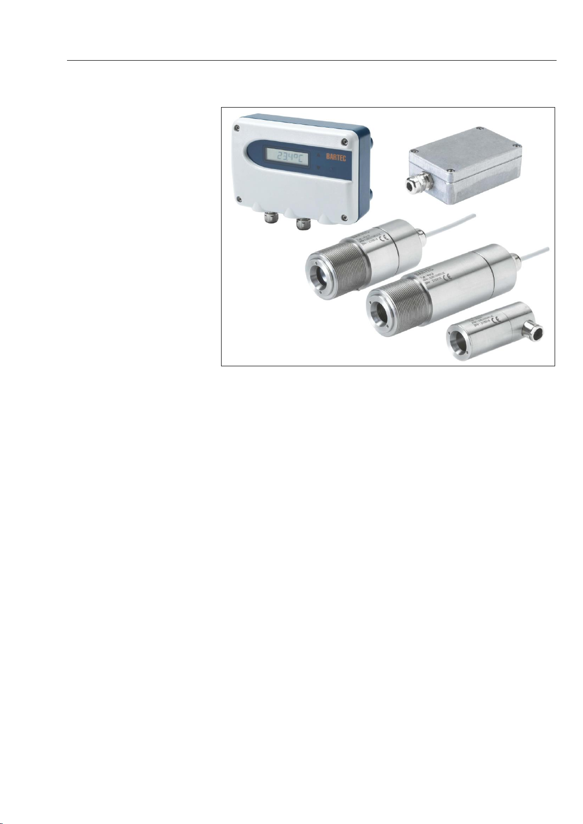
Operating Instructions Radiation sensors R3XX
Table of Contents
1System description .........................................................................................................................1
1.1 Properties and fields of use....................................................................................................1
1.2 Sensor versions......................................................................................................................2
1.3 Scope of delivery....................................................................................................................3
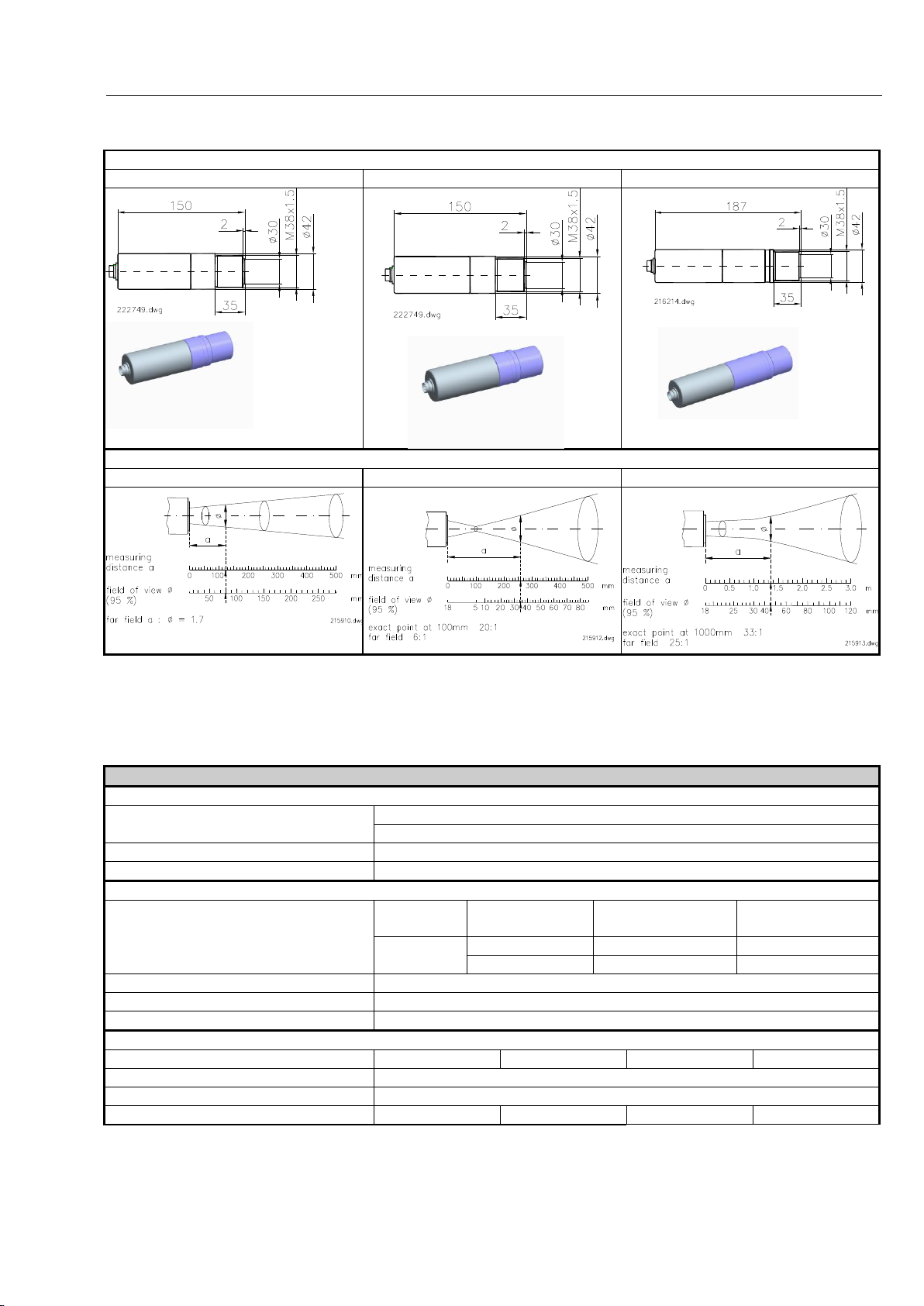
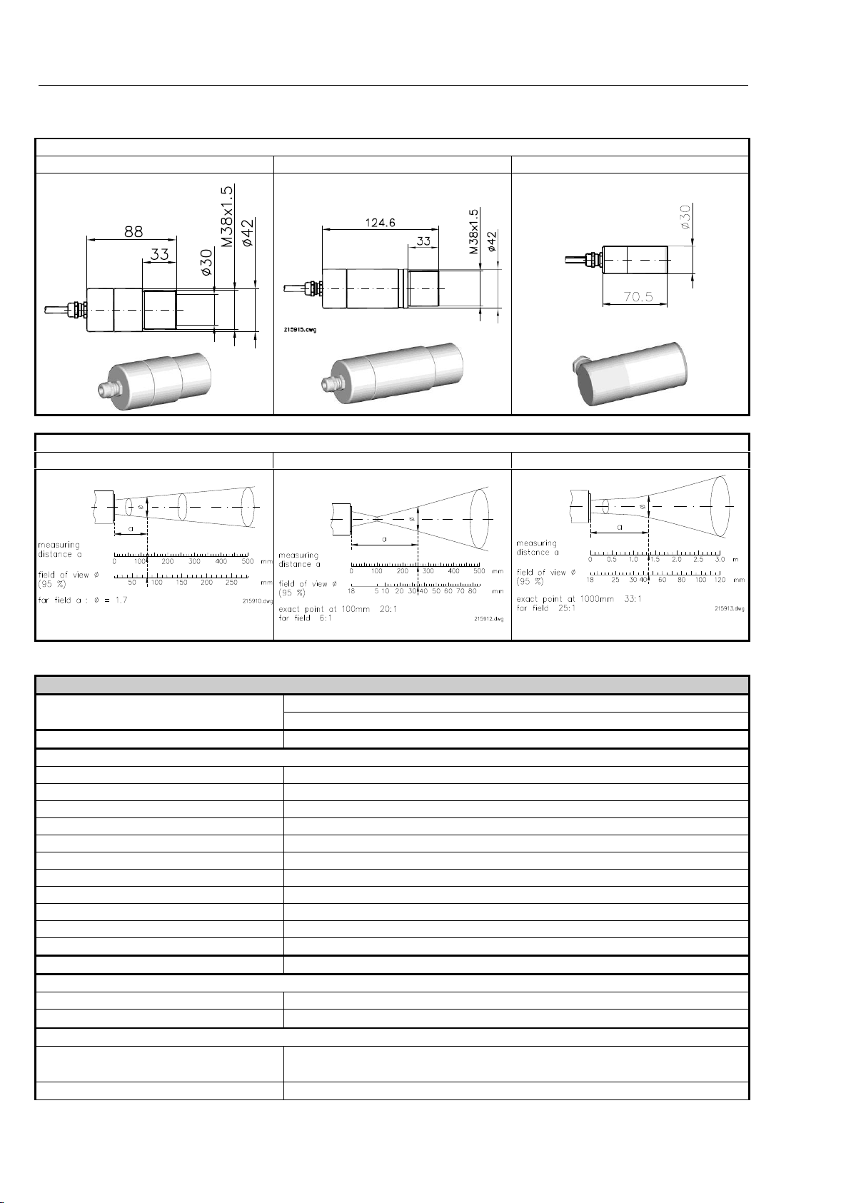
1.4 Technical data ........................................................................................................................4
1.4.1 Thermophil®INFRAsmart ....................................................................................................4
1.4.2 Thermophil®INFRAht ..........................................................................................................5
2Safety precautions ..........................................................................................................................9
2.1 General information................................................................................................................9
2.2 Installation location.................................................................................................................9
2.3 Electrical connection.............................................................................................................10
2.4 Operating the equipment......................................................................................................10
3Installation......................................................................................................................................12
3.1 Installation location...............................................................................................................12
3.2 Measurement distance.........................................................................................................13
3.3 Aids, accessories..................................................................................................................14
3.3.1 Safety instructions for the operation of Laserpointer type R300-101................................26
3.3.2 Safety instructions for the utilisation of the IR protection window Zn-Se ..........................26
type R300-136 (order no. 301954)
3.4 Connection ...........................................................................................................................27
3.4.1 R 300, R 301, R 302 ..........................................................................................................27
3.4.1.1 Connection via plug........................................................................................................27
3.4.2 R 310, R311, R312, R320 .................................................................................................28
4Operation........................................................................................................................................31
4.1 Measurement operation........................................................................................................31
4.2 Configuration ........................................................................................................................31
4.2.1 Configuration with transmitter TR 41-10............................................................................32
4.2.1.1 Configuration process ....................................................................................................32
4.2.1.2 Parameters.....................................................................................................................33
4.2.1.3 Default values.................................................................................................................37
4.2.1.4 Configuration of the sensor data (not implemented).....................................................38
4.2.1.5 Test mode.......................................................................................................................41
4.2.2 Configuration with the HART®modem, Type R 300-107 ..................................................42
4.2.2.1 Connecting the HART®modem......................................................................................42
4.2.2.2 Software .........................................................................................................................43
5Configuration PACTware..............................................................................................................45
6Maintenance...................................................................................................................................57
7HART®protocol .............................................................................................................................61
8Additional instructions for use in dust-explosive areas...........................................................65