EXaminer®CUI 310 E NB
Reservation Technical data subject to change without notice. No claims for damages arising from alterations, errors or misprints shall be allowed.
3
ATEX/IECEx certification
Reference Standard
EXaminer®CUI 310 E NB sensor is designed in accordance with
the following standards.
Standards Document
Number Title
EN IEC 60079-0:2018
IEC 60079-0:2017
Explosive atmospheres, Part 0:
Equipment General requirements
EN 60079-11:2012
IEC 60079-11:2011
Explosive atmospheres, Part 11:
Equipment protection by intrinsic safety “i”
ATEX/IECEx Approval
IECEx DNV 21.0037X Ex ia IIC T4 Ga
-40 °C ≤ Ta ≤ +80 °C
DNV 21 ATEX 73941X II 1G Ex ia T4 IIC Ga
Tamb -40 °C to +80 °C
DNV GL Presafe AS
2460 Veritasveien 3
N-1363 Høvik
Norway
Label
Installation and Startup
Installation of the EXaminer®CUI 310 E NB
The EXaminer®CUI 310 E NB sensor is designed for mounting on
the cladding on pipes for measurement of temperature, relative
humidity and if water is present. The included drill bit has a Torx
T30 head.
Mounting the sensor on components with normal operating
surface temperature of 80 °C or higher or below -40 °C must be
avoided.
Operating in temperatures outside normal operating
temperatures (5 °C to 40 °C) may have significant impact on
battery lifetime.
Specific conditions for EXaminer®CUI 310 E NB
“X”- Equipment must be mounted on the metallic enclosure and/
or contact with earth must be assured.
The sensor is marked:
WARNING
POTENTIAL ELECTROSTATIC CHARGING HAZARD –
SEE INSTRUCTION
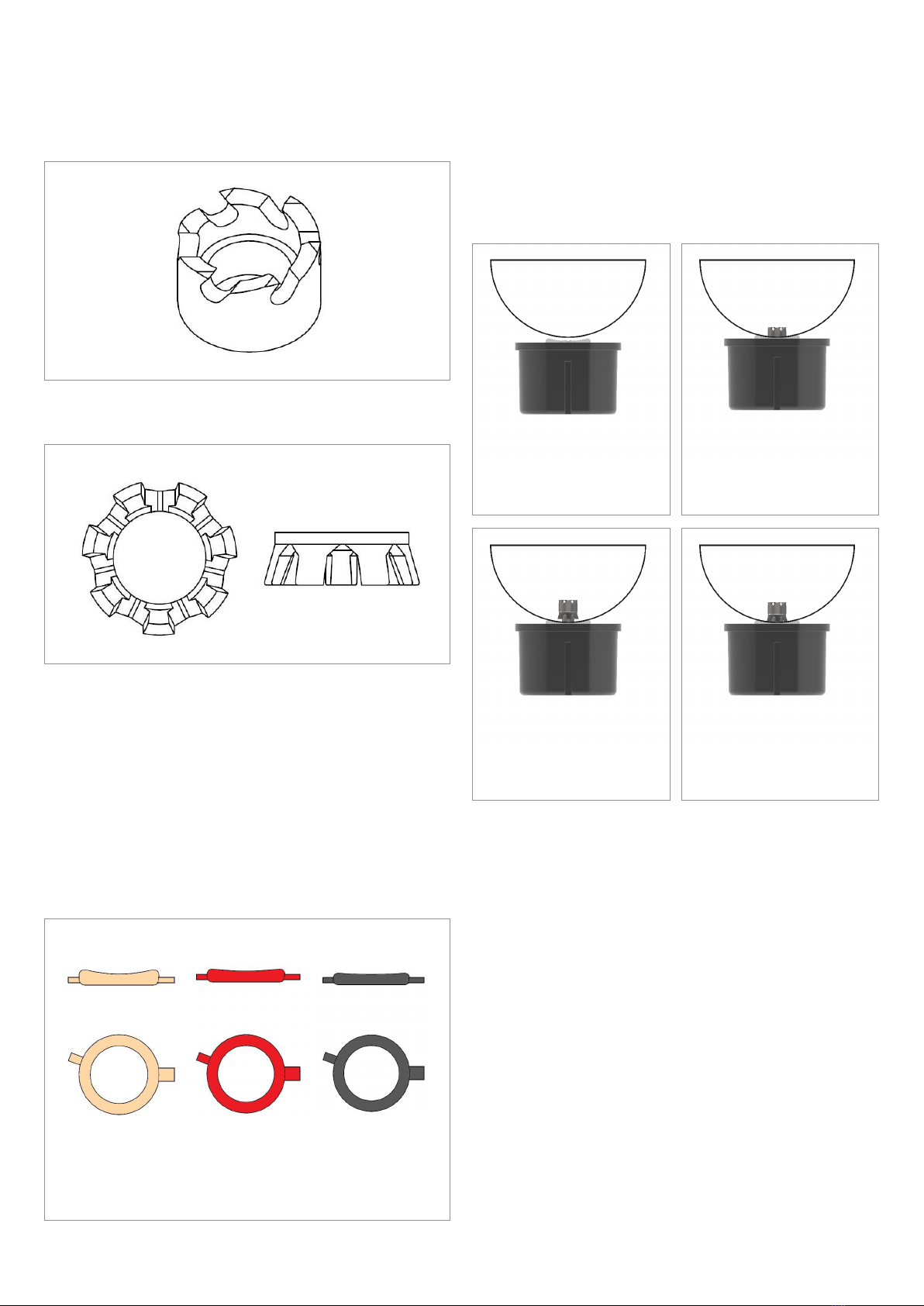
Mounting principle
NOTE
Before mounting the sensor ensure that the place selected is
not near a cladding joint or other obstructions/irregularities
preventing the sensor to rest securely on the cladding.
Preferably, the centre of the hole in the cladding should be no
closer than 40 mm from such irregularity.
Installation by using a designated jig
The sensor is fitted with an integrated drill bit allowing installa-
tion by a special designed installation jig. Once installed correctly
in the jig and positioned on the cladding, the jig will apply correct
pressure and rotational speed to the sensor drill bit.
Manual installation
Alternatively 12 or 14mm holes can be pre-drilled in the cladding
and then by positioning the sensor drill bit center/center in the
hole, use a screwdriver or similar to press the drill bit assembly
though the hole all the way in until the Umbrella Sensor Lock is
engaged on the inside of the cladding.
NOTE
• Please ensure that the sensor is properly attached and seals
off the hole.
• The Flat sides on the sensor housing must be positioned as
shown on figure 3.
Robotic installation
The mountable sensor is also configured to allow installation by a
robot as it only requires a single driving force to mount the sensor
at a desired location.The robot is being developed separately.
EXaminer CUI®310 E NB
17-2131-****/****
EX II 1G Ex ia IIC T4 Ga -40 °C ≤ Ta ≤ +80 °C
IECEx DNV 21.0037X
ATEX DNV 21 ATEX 73941X
WARNING - POTENTIAL ELECTROSTATIC
CHARGING HAZARD - SEE INSTRUCTION
0044
IP 67
Batch No. YYWW
XX:XX:XX:XX:XX:XX
Data
Matrix
Code
97980
Bad Mergentheim
Germany