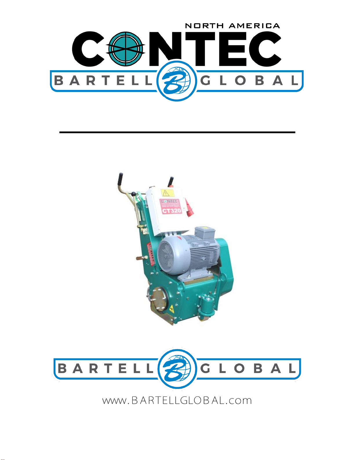
OPERATING SAFETY PRECAUTIONS
The CT320 Floor Planers are constructed according to existing safety rules and
regulations. These technical precautions should not be removed or changed under any
circumstances. While operating the machines the following points should also be kept in mind:
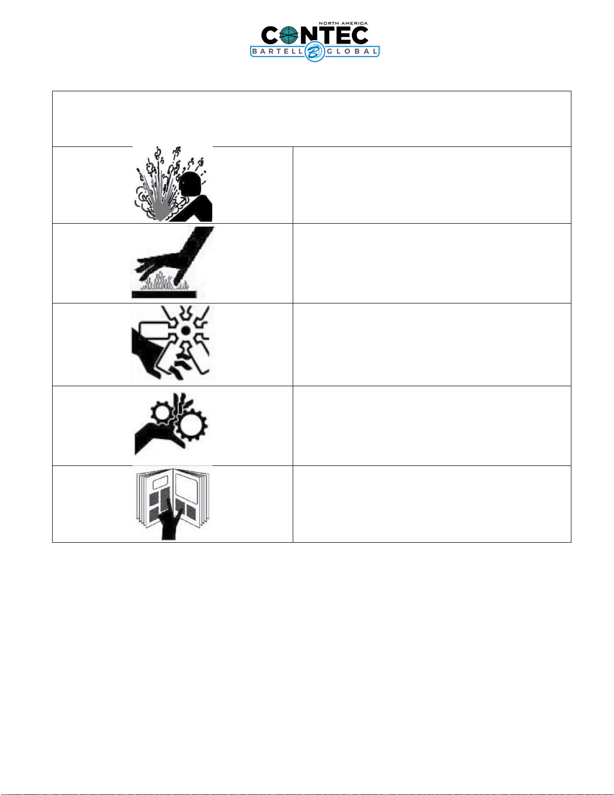
The instructions provided in this manual are done so to ensure the operator’s safety as well
as that of others, the equipment, and the job site. Failure to follow these guidelines can lead to
serious personal injury and even death. The operator and any service personnel should read
and understand the entire manual before working with or servicing any Contec Floor Planer.
•The Planers should always be operated with all safety covers and technical precautions.
•During transport, cleaning, repair or maintenance the Planer must be disconnected from
the power supply. That also applies to the changing of tools.
•The operator should never leave the machine unattended during operation.
•Before leaving the machine, all rotary parts should be brought to a standstill. Electric
models must be disconnected from the power supply. Make sure that the machine
cannot roll or move by itself.
•After any maintenance and adjustment all safety covers must be reattached.
•Ear protectors must be worn.
•Eye protectors must be worn.
•Safety shoes with steel caps must be worn.
•In the event of a large amount of dust during operation, connect a dust collector to the
Planer.
•Depending on the floor (floor coating) planeing can produce gases. The operator must
be held responsible if these generated gases are dangerous and if protection is
necessary. planeing floors containing asbestos is especially dangerous and can cause
health problems. Special masks must be worn which keep the breathing air clean. A dust
collector must be used and should be equipped with filters suitable for asbestos dust.
•The floor must be brushed before grinding because loose material could get into the
tools and fly away. Anchor screws and bolts coming out of the floor can also be seen
better if the floor is clean. If the grinding head hits an anchor screw or bolt, then serious
damage can be caused to the machine or planeing drum.
IMPORTANT: NEVER attempt to disable or circumvent these safety devices. They are
present for the operator’s protection and any tampering will result in substantial risk to
the operator and all present at the job site. If your planer’s safety devices have been
tampered with, do not use the equipment. Immediately contact your sales representative
to obtain replacement parts or return the planer to your dealer for repairs.