Bartels Mikrotechnik microComponents mp6-XEVA User manual
1
Rev. 1.0 (04.2020)
Operating Manual for
mp6-XEVA Board

2
Rev. 1.0 (04.2020)
Content
Operating Manual for mp6-XEVA Board ...............................................................................................................................................1
General............................................................................................................................................................................................................3
Declaration of conformity.....................................................................................................................................................................3
Description of functions........................................................................................................................................................................3
Proper use.......................................................................................................................................................................................................4
Intended purpose.....................................................................................................................................................................................4
Misuse.........................................................................................................................................................................................................4
Staff selection and qualification. .......................................................................................................................................................4
About this operating manual...............................................................................................................................................................4
The mp6-XEVA evaluation board.............................................................................................................................................................4
Safety notice.............................................................................................................................................................................................5
Electrical specifications mp6-XEVA evaluation board..................................................................................................................5
Functional elements. ..............................................................................................................................................................................5
Operation...................................................................................................................................................................................................6
Pump frequency setting with jumper JP1. .......................................................................................................................................6
Pump amplitude setting with jumper JP2........................................................................................................................................7
Operation voltage setting with jumper JP3.....................................................................................................................................7
Connecting the pump via CON2. ........................................................................................................................................................7

3
Rev. 1.0 (04.2020)
General
This operating manual contains all necessary instructions for the installation, commissioning, operation and
maintenance of the evaluation board mp6-XEVA. The manual is intended to help you achieving optimal results in a
short time and shall assist avoiding possible sources of errors. The operating manual of the micropumps and other
controllers are available separately.
The products have been designed with state-of-the-art technology and in accordance with all relevant safety
regulations. However, a risk of damage to the units, other property, the operator and/or other persons cannot be
fully excluded.
Always ensure that specialized and trained personnel will comply with the following general instructions.
Therefore, please keep this manual and hand out copies as required.
Bartels Mikrotechnik GmbH rejects any responsibility for damages to persons or property resulting from non-
compliance with the instructions in this manual. In this case all warranties shall be void.
Declaration of conformity.
Bartels Mikrotechnik GmbH declares that the products are compliant to the RoHS directive 2011/65/EU. The
controllers comply with the requirements of EMV 2014/30/EU and CE markings have been affixed to the devices.
Additionally, the controllers are also compliant to the EU Low Voltage Directive 2014/35/EU.
Description of functions.
The micropumps have been developed for the transport of gases or liquids. The controllers have been developed for
operating the micropumps. Bartels Mikrotechnik can assume no liability for damages resulting from the pump
media. This applies especially for hazardous fluids.
The pumps must be operated with Bartels Mikrotechnik electronics. Bartels Mikrotechnik GmbH cannot guarantee
the proper work of the units with customer specific electronics. If other controllers than the ones from Bartels
Mikrotechnik are used, Bartels Mikrotechnik disclaims any warranty.
Moreover, please note that components of the controller and pump are operating with high-voltage. Therefore,
persons wearing pacemakers are recommended to avoid the operating system.
Bartels Mikrotechnik assumes no liability for abnormal handling, improper or negligent use of the micropump and
the controller that is not conform to the specified purpose of the system. This applies especially for micropump
controllers, components and systems of other manufacturers, which have not been certified by Bartels
Mikrotechnik.
We guarantee that the micropumps comply with the actual state of scientific and technical knowledge and due to
this, the operational risks are limited to a minimum.
Do not open the housing of the micropump and the controllers. In those cases, Bartels Mikrotechnik cannot issue a
guaranty anymore. Please keep this manual safe and give a copy to all users.
4
Rev. 1.0 (04.2020)
Proper use
Intended purpose.
The micropump is intended for pumping liquids or gases with varying flow rates controlled by the electronics. The
controllers are intended for operating the micropumps. Any other use of the micropump or controller unit is
deemed improper.
Do not make any modifications or extensions to the pump or controller without the prior written consent of the
manufacturer. Such modifications may impair the safety of the unit and are prohibited! Bartels Mikrotechnik GmbH
rejects any responsibility for damage to the unit caused by unauthorized modifications to the pump and risk and
liability are automatically transferred to the operator.
Misuse.
The use of liquids, which may alone or in combination create explosive or otherwise health-endangering conditions
(including vapors) is not permitted.
Staff selection and qualification.
All work in connection with the installation, assembly, commissioning/decommissioning, disassembly, operation,
servicing, cleaning and repairing of the pump and the controller must be carried out by qualified, suitably trained
and instructed personnel. Work on electrical components and assemblies must be carried out by personnel with the
necessary qualifications and skills.
About this operating manual.
Warnings and important notes are clearly identified as such in the text. The relevant text sections feature a specific
sign. However, this icon cannot replace the safety instructions. Therefore, carefully read all safety instructions in
this manual. Warnings and important notes in this text are highlighted as shown below, according to the severity
of the damage that might result from non-compliance.
DANGER
DANGER indicates a hazard with a high level of RISK THAT, if not avoided, will result in death or serious injury.
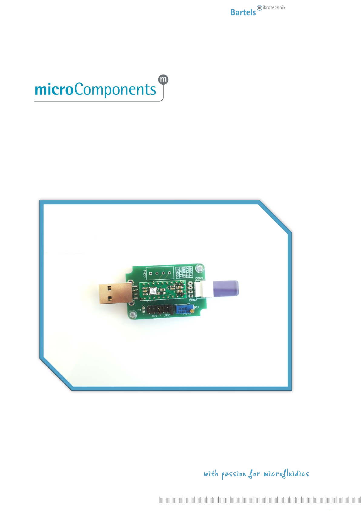
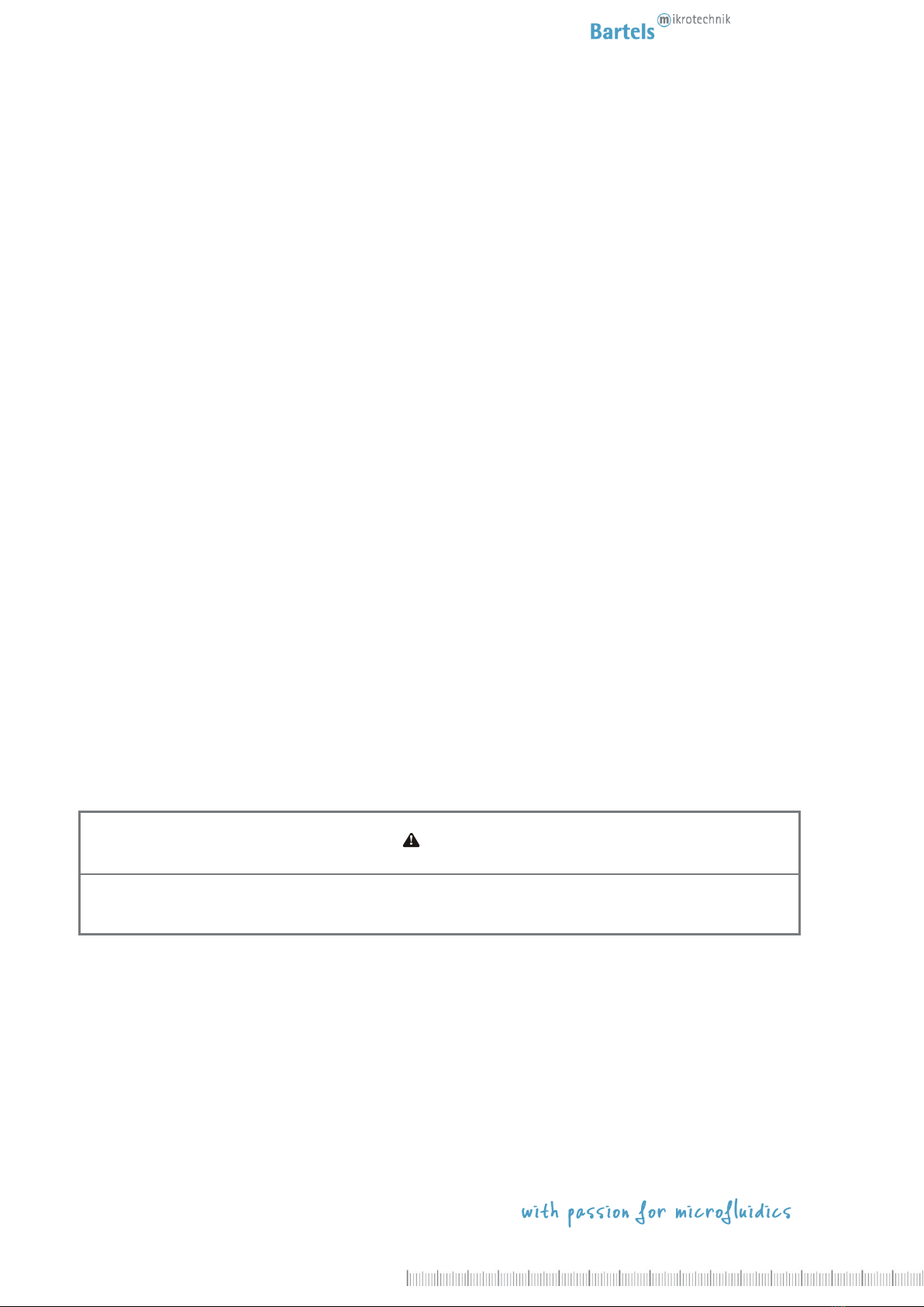
The mp6-XEVA evaluation board
The evaluation board enables the simple use of one micropump of the mp6-series based on the mp6-XOEM
controller. Next to present standard parameter (250 Vpp, 200 Hz) the mp6-XEVA also allows to adjust the pump
parameters, partly by external tuning. As the supply voltage of the module can be provided via USB (no data
interface), just attach it to a USB power supply and start the evaluation. Alternatively, it can also be supplied by a
2.5 –5 V power supply.
5
Rev. 1.0 (04.2020)
Safety notice.
The mp6-XEVA generates voltages of up to 250 Vpp. All parts of the mp6-XEVA evaluation board can carry voltages
in this range. Therefore, the board should only be used by qualified personnel. Although the output power of the
module is very low, proper insulation according to the application conditions needs to be considered by the
customer. This especially applies to the lower side of the PCB. Contact with water or other liquids needs to be
prevented. The pump must not be changed while the board is powered.
DANGER
The EVALUATION BOARD can carry high voltage!
Be careful, WHILE CONNECTING AND HANDLING THE BOARD!
Electrical specifications mp6-XEVA evaluation board.
As the evaluation board is based on the mp6-XOEM module, all electrical characteristics and specifications of this
product must be considered. Please have a look at the corresponding manual for more details.
Functional elements.
1Elements are listed with their names according to the printed description on the PCB.
Connectors:
CON 1 –Screw terminal for external power supply, external clock, amplitude signal, I²C-interface
CON 2 –Solder terminal for extension cable to connect one micropump of the mp6-series
CON 3 –Molex connector to connect one micropump of the mp6-series
Mini USB connector for voltage supply via USB power supply, powerbank or computer
6
Rev. 1.0 (04.2020)
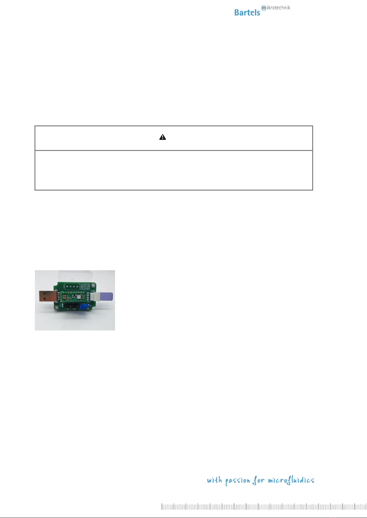
Jumpers:
JP1 –Jumper for pump frequency setting
JP2 –Jumper for pump amplitude setting
JP3 –Jumper for power supply setting
Others:
POT1 –Variable resistor for amplitude adjustment
C1 –is not used with mp6-XOEM
Operation.
To operate a pump with the evaluation board, the following steps are necessary:
Step 1: Connect the micropump of the mp6-series to the board. Due to the orientation of the connector, the
pump needs to be inserted with its metallic contacts upwards.
Step 2: Choose the pump frequency setting with Jumper 1
Step 3: Choose the pump amplitude setting with Jumper 2
Step 4: Choose the power supply setting with Jumper 3 (CON 1- or USB-port).
Step 5: Connect the board to the power supply
Pump frequency setting with jumper JP1.
Frequency defined by
clock signal at Pin 3 (CLK)
of screw terminal CON1
This setting has no
functionality with mp6-XOEM
Internal frequency of the mp6-XOEM
(200 Hz)
More information on the frequency setting with the CLK signal can be found in the mp6-XOEM manual.

7
Rev. 1.0 (04.2020)
Pump amplitude setting with jumper JP2.
Amplitude defined by
AMPLITUDE signal at
Pin 4 (AMP)
of screw terminal CON1
Amplitude defined by
position of potentiometer
POT1
Maximal amplitude
(250 Vpp)
More information on the amplitude setting with the AMP signal can be found in the mp6-XOEM manual.
Operation voltage setting with jumper JP3.
Power supply via
Pin 1 (Vcc) and Pin 2 (GND)
of screw terminal CON1
Power supply via Mini-USB-port
Connecting the pump via CON2.
If the micropump of the mp6-series shall not be connected directly to the PCB with the Molex connector CON 3, an
extension cable can be soldered directly to the connector CON 2 or a fitting Wire-To-Board connector like Molex
PicoBlade Series 53047 can be used to attach an extension cable between the micropump and board.
The solder pads have the following pin assignments (from top to bottom):
P2 - (negative lead of Piezo 2)
P2 + (positive lead of Piezo 2)
P1 + (positive lead of Piezo 1)
P1 - (negative lead of Piezo 1)
Please make sure that the cable can handle voltages up to 250 Vpp and ensure proper insulation of the cable!

8
Rev. 1.0 (04.2020)
Using the I²C-interface of the mp6-XOEM.
The mp6-XOEM can be controlled via I²C when the onboard microcontroller is disabled. To do this, the reset pin of
the mp6-XOEM has to be tied to GND. The trace between pins 15 and 16 of the IC-socket has to be removed on the
bottom side of the board and a zero Ohm resistor (or solder joint) has to be attached to the pads next to the pins,
so the reset pin (pin 15) is directly connected to the GND plane. Referre to the mp6-XOEM manual for information
about the I²C-interface. The protocol is identical to the mp6-QuadOEM. The screw terminals 5 and 6 can be used to
connect the interface wires. Please note that the address pins A0 and A1 are directly tied to GND on the mp6-XEVA
so the slave address is fixed.
2Bottom side of mp6-XEVA board.
All values are approximate and no guarantee of specific technical properties.
Changes in the course of technical progress are possible without notice.

9
Rev. 1.0 (04.2020)
Contact Data:
Bartels Mikrotechnik GmbH
Konrad-Adenauer-Allee 11
44263 Dortmund Germany
http://www.bartels-mikrotechnik.de
info@bartels-mikrotechnik.de
Tel: +49-231-47730-500
Fax: +49-231-47730-501
Visit our Website
http://www.bartels-mikrotechnik.de
for further information on applications.
Tutorials and helpful answers to frequently asked
questions can be found in our FAQ
http://blog.bartels-mikrotechnik.de
or on our YouTube channel
https://www.youtube.com/user/BartelsMikrotechnik
Social Media: Facebook, Twitter, Instagram, LinkedIn
Table of contents
Other Bartels Mikrotechnik Motherboard manuals


