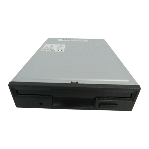
Sony MP-F17W User manual

,-'
I
,:,:
~
-
~,~
fCR
0
FLO
PP
'(
DJ
SX
OR.l
'I
E
Rev.A
70112
SONY
·SERVICE
MANUAL

TABLE
OF
CONTENTS
Des cr
ip
ti
on
SECT!
ON
1
SECTION
2 I
tHROOUCT!
ON
TOOL
SAND
MEASUR
I
NG
I
NST.RUME
NTS
.......................
.
~
1
2
2
3
Z-l
GENERAL
AND
SPECIAL
TOOL
LIST
Z-Z
SPECIAL
TOOLS
Z-
3
SECT!
ON
3
SYSTEM
CONFIGURATIONS
TROUBLESHOOTI
NG
••••••••••••••••••••••••••••••••••••••••
15
18
3
-1
BEFORE
TROUBLESHOOTING
••••••••••••••••..••••••••••••••
18
3-Z
TYPES
OF
ERROR
ON
A
SYSTEM
LEVEL
3-3
FAULT
DIAGNOSIS
BY
MFD
FUNCfIOO
amCKER
II
3-4
FINAL
CHECK
........
...................................
3-4-1
Final
Check
for
1MBy
t e
Mode
.......................
3-4-Z
Final
Check
for
2MBy
t e
Mode
.......................
3-4-3
Error
Message
18
18
26
26
30
SECTION
4
PART
RE
PLACEMENT
•••••••••••••••••••••••••••••••••••••••
35
4-1
COVER
ASS'Y
REPLACEMENT
•••••••••••••••.••••••••••.••••
35
4-Z
FRONT
PANEL
ASS'Y
AND
EIECf
BUTTON
REPLACEMENT
••••••••
35
4-3
LG-Z
MOUNTED
BOARD
REPLACEMENT
•••••••••••••••••.••••••
35
4- 4
MT-
Z
MOUNTED
BOARD
REPLACEMENT
36
4-5
HALL
IC
ASS'Y
REPLACEMENT
••••••••••••.••••••••.••••••••
36
4-6
CASSETTE
HOLDER
ASS'Y
REPLACEMENT
•.•..••.
4-7
SLIDE
PLATE
ASS'Y
REPLACEMENT
••••••••••••
37
37
4-
8
00
SENSOR
REPLACEMENT
••••••••••.•••••••.••••••••••.•••
38
4-9
HEAD
CARRIAGE
ASS'Y
REPLACEMENT
•••••••••••••••••••.•••
38
4-10
STEPPING
MO~R
ASS'Y
(RO~R
ASS'Y
AND
STATOR
ASS'Y)
REP
LACBMENT
••••••••••••••••••••••••••••••••••••••••••
39
4-11
OIL
DAMPER
REPLACEMENT
•••••••••••••••••••••••••••••••
39
4-12
COMBINATION
OF
HEAD
CARRIAGE
ASS'Y
AND
LG-Z
MOUNTED
BOARD
••••••••••••••••••••••••••••••••••••••••••••••••
40
SECT!
ON
5
CHECK
AND
ADJUSTMENT
•••••••••••••••••••••••••••••••••••
41
5-1
RADIAL
ALIGNMENT
AND
TRKOO
SENSOR
5-2
HEAD
CCMPLIANCE
5-
3
INDEX
PHASE
...........................................
5-
4
.HEAD
CLEANING
•••••••••••••••••••••••••••••••••••••••••
47
SECTlON·6
PARTS
LOCATION
AND
LIST
(For
MP-F17W-50L)
..............
49
SECTI
ON
6-1
PARTS
ASS'Y
LOCATION
6-2
MECHANICAL
PARTS
LIST
6-3
OVER
ALL
DIAGRAM
6-4
CIRCUIT
DIAGRAM
••••
6-'
PARTS
LAYCJt.rr
.•...•••.••.•....•.•••••••.•••.••.••••••••
6-
6 BLEC'fRIC PARTS
••••••••••••••••••••••••••••••••••••••••
7
PARTS
LOCATION
AND
LIST
(For
MP-FI1W-50D)
••••••••••••••
7-1
PARTS
ASS'Y
LOCATION
7-2
MECHANICAL
PARTS
LIST
,
49
51
52
53
56
58
62
6Z
64
..,,,,,,,

TABLE
OF
CONTENTS
Description
~
7-3
OVER ALL DIAGRAM
••••••••••••••••••••••••••••••••••••••
6S
7-"
CIRaJIT
DIAGRAM
•••••••••••••••••••••••••••••••••••••••
66
7-
5 PARTS
LAYOUT
••••••••••••••••••••••••••••••••••••••••••
69
7-
6
ELEcrRIC
PARTS
••••••••••••••••••••••••••••••••••••••••
71
SECTION
8
TRANSISTORS
/
DIODES
/
ICS
PIN
ARRANGEMENT
..•..........
75


SECTION 1
INTRODUCTION
Thil
manual
iI
a
maintenance
guide for modela
MP-F17W-50D and MP-F 17W-50L.
SECTION Z
describes
dislu
and toola
necessary
for maineenanc
e.
SEc;TION 3 provides
fault
diagnostic
procedures
that
may
require
spare
parts
or some
adjust-
ments.
-1-
The
overall
check
after
removal.
and
adjust-
ments will
be
included
in
mil
section.
SECTION 4 and ,
cover
part.
replacements
and
adjustments,
respectively.
SECTION 6 and 7
consile
of
circuit
diagrams,
ass'y
drawings, and
parts
lilts.

SECTION 2
TOOLS AND MEASURING INSTRUMENTS
2-1
GENERAL
AND
SPECIAL
TOOL
LIST
The tools and measuring instruments for
per-
forming maintenance on
the
HP-F17W
series
are
listed below.
a.
General
Tools
+
driver
2l11D
+
driver
2.6l11D
Tweezers
Round
nose
plier
Cutter
LR
Driver
CP/H
(SKW-7002)
Soldering
iron
(20W)
Desoldering
metal
braid
DC
power
supplier
SONY
parts
No.
(7-700-749-01)
(7-700-749-03)
(7-700-753-02)
(7-700-757-01)
(7-700-758-02)
(3-985-911-11)
+5VDC±5%,
l.5A
min.,
+12VDC±5%,
L.5A
min.
Tester
b.
Special
Tools
HFD
Function Checker
II
IF Board 52/53
Fixture-LO
SHC
System
For
AC
120V
SHI-70L1/SHI-7011A/
SHI-7012/SHI-7012A
SHC-70
KX-l3HGl
SKK-0001
SHI-7016
Digitizer
Conversion Cable
II
(J-623-9L6-oA)
(J-623-904-oA)
(J-623-909-oA)
For
AC
220V
SHC-70GP
PVH-137lQH
SKK-0002
SHI-7016
(J-623-o22-oA)
(J-623-o2l-oA)
Radial Alignment
Adj.
Driver
(J-623-810-oA)
TRKOO
Adj.
Lever (J-623-910-oA)
Index
Adj.
Lever (J-623-911-oA)
Pad
Weight (J-609-158-oA)
Conversion Cable (01)
only
Torque
Driver
with
two
bits
Power Cable
Interface
Cable
c.
HeasUZ'iq
Equipaent
for
HP-F17W-50D
(J-623-907-oA)
(J-623-807-oA)
(J-609-130-oA)
(J-609-201-oA)
Oscilloscope
Dual Trace
20KHz
Universal
Counter
Resolution
O.lmsec.
d.
Disks
KFD
System Disk
(OR-D176VA)
Cleaning Disk
(OR-D29WA)
(8-969-920-54)
(8-960-009-39)
This disk can
be
used
for
head clean.
HD
Level
disk
(OR-D206WA)
Level Disk
(OR-D46WA)
(8-969-920-11)
(8-960-009-40)
These disks
are
used to check
the
read
amplifier
gain. The
self-read/write
operation can
be
checked with these disks
and.
the
SHC
System.
4M
Dynamic
Inspection
Disk
+30
(OR-D222WA)
(8-969-920-62)
Dynamic
Inspection
Disk
+30
(OR-D51WA)
(8-960-009-44)
2H
Dynamic
Inspection
Disk -30
(OR-D223WA)
(8-969-920-63)
Dynamic
Inspection
Disk -30
(OR-D52WA)
(8-960-009-45)
These disks can be used
in
the
final
check
for
a drive with
the
SHC
System.
Hote:
(+)
indicates
that
data has been recorded
in
the
inner side of tracks.
Side
0/1
(-) indicates
that
data
has been recorded
in
the
outer
side
of
tracks.
OR-D51WA/OR-D222WA
OR-D52WA/OR-D223WA
Offset
of
+301J1D
Offset
of
-301J1D
for
all
for
all
formatted
tracks
formatted
tracks
Content
of
Dynamic
Inspection
Disk
50
Auto Disk
(OR-D157WA)
(8-960-010-60)
This disk has prerecorded
data
such as Cat's
eye
pattern
and Index signal
to
check and
adjust
the
off-tracking and index position.
Signal
Tracks
Side
0/1
Index
Burst
40
Cat's
Eye
Pattern
00.
22,
27
Cat'.
Eye
Pattern
31.
36,
45
Side 0
49.
54,
58
63.
79
2F
04
Side 1 2F(
+301J1D
off
track)
76
Content
of
50
Auto Disk

e.
bpeoclable
and
Cheaical
Supplies
Sony
Oil
(7-661-018-01)
Molykote
Grease
(7-662-001-81)
Bamboo
Stick
2-2
SPECIAL
TOOLS
2-2-1
IIFI>
FUDCaCIG
Olecker
D
(1)
MFD
Function
Checker
U configuration
(Refer
to Fig. 2-1)
Main Checker Board
34P
Flat
Cable
Power Cable (2 pieces)
(2) MID Function
Checker
II
function
(2)-1 Switches
• SW16...
Set
this
switch
to
the
"250Kbps"
side for 1MByte mode. ("500Kbps" side for
2MByte mode.)
•
srEP
OUT (IN)...
Steps
the
head
outwards
(inwards).
The
head
continuously moves
if
STEP IN
or
OUT
switch
is
kept
pressed.
C»
WDSEL
...
Selects
such
write
data
as "2F",
"IF",
"M",
''W'' or
"DC".
o WRITE... Records
data
specified
by the
WDSEL
switch,
onto
one
track.
o CHGRST...
Resets
the DSKCHG signal. (for
eject
motor
installed
version,
eject
the disk)
o INUSS... This
switch
is used
to
light
the
INUSE lamp.
e HDSL
...
Selects
one
of
two
heads
(side 0
or
side
1)
for a double sided. (This
switch
is
invalid for single sided version.)
o MON... This is
used
to
operate
the
Disk
Motor.
e DRIVE SELECI'...
Selects
the disk
drive.
The
number of this DRIVE SELECI'
must
agree
with the DRIVE
SELSCI'
number of
the
drive
under
test.
The
number embossed
on the component
itself
(1,2,3,4) is not
that
assigned for the
drive
selec
t.
• RESET
•••
Resets the CPU•
•
srEP
RATE
•••
Set
this
switch
to
"3ms" for
the
MP-F17W
series.
• TRACK
00
ADJUsr...
This
starts
measurement of the TRK
00
sensor
level.
MP.FI7'N-50L
J2~
,~
I~~
Jl
MP.FI7W·50D
<"
the
Main Chscksr
Board
J2p'
~,
.~
Jl
Powsr
CabJs
Fig.2·1
MFD
Function Checker
II
Configuration
-3-

•
SW4
...
Set this
switch
to
"A" for MP-Fl7W
series•
..
SWl...
Feeds
power supply
voltage
of
+5V
and
+12V
to
CN
3 (34pin
connector).
Set
this
switch
to "34+4" side for the
MP-F
17W
series.
(2)-2
Indicators
•
WDSEL
...
They
indicate
the
selected
position
on the
WDSEL
switch.
• IIF signals... They
indicate
the
states
0'£
TRK
00,
ROY/HDSEN, DSKCHG,
WRTP
RT,
and INDEX,
respectively.
The
TRK
00,
WRTPRT, RDY/HDSEN, and
DSKCHG
indicators
are
lit
when
the
respective
IIF
signals
are
low (true).
The
INDEX
indicator
blinks when
the
INDEX
signal is applied to
the
board.
•
Track
Position...
Indicates
the
current
track
poaition.
(2)-3
Test
Points
TP-l,
TP-8,
TP-9;
GND
TP-2;
MON
TP-3;
INDEX
TP-4;
RDDATA
..
TP-5;
WRTGT
TP-6;
WRTDT
TP-7;
srEP
TP-IO;
EXT
TP-ll;
TRG
(3)
Part
Layout
and
Circuit
Diagum
on
MFD
Function
Checker
II.
(Refer" to
Fig.
2-2,
2-3)
Fig.
2·2 Part
Layout
on
MFD
Function Checker /I
-4-

+5V
C,N2
+5V
+5V
o--~~-,
+5V
0--t-1
.....
...,
r+--I-
'1184-1
'
...
1-1-
, ,
5N7545112
r,
,-
- " RB1
100/18Vx2
Vee
RB6 r
H'
ICt6
-1-1--,-
-I-,
+5v
LS279
~GNo
pes
1
SW6
L
+-
-I-
.J
10K L
'_I-
.J
lK
P50~~~S~E~L~E~C~T~1~---
_______________
--
__
~~~~~::::t:~:t::::::::==1~=>~:3~1~C~l~--~t'=F-i=~-------1
I.
0
r->'--
21
+12V
P51r2~3~~S~E~L~E~C~T~2~
_________________
--
__
--+----_+-~
________
~6;r~5
IC1
CNl
c
SWt4~
-I-
H-
-I-J
~.-----.
2 S 0 4
1 I
IC16
LS279
6 S
SW15~0-
__
~~I
________
~5
I o 7
SW13
SW11
I
I
I
I
IIB7
1K
IC16
LS279
t5
S
14
,
IC16
+5V
LS279
H
! I
10
S
o-~--4-~----~1
I I
C17
I
+5V
LS279
t;.-----.
.....
____
-J~---...!2=_1S
0
~
s.,LS]
1,
"'r:~
SW4~:J
::;1
~i
....
:::>z
c-
III
....
t-wG"D..
-cnW&a.l
a::Qt-
....
:.:.rncn
+5V
~YCld
~
Vee
rEA
l!.!!
Va.
...
N
'"
...
N
'"
...
N
'"
....
III
III
III
co:
..
....
c
....
x
",,,f'lN'"
"'''''''C'ltr't
.r-CDtA
•
N'"
__
_
Q.CL.CLCLG..
IC
5
jJPD8749HD
....
x
3
11
lK
--I
Nt·
'"
:!:::I:I~I
SW5~O---""1--='';'':;-~1
DI-
81112131
:E
C5
X1
C4
LE02
I
1
22PI
6
..
H%
T22P
HP5082
011
I
7340(
1)
151555
".
5~
71
C3
+5V
33/18V
+5V
1
~
7
P52
22
SELECT3
...,. 1
:3
IC2
2 r-o--- 2
P53
21
SELECT4
6
51C2
1112
1Kx2
3 ....- 7
...
"<>'
+5VO---I~~
__
-""
IC17
~I
:-----...,
1
LS279
+5V
o---1~""
'''"
1111 o-l. 6 • 0..1
'I-
+5V
o--~~-,
I
~
155'
r-
,.
,-
,
IIB4-2
'
I-
II
+12V
~
I I I
10K
5N75451x2
I'
,-
-
"I
IIB5-1
II
"ON
5W7
L-
__
-'
L_I_I-
.J
L I
..
_I-
.J
1K
+5 V
0--
t-1:+_-:t:-:-5-:V:---I
--F
2 GNo
,;;
Lr.3:+-G:'-N~D:--I
+12V
~~4~
__
+~1~2~V~
SW1
1 CHGRST
P60~2~0:=~~;;:===================~::::~~~~~~~~~~~~~~ifP~3~I~C6~==~tr-~f:~==~-r'-fi-ti-~;r====~~~t=~C~N~3~a
P811.
1~9~...!H~0~5~L~--------------------~~~~~~L::t:tj:::::::::::~6C:).2~I~C~6~
__
+-tJ~_~
I
"--
71
2 oSKCHG
a:
SW8~"'---"
UW
P82rl~8~~I~N~U~S~E~--
________________
~~t'~~
O~L:=+:t:::::::::::::21~=>~3~I~C~7~--t-L-----t--i-+-ti-+-~----~-+-t3~!~~~~
~o
I.
SW9
~
o-c
4 INUSE
~
~
~
P63rl~7~_C~H~G~II~S~T--------------------------
__
;;~t:~~~~:::t:::::::::::::::J~1:~5~I~C~7~
____
J-
__
-;;;~;t
__
J I
f-
5 +5V
N
~
I
SW10l--'-
Oo--t.
RB5-2
6
SELECT4
U
(Xl
x
'".
.....-."
+5V
0--_.-.
1K
T6
3
I-
7
+5V
- 0 W
...
SV
5N7545112
,.-1-1-
,
-.1..
B INOEX
~o
, I
~~
P70r1~3~_S~T~E~P
____________________________________________________________
li1~~3~IC::1:2
____
~~1~-~:r~.J----~~
P7111~4~~0~1~II~T~N~
____________________________________________________
f.~~~5~IC:1~2~
__
~-L
______
~~
I-
9 +5V
10
SELECT1
"-11
t5V
12
SELECT2
~31C11
...
~
15
E"ECT
P72
+5V
o
IC15
ICB
TPt1
TIIG
r-
1 GNo
14
5ELECT3
P73r!!-
Ls_
B LSOO
LS244
P4012
iG
iol
)
IC1B
LSOO
TP2
9
f-15
GND
P4 1 i3 wTF 1 3
,,>.7'-::---::--
___
..,
P42
4
WCP
v
15"
5
+5V
o
1
16
1-17
lB
MON
GNo
olRTN
P43!5
ER"A5Tv
17
.....
:3
",:,"10
2 3
TP7
?
1-19
!O
GNo
STEP
c:I
O_NI'IO
NNNNC¥
a..a.Q.Q..Q..
::I~I"IDI"'I
...
fN
II)
..
1ft
NtNN
NtN
O_N(I')"
NNNNO
a..Q.CL~G:
...
+~V
IC14
""
~
____
~1~6~1~7~1~8~1~9~
____
~_:~V
T
LS74
~
i"Jn'R
»:&;;:::
YOO
lJU
~
D
P),R
4 0
r5't-I_IO_"_IP_'-Q.,...;.,S.:..W::.1.:.6
:
~
I C 3
Q2
14
r>C
hR
1I~1··&IP'r
""
l~--+--r-~!.t.~
F82S159
a:::tq,
5NI7CS14351+5: 1115
lK
"-r=-+-~~_-j-tl-i2~:tW~G~R~:~~~T~
L
__________________
~~
__________
..,.-J2~~3~i_----~_1~--~
6
TIIKOO
+~V
b-2
GNO
+~V
+~V
+5v
+~V
+~V
+~V
IC1S
TP4
8 WRTPRT
GNo
2
WilT
DATA
1-23
GNo
1_
4 I.
.1.10
9_
PI4
10
112
__
..
~5VLSOO
1114
3.3~
"9
~129
t12V
~rD--pf.R;::-o..,~t-
li
D
PI
ot!1-
~
D
ot.2-
D
PR
0~4
6~
1 3 0
lIo0ATA
5 2
R4
10
L-------t1--1~_t--_1~--1~~1==~+~1!2lV~
TOI-'1t...-...:
3
:.tocIl
LR
II.!
~~
a"!
~--=3:.toc
Q
~'Q
8
ICt5
K 2
HoSL
C
,-r'bLR
'bLR
IC4
r'cLR
L500
_.::.9<1~1~l--l
______
l
.....
________
-,
"-133
tl2V
iT
IC9
13,
1 LS74"
13'!'
"
TP10
4
6 LS'T4 6
L-
___
:..I _
r:l..
C21'"
1119 "'SV
Ice
10KI4
··.12
READY
Pl0~2~7~~~+~S~V~~~~~~+~5~V~~~~~~il~8~1~~22~~1~.~0~I~~~~10~0~K~~~~~~L~5~2~4~4~~~~~lIj8~~ro~~~~~~!J
?CN4
Pl1
28
T "
16A4
115
."1
1
EXT
P12
29
....
14A6
lUI
."3
2
N.
C
P
13
:3
0 "
12
A 8
116
,;:;.-
~3;.,o.
__
..;;G~N..;;O_
...
LED
~
~.:;l~
~
IC8
111".
.",.r-
acaa
...
":I"~I'I~I
...
-
....
8 1 2 3
I.
LEol
HP50B2
7340(10)
5~
71
GL9NG2x5
113
a
I~l-~f'"
-
-'
"I
1182
L5244
680
L
__
-f-.J
470
't5V
I
1.5/2SVx14
1"SV
TPl
TP8
TP9
Fig.
2-3
MFD
Function
Checker"
Circuit
Diagram
-5-
-6-

2-2-2
IF
Board '2/53
(1)
IF Board
5Z/'3
configuration
(Reier
to
Fig.
Z-4)
Main
IF
Board
RF Cable
IF Cable (34pin)
(Z)
IF Board
5Z/'3
func
non
(Z)-1
Switches
o
MOTOR
ON
..........
Sets the motor of
the
unit
to
rotate.
f)
POWER
SEL (CN1)
•••••••
Feeds
power
supply
voltage of +5V and +lZV
to
CN
1 (34pin
connector).
Set
the
this
switch
to
"off"
for MP-F
17W
series.
U)-Z
Indicators
..
01/02........
These
indicators
are
lit,
during
the
actual
power supply of +5V and +lZV
to
34pin
connector.
No
indication
for MP-FI7W
series.
o
03/04
........
These
indicators
are
lit,
during
actual
power
supply of +5V
and
+lZV
to
IF
board 52/53.
(Z)-3
Test
Points
o RF out/TRKOO/GNO
•••••
These
test
terminals
are
used
for
radial
alignment adjustment.
(Reier
to 5-1)
(3)
Part
Layout
and
Circuit
Diagram on
IF
Board
52/'3.
(Reier
to
Fig.
Z-"
2-6)
Fig.2·4
IF
Board52/53 Configuration
-7-

Cl)
I

CH
3
CN
1
~'16
_1
lall-8
1K
·\V
I 1
MOTORON
CN
6
1
CHGRST
2
OSEl
a
l-
I
CHGRST
9 •
....
I
2
05KCHG
3
OSKCHG
2
OSKCHG
R1
!>10
~D"U.I:n6j
I v
Itl
.J'\
+SY
I 3 -3 'SV/GHD
'O'1I!r
·\v
IC
l
SlfJti.S1A4
4
DSEL
1
_..J
GilD
N]-6
tOl( •
11
JUII-! 1k 4
4
IHUSE
..
;:t&
'--
5
CHGRST
IMUSE
5 ·SV/GNO
f--
Ie"
I 5
DIRECTION
5
GNO
I-
5
DSEL
4
r-
1 G H 0 5
OSEl
,
l-
f--
IC!
~-
'\'
1
i-
7
+SV/GHO
5111"'1
RtiH
-;0
8
STEP
GIIO
""
10
INOEI
8
IHOEX
I v .Sv
.5
...
i-
9 G H 0 -e
9 -SVtGHO
f--
,\V
11~
10
WRTOT
9
Gil
0
I-
1I\l2~J
10l
10
OSEL
1
~~
...
·l
I-
11
GilD
10
OSEll
Ie
1 "
i-
II
+SVtGIIO
-
9f1AlSI)I}
11
WRTGT
1\
GilD
12
OSEL
2 "
VI
...
-13
GNO
'-
-12
OSEL2
13
Gil
0 -
'-
-
14
HOLDAO
-
13
GN0
I-
14
OSEL
3
'0
Y1
8
!l
-15
Gil
0
14
OSEl3
I-
.n
OM,·
CI\
L
1$
Gil
0 -
Ie
5
Jl_
1l
+IV
NZ-9 .\,
16
HOSL
15
Gil 0
I-
'd=o~
~
~
'0'
'I~
c.!..
Y3
eFJ,
16
IIOIORON
.1
-17
GH D
i-
16
IIOIOROH
11
G N 0 -.\,
,-
rnn-) -
-18
11
G H 0
I-
SN1'lS'1l
tSv
9
leI
"
INDEX
18
OIRECTION
-I-
~
of
5v
o---!!c
Cl
~
(
8~+!tv
~19
GilD
'----18
DIRECTION
'0
.\,
.c.
19
GilD
-
';.l
20
TRK
0
19
G
"0
I-
.es
RUB
\ . '1 Q S""lS211
'n"lS']1
20
STEP
" "
-21
GilD
20
STEP
21
GH 0 -
.!
0;.:.
~-
-22
WRTPR
e-
21
GH 0
l-
n
WRTOT
--
-lJ
Gil
0
22
WRTOI
....
I
23
G H 0 -
Itl
'SV
--
24
RO
DATA
f--
23
G
II
0
i-
11
tM"1-4
1K
24
WRTGT
1t:-
25
G N0
24
WR1GT
25
It!
G N 0
'-
t;"'Z-2 '()II: ." S"1,11 .\, -
26
READY
I-
25
GH D
I-
']
11
aMI-S
u:
26
TRK
0
26
TRK
D
21
GilD
~
r
111<2-1
'0<
'IV
,~]
27
G N 0
I-
28
WRTPR
28
WRIPR
01
t2t
.d
01lt
Ul>.u
v
29
"2V/GHO
TJ
1I!r
_
.1
~M2-5
10It:
'IV
)~
29
Gil
0
I-
30
RD
DATA
] .
30
RDOAlA
IC
1
31
,'2v/GHO
I-
SN'4LSl,U 1
AMl-l
lit:
.\V
3!
G N0 -
32
HDSl
II
1
32
HOSL
E:
e
.~
Cl
.to!
::t
~
en
(J
I
l
~
<0
~
33
.'2V/G
NO
I-
........
·sv
33
GilD
-
I
Nl·]
tOf:
,~l
34
READY
, 1
34
READY
11
...
.~
It..
sw,
tN
2
r::-.::J
L 1 + S v
I ! I
'\v1=
2 G/I 0
.~
:--<'+1lV 3
GilD
r--11l
\ ...
.e
1
>'0
.1
.,
(
+12
V
"-r4->
1
1.1'
UK
..
0.01
Il
! I
~.
.,
Cll
lIS
IP\I~MI
Y
012
1 _
If'Cr&e
]]0
0.1
'00
(9
el
el
CI
HOC
~::.zIllJTI
110~6
0_'
0.1
'Dll1,
>'5
Ie'
-ltv
tN
4
II
.
l"l
JJO('081C
...
O'l
/I
VOl
t *
L
til
5
~
I<
~F'
: C5
e!
1 + 5 V
r4->'
I
1.1'
'.1'
II
4y;,
~~.
0.'
1
RF
(+J
"6
10'
2
GilD
0./11
>"
Jr
bd,
± +*L
2
RF
H 120' "
i'>
: 3 G
"0
. i AR(Hl·'ZI'
,f
P
3
GilD
,p)
+12
V
f
~'\!B
.'lV
•
01'
(GNOI
c.
e2
J.
, /I t
>10
(10
el
0]
0.1
1OIl't6
111
ICI /lilt"
..
..
l....
0_'
DC-DC
COIIvrOTE>
5
TRKOD
UPU081t
SID
1.21 A
~'
'"
. I
'"
Rl8
(tRlOO
our
I
O:~
~~(
~~
Ol
'DO
'00
lUll'"
':-lLUAJ6A
J 7ir

2-2-3
Oigitiser
Digitizer
is
used
for
Radial
Alignment and
TRK
00
Sensor
adjustment.
(1)
Digitizer
configuration
(Refer
to
Fig.
2-7)
Digitizer
Board
IF Cable
AID
Harness
(2)
Part
Layout
and
Circuit
Diagram
on
Digi-
tizer.
(Refer
to
Fig.
2-8,
2-9)
Digitizer Board
Fig. 2-7 Digitizer Confirguration
Fig. 2-8
Part
Layout
on
Digitizer
-10-

06
C2jSijO.,l
V r
CNIOI
..
ISV
03
ROI18
1'I2V
01
,':.'587
151587
~
~
1'SV
":':~':'-
__
-.
-,';;
RIO
~
+5V
...oL
,,;r'
4:n
IT
1 GN0
•
SO
~
I-~~
R33
R32
j..
':_N+-'0_3';;';"_--I~
0~15
TP'
1
RF
IN
r----'
ce
'CV2S1
rr::
I-Z--+-_T
_R
K_O_S_E
N_Soolf--
J
RV
I
3
COMMoN
I-..--+-
......
20K
L--I,..;...
__
-,
I
..
NJ1ot45620
NJIot4S620"l"
01
~C'
1 J
R:4'~T
~-"~Cl
2SC,364
R9
ISO
NRI2Y-
_,.
Tl~82C
~
1'C.,.,4
~
\lid
S.aK
10K
2 G N 0
68K
T
L082C
11....
""
-
.,
~x
,
~A
11
l
'I-
~
R21
IOKl,n
IC3
1J...t-1---!--~~i+'..:
I
Vso
P27
~-
1
-IsV.__
3
-15V
CNIOO
Jr
R4
'OK
d_
33PT
R2'OK
~
C70.'5
12
ro
~i~p
~C2
7
INCI1'I5VO
TC4066B
IC2
IC7
,,""~'N\_-.
"'~
..
04
-J'<.,1 -
ICS
+ 1126330 4
o-.~
155106
0r
7
-v
RIS
IK
-
RI6
10K
8748
4558 1'I5V 5 +IS V
~--j.IIIIII-::'~
RI5
68K
NO
7
Rig
R17
10K
(CPU)
"'}...V
:~jK
C24
lOOp
6
c9
1~!.Op
__
....
220K
..,..
--1
h
1--_1_----1
~~Z:...j.._+
....
5_V_-1
~1-,;,..,j.3_._,
.:..s_v_~
~
4
+5V
+
15v
?
C6
-:'isv
I
~----I
f--
C26
18p
..J
S5
f>s.-""
r-"1,':'
1
05
"--
7 TX0
1.5K
~."
, ,
2"'"
CIS
0.0'
C'
r
-,-
x,
Xlii
... ISI587 + 5 V
12
•
R25
.....-
J +
SV
L 8
IC'5
IC'9L-_____
CJ
610t
4.7K
02
L---~~_:_:_---------f_:::_::_-----J
LS04
LS06
I
TP3
T 3
-.6
25C'364
R29
10K
",,'
,9
':....j..._+...::5;",;V_-l
RS
IK
C~
0.'5 J,
RI'K
1
1--+------"
"'--j...:,5
..+-_._'
.:..5
....
V_~
~j..:..6
-I--_+..,;5;",;V_-1
'--j..7;,...;..._+
....
5_V_-I
cn
0.'5 l
T6
2 .!
INT.]\
10
R-X
0
...------1
I
RV3
""
C28
IBp
EA
i~
(.::::&
R30
3.3K
R14
4.7K
R8
rl
~~
10K
..lJ~UPC3"C
8
9
I
C'70
1-.1
4
-..
____
R
'''''2
,,"'O_K_~-'1J~C
4 ,7
~'6
1'~sv
50K
R38
'OOK
8
i20
I 1
+5V''''o-.JV\N-...., f 2
le,g
"I
IT
"
~O
Vss
J,
ipgr
,------,
R23
2.2
CI8 ......---..l
C30
A E02 ..
~v
.1 .1
470p I <I'
,OOOp
ICII
L500
LS06
1
f:L
..
5V
"4
ICIS
LS04
35
P24
PIO'!7 -.II L
~7
___
..n.CJ
10
1hr
0.1
C13
R13
4.7K
•
-ISV
'4,
'51
Y
TP5
:m
61
..
~SV
C,g
0.'
CKIN
IHPill,.
••
PII
28
,
r--7
I~
'0
9
"sv
I
~.--I
o7j.L1lJ..1--~-+-J~YDB7
I I
~
~SvR~K.A-.l
.........!
A
oflL
1:9 • 0 S
It!T
•
••
I'!!
~
I
I~
~
v---vv~
.--
RVS
15
OS
,n
I~
DBs
PI2 9 2 I
-,
~
R22
4.7K
i
.,..
ICS
IC9
4 r.. ICS
.•
...J
I I
IA
0-
u"
L
S,
23 L
S'
23
PR
SOK
R28
220K
L..1§
ADCS2
DS
1Q
11
DB5
PI3
130
L..
__
.J
r-
TP4
,I
___
..1...,e
I
~
8 0
.----z.
0
o~
,_..
I.
8 7
·5V
0.15
...-----,
3
C2
0.'5
~'sv
.:::--.:...,
......
...:
CI
- I ! IC'6
.....",.,.....,..,....~
2C_
1SV
O4'H
to
D84
PI4'"
LEDI
r-r-
I LS74
_lsv
__
......._ ......
IC-t21~...u.
D3
7
.J5.
081
PIS
32
I
r--7
~
,
RV4
L--'-
____
--,
.--l
CK
~ISVO--.._::;;::I-;;-:+-"49+ISV
D2'~
14
oB2
P'S
33
.1
~_-I
~
~
R24
2.U
K
R37
I
CL
T
C23
0'
• I '
,
lY
I
~';
f-'
W2
Dli~
13
DB'
P17
,4
3 " I
t!-
.!:...,:
_
DC-DC
2 -
1'100/25
CO~vERTER
,
...:,h,
11
12
13
14
15
16
~------------~'7
AO
1--+-----1
A1
...-------118
f.....::.+------I
19
A2
+SV
fgJop~'so
'-h---'''''~
1,
~
'--~
DO'A
..1Z
DBO
R3~
6.8K
R...t"I
34
'
+SV
'-
__
.I
1I~
1 A
61
7' 0'<
~P6
~;~p
If/!" (,0 1
'----,
,)"
~~o
Jr
J23
~:~
6~
___
~1
r--
r-s
~l
'~2
I
TP8
0.1
37
P26
P20121
,L...
~
r---
""
LIS~~3
I......
,
,5
L-..
...--_+-+--,3.,6
P25
P21
122
:,
-0-+-,1
'--
__
--'lC"'i
B 0 '2 I ,
.1
i I
39
I
13
~
,
~~~
4-
~
_
1-.
__
--'
C4
C3
-15V
0.'5
100/25
'11 :12"'"
C37
C38
I T
..,
O+Sv
J-O
I1
L...----I20
A3
~~-I-------~
~2'
A4
r---
I,
I~04
j..:2;"'2+--A-s--1
1
IC"
b.o!
......
----~~+__
Ie'
I 4
ICIS
TI
TO
J.!---
.....-!-"
'0--"1-
o-t-'f>-t,-1
1
CNI02
""
~~;K
+f
...-
____
L5-+?_1'_5V_~
i
L'
__
-I-
__
-==LS~00~_+--'L:.:!S::::44=____J
I
~inw--.J""
:_,;-~
::R~~:A,..~~~~~~:r----:--1
~
."
L
..
~
o~J
.A
I !
3 , I
IR39
ICI6'
5
PR
I,
~
4
i...-...l.
I
+SV
Z.2K
LS74!
0
01"--'
IC,3
~
I
1-4-+--...;G;..;N-.;.D
--I'~
i
~~.'
~
CK
o-I-U
~~j~
,_
LS32
5 I
I'"
CL
CKI..l"-~
'--
12
~-+-----I~
10
1
,--It
le'3
I
t-;-~
rT~~~::70~oo'"-1Ljl--,;'J.1
::j'
YI
'-
'-
~
L...1c
Y7
G28
bo'
§i.-_---'
~.~_l.~
..:..
.;.;
C4C
1
,----:-
i
'7'
100/
25
-.
...!
..
5V
9 •
~
23 A6
r---i-+--+-.JL
.....
W'a...,
IC
14 •
~
,--..iI..~24
A7
LS30,
LS01--1-=2;':s+-""';'G-N-O--l
~:r·v
~26
_---I
~
~27
GNO
+SV
I,:..:...+-...:.......,;.-~
I
j.:.:28:.!--_--1
I
~
29
GN0
~
~j..:3..:;,0+-_G_N_D_-I
I
8 G
NO
-i I 1
"5V~
'--,
I
LS32~
~
V4
ICI8G2'DI;:L-4-~--'
9 IN
DE
x
~
PR
L---4
1--1,..-+-+--+--1,----+-r-~
Y2
LSI38
A
1-1---+----'
lOG
N 0
-+
I i I 8
ICI9
goo
~
.--_+--l-++
__
-+----
......
+-..1t-q
Y3
8
IJI'~-+----..J
! I
II
I.:~':"~
~"':::"'::~"""'-1
...---~-----+----------~~
'-----~33~_I~O!R~O~
r.t=;:~:;:;:;;;:-1I--_.;..._i~.;..1
~---JiI.O<
I
C'7
I !
L-l-+----...;I-r-I
_..:.15;.q'
YO
C
~131...-_+
____
--'
II
HOSELECT
I I i
LS06
L574 , I ' .
12
GN 0
~
I'
ICI9
11
'
.--+-+-+--+-+-----tI-!---.Y,""Cl
y,
GI~+SV
1-
1-'~3~=:H~O~L~il~A~O:I--....;..I--I-+-+---"""O"<l<
"'~"'~""'06""--
~i\3CK
141
GN 0
r---l
j..:-:+-"::G'-;N;"O:;""-t--!
,:r-
I
1-''';'7+-''::''';';'''::''-i i
...-
__
Ii-'"4Q
0 0
~
'8
G N 0 ---l
le'9
~+-~~-i~~1
__
+-+-+;
____
~6~<:P-
1-
'
;.,;9:..+-;.,;S::..T;,,;E;,.P_-I!
I
LS06
20 G N 0
r---t
4ICI9,..13L--f--
21
0I RTN
LS06
1-=2..:;,Z+-..::G.-;N;..O:;....~f
I-=Z..:;,34-..::G:...;N;..O:;....~f-
24
25 G
NO
f-
1--4-":""-';'-i
26
GNO
t--
1-....1-...;;,..;.;..,;;........
rfrr
i
-11 -
TP7
9
,
1.1
J
IC20
LS374
11
15
16
19
"
Fig. 2-9 Digitizer
Circuit
Diagram
t---1
~
r---l
t----ll
i---L
f---.14
~
L.!J
,
ICIO
LS374
34
35
~----------I~3~6~~R~ES~~
I~
37
DO
10
38
0 I
15
39
02
6 I
40
03
16
4'
04
5
42
05
'9 I
43
06
~1?~+-+-+-4-~------~~4~4-1--~D_7
__
~
j 45
RTRN
Jr
1 L
j.:4..:..j6
_R.-;T
R_N--I
+
12V
r
11-=4:..:.7_1__+....,;.12_V-~
1>----148
+
12
V
C39
~_I_----I
10%5
j..:4:..:9_1_---~
50
-12
-

2-2-4
Fixauc-l0
(1)
Fixture-lO.
confiBuution
(Refer
to FiB. 2-10)
Fixture-lO
FG
PCB
(2)
Fixture-lO func cion
Switch
oXADJ... This
switch
is used for
Radial
Alignment Adjustment.
(Refer
to
5-1)
(3)
Part
Layout
and
Circuit
DiaBram on FG
PCB.
(Refer
to
Pig.
2-11,
2-12)
\ULoQ---O
Fig.
2·10
Fixture·10 Configuration
FGPCB
Ie
1
NJM2903D
A
FG
O---------!::...j
Fig. 2·11 Part
Layout
on
FG
PCB
+ 5V
(Fl
R5
10K
R2
10K
R1
1K
:>-!~I----o
0FG
+5V(Flo---~~~~~--.
R3
10
K R4
47K
Fig. 2·12 FG
PCB
Circuit
Diagram

(4)
!rutallation
procedure
of
Index Adj.
and
TRKOO
Adj.
levers
into
Fixture-IO.
(Refer
to
Fig.
2-13)
a. Remove
two
screws
(PSW4x14) from
TRKOO
Adj
lever,
install
the
lever
on
the
acryl
plate
of
Fixture-IO
and
secure
it
with
two
screws,
as
shown.
b.
Separate
screw
(K2.6xIO),
knob from Index Adj
lever.
waahers
and
!rutall
the
lever
itself
on
the
acryl
plate
of
Fixture-IO
and
secure
it
with
the
screw,
washers
and
the
knob,
as
shown.
~K2.~X10
Index
Adi
Lever
~
Washer4
~
TRKOO
Adi
L.ever
Fig.
2·13
Index Adj. and
TRKOO
Adj. Levers Installation
-14-

2-3
SYSTEM
CONFIGURATIONS
Level Disk
(OR·046WAJ
HO
Level
Disk
(OR·0206WAJ
50
Auro
Disk
(OR·0157WAJ
MFO
Function
aJeckeT
II
Power Cable
Fig.
2·14
Configuration
for
Function Check
-15-

..
"",
SMC-70
,-evel Disk (OR-D46WAJ
HD
'-evel Disk fOR-D206WAJ
Dynamic Inspection Disk fOR-D51WAIOR-D52WAJ
2M
Dynamic Insp8Ction Disk (OR_D222WAIOR-D223WAJ
Fig.
2-15
System Configuration
for
Drive Test
_1'::_
To
DC
Power Supply

To
Monitor
SMC·70
Conversion Cable (01)
(only
for
MP.F17W·50D)
50
A
UTO
Disk (OR·D157WA)
RED
(TP·1, TP·2)
Fig. 2·16 System Configuration
for
Radial
Alignment
-17
-

SECTION 3
TROUBLESHOOTING
SECTION 3
describes
the
methods
of
trouble-
shooting.
3-2
refers
to
several
errors
specified
in
a system
level.
3-3
describes
normal
ope-
rations
and
the
check
points
for
abnormal
operations.
These
descriptions
define
the
Error
Spot under op
crating
conditions.
3-1
BEFORE
TROUBLESHOOTING
The
following
proc
edures
are
recommended
to
see if the
drive
is
really
faulty
or
not:
a.
Incorrec
t
operational
procedure
b. program
error
of
host
system
c.
Poor
connection
with
host
system
(esp.
GND-related
connec
tion,
frame
GND,
etc.)
d.
Defective
disk.
Check
that
same
trouble
occurs
with
other
disks.
e. Environmental conditions
(where
electrical
noise easily jumps
into
signal)
f.
Influence
of
strong
magnetic
field
g. Wrong supply voltage
h.
Wrong
drive
selection
3-2
TYPES
OF
ERROR
ON
A
SYSTEM
LEVEL
3-2-1
Soft
Euor
Soft
error
are
caused
by:
a.
Dirty
head
b.
Electrical
noise
c.
Tracking
error
d.
Poor
connection
with
system
(GND-related
connection)
e.
Incorrect
motor
speed
f.
Incorrect
head
compliance
Clean
the
head
first
by
cleaning
disk.
Check
for index pulse
interval
and
head
compliance
and
then
read
error
spot more
than
several
times.
If
not
readable,
move
the
head
to
the
adjacent
track
in
the
same
direction
as
before,
then
return
to
the
desired
track,
and
read.
If
readable
this time,
check
radial
alignment.
(Refer
to 5-1)
If
not
readable
yet,
the
error
is
not
recoverable.
3-2-2
Write
Brror
To
determine
which
of
the
disk
or
the
drive
fails
the
disk should
be
replaced
by
other
disks
and
check
that
there
still
exist.
write
error.
If
write
error
does
not
exist
any
more,
remove
the
old
one.
If
write
error
exists
with
use
of
any disk,
drive
might
cause
write
error.
3-2-3
Seek
Euoe
Seek
error
comes from:
a.
Head
movement is
incorrect
because
electri-
cal
noise jumps
into
signal.
b.
Head
driving
system
might
be
at
fault.
If
it
is
not
readable
after
re-calibration,
drive
might
be
at
fault.
3-2-4
Interchange
Error
If
data
written
on one
drive
is
readable
cor-
recdy
on
another
drive,
but
not
by
other
drives,
interchange
error
exists.
Interchange
errors
are
caused
by:
a.
Head
is
not
properly
positioned.
b. Motor
speed
is
not
correct.
c.
Optimum
head
output
level,
offset
and
head
compliance
are
not
obtained.
d.
Chucking mechanism does
not
work.
3-3
FAULT
DIAGNOSIS
BY
MFD
FUNCTION
CHECKE
R
II
3-3-1
describes
check
method
for
normal
operations
in
accordance
with
the
prede-
termined
procedures.
3-3-2
describes
check
points
for
abnormal
operations
which
come
out
in
accordance
with
the
above
procedures.
-18-
Table of contents
Other Sony Floppy Disk Drive manuals

Sony
Sony SMO-S551 User manual

Sony
Sony M-PF88E Dimensions

Sony
Sony MSFD-20U User manual

Sony
Sony MPF920-Z User’s Guide User manual

Sony
Sony OA-D30V User manual

Sony
Sony MPF920-Z User’s Guide User manual

Sony
Sony MFD-20U User manual

Sony
Sony OA-D32W User manual

Sony
Sony MPF920-Z User’s Guide User manual

Sony
Sony M-PF88E User manual
Popular Floppy Disk Drive manuals by other brands

Commodore
Commodore 1571 Diagnostic manual

SWTPC
SWTPC MF-68 Assembly instructions

Siemens
Siemens Microfloppy FDD100-5 Operating and maintenance manual

Elation
Elation Show Designer Disk Drive SD User instructions

Commodore
Commodore 1540 Service manual

Digital Equipment
Digital Equipment RX8 Maintenance manual