BASI C3 User manual
C3 Cell Stand
EF-1085: C3 Cell Stand Package
Instruction Manual
October 2019

B
Copyright BASi 1997 – 2019
Bioanalytical Systems, Inc.
www.basinc.com
This instrument, either wholly or in part, is manufactured for research purposes only. Use for medical diagnosis is not
intended, implied, or recommended by the manufacturer. Use for this purpose and accountability for same rest entirely
with the user.
BASi | C3 Cell Stand

C
SAFETY PRECAUTIONS
The following general safety precautions must be observed during all phases of operation, service, and repair of this instrument.
Failure to comply with these precautions or with specific WARNINGS, CAUTIONS, or NOTES elsewhere in this manual may impair the
protection provided by the equipment. Such noncompliance would also violate safety standards of design, manufacture, and intended
use of the instrument.
Bioanalytical Systems, Inc. assumes no liability for the customer’s failure to comply with these requirements.
• For indoor use only.
• Ground the Instrument. To avoid electric shock, the instrument must be grounded with the supplied power cable’s
grounding prong.
• DO NOT exceed the operating input power, voltage, current level and signal type appropriate for the instrument.
Refer to the Installation Section for further information.
• Electrostatic discharge (ESD) can damage the highly sensitive microcircuits in your instrument. ESD damage is
most likely to occur as the test fixtures are being connected or disconnected. Protect them from ESD damage
by wearing a grounding strap that provides a high resistance path to ground. Alternatively, ground yourself to
discharge any static charge built-up by touching the outer shell of any grounded instrument chassis before the I/O
connectors are connected or disconnected.
• DO NOT place the instrument in fluid or expose the internal elements and/or back panel to fluid.
• DO NOT Operate in an Explosive Atmosphere. Do not operate the instrument in the presence of inflammable gasses
or fumes. Operation of any electrical instrument in such an environment clearly constitutes a safety hazard.
• Keep Away from Live Circuits. Operators must not remove instrument covers. Component replacement and internal
adjustments must be made by qualified maintenance personnel. Do not replace components with the power cable
connected. Under certain conditions, dangerous voltage levels may exist even with the power cable removed. To
avoid injuries, always disconnect the power and discharge circuits before touching them.
• DO NOT Substitute Parts or Modify the Instrument. To avoid the danger of introducing additional hazards, do not
install substitute parts or perform unauthorized modifications to the instrument. Return the instrument to the
Bioanalytical Systems, Inc. Service Department for service and repair to ensure that safety features are maintained
in operational condition.
If you notice any unusual conditions as listed below, immediately terminate operation and disconnect the power cable. Contact the
Bioanalytical Systems, Inc. Service Department for repair of the instrument. If you continue to operate without repairing the instru-
ment, there is a potential for hazard or damage to both the equipment and the operator.
• Instrument operates abnormally
• Instrument emits abnormal noise, smell, smoke or a spark-like light during operation
• Instrument generates high temperature or electrical shock during operation
• Power cable, plug or receptacle on instrument is damaged
• Foreign substance or liquid has penetrated the outer cover or cold-well of the instrument
• LED displays an ERROR message
BASi | C3 Cell Stand

D
BASi | C3 Cell Stand
IMPORTANT INFORMATION:
Throughout the course of this manual, the following words and symbols will be used to designate important information:
WARNING – This signifies extreme
hazard. Not following the instructions
may result in serious injury or death.
CAUTION – Following information relates
to a hazard. If instructions are not
followed properly, it can result in
irrevocable damage to the instrument.
NOTE – This implies that the following
instructions are essential for the user
to understand in order to operate the
equipment effectively.
SYMBOLS
Caution: Risk of danger. User’s manual must be consulted in all cases where this symbol is marked.
Alternating current
Fuse
On (supply)
Off (supply)
Complies with European Union directives
The European Waste Electrical and Electronic Equipment (WEEE) Directive

BASi | C3 Cell Stand
TABLE OF CONTENTS
Section 1. Introduction ................................................ 3
Features:................................................... 3
Specifications: ............................................... 3
Section 2. General Information .......................................... 4
User Updates ................................................ 4
Technical Changes ............................................ 4
Shipping Damage . . . . . . . . . . . . . . . . . . . . . . . . . . . . . . . . . . . . . . . . . . . . . 4
Limited Warranty ............................................. 4
Service .................................................... 5
Section 3. Installation ................................................ 6
Inspection of Shipment ......................................... 6
Parts of C3 Cell Stand .......................................... 6
Location of C3 Cell Stand ....................................... 6
Power Requirements ........................................... 6
Back Panel Controls and Connections
Connections................................................. 7
C3 to Epsilon EClipse........................................... 8
C3 to Non-BASi Instrument ...................................... 9
Gas Inlet Connection. . . . . . . . . . . . . . . . . . . . . . . . . . . . . . . . . . . . . . . . . . . 9
Cell Placement ............................................... 9
Purge/Blanket Lines ........................................... 9
Electrode Leads ..............................................10
Section 4. Operation ................................................ 11
Front Panel Controls and Connections ...............................12
Remote Control ..............................................13
Gas Purge ..................................................13
Stir ......................................................13
Faraday Cage ................................................13
Removal of Cell Lead Box........................................13
Section 5. Maintenance............................................... 14
General Maintenance...........................................14
Troubleshooting ..............................................14
Service Procedure .............................................15

3
SECTION 1. INTRODUCTION
Finite current electrochemistry is commonly used for analytical purposes. The BASi C3 Cell Stand is specifically designed to convenient-
ly use the variety of solid electrodes and cell accessories available from BASi.
The C3 Cell Stand interfaces directly with the Epsilon EClipse, EC Epsilon, and other non-BASi electrochemical analyzers. The cell can
be enclosed in a Faraday Cage to minimize electrical interference. A built-in gas control allows purging or blanketing of the sample
prior to or during analysis. The magnetic stirrer allows for controlled agitation of the sample for experiments requiring convective mass
transport of analyte to the electrode surface. The cell arm with detachable cell top allows easy access to the electrodes for rinsing,
cleaning, or replacement. The stir motor/cell vial base pivots for easy removal and replacement of the cell vial.
The C3 Cell Stand is part of an Electrochemical Accessories Package. The package also includes voltammetry cells, reference electrodes
(silver/silver chloride), working electrodes (glassy carbon and platinum), an electrode polishing kit, and connecting tubing.
FEATURES
• Complete package
• “Quick-connect” input gas line connector
• Manual or remote control of gas purge/blanket
• Manual or remote on-off control of magnetic stirrer
• Manual 16-position adjustment of magnetic stirrer rate
• Small volume glass cell vials
• Mounted cell top compatible with all BASi solid working electrodes and reference electrodes
• Cell lead connects directly to all BASi electrochemical analyzers
• Standard addition port
• Open architecture for easy access to cell
• Faraday Cage available for low current measurements
SPECIFICATIONS
Power: 100-240 VAC, 50/60 Hz, V-A 10 Watts
Main Fuse: 2.0 A Slow Blow
Inlet Gas Pressure: 5 psi maximum
Size: 7.25” (18 cm) wide x 9.25” (23 cm) deep x 11.5” (29 cm) high
Weight: 10.5 lbs (5 kg)
BASi | C3 Cell StandSECTION 1 | INTRODUCTION

4
SECTION 2. GENERAL INFORMATION
USER UPDATES
To receive product update news and valuable information related to this and other BASi products, fill out and return
the BASi Warranty Enrollment Card shipped with your C3 Cell Stand. We would like to know who you are and how we
can meet your electrochemical analysis needs.
TECHNICAL CHANGES
BASi may make technical changes to improve the instrument. Improvements affecting use or maintenance will be
described in supplementary pages to this manual.
SHIPPING DAMAGE
Damage to any part of the C3 Cell Stand during shipping should be reported immediately to the freight handler and
BASi Customer Service. Unless other arrangements have been made, the freight handler (shipper) is responsible for
all damage or breakage to the instrument and parts. Retain the original packing box and contents for inspection by
the freight handler. BASi will replace any new instrument damaged in shipping with an identical product as quickly as
possible after the claim filing date. Claims not filed within seven (7) days after receipt of shipment may be invalid.
Do not return damaged goods to BASi without first contacting Customer Service for a Return Authorization Number
(RA#). When a defective part is returned to BASi, the RA# immediately identifies you as the sender and describes the
item being returned. BASi refuses all unauthorized return shipments.
LIMITED WARRANTY
BASi warrants equipment manufactured by the company to be free from defects in material and workmanship for a
period of one year from the date of shipment, except as provided hereinafter. This warranty assumes normal usage
under commonly accepted operating parameters. BASi agrees to either repair or replace, at its sole option and free of
part charges to the buyer, any parts of instrumentation which, under proper and normal conditions of use, prove to
be defective within one year from the date of shipment. Electrochemical cells and working electrodes are warranted
for 60 days. Expendable items including but not limited to carbon paste, reference electrodes, source lights, panel
lights, fuses, etc., are excluded from the warranty. This warranty and remedy are given expressly and in lieu of all
other warranties, expressed or implied, including but not limited to warranties of merchantability and fitness for
particular purpose, and constitute the only warranty made by BASi.
BASi neither assumes nor authorizes any person to assume for it any other liability in connection with the sale,
installation, service, or use of its instruments. All products manufactured by BASi are tested and inspected prior to
shipment. Upon prompt notification by the Buyer, BASi will correct any defects in warranted equipment of its manu-
facture either (at our option) by return of the item to our factory or shipment of a repaired or replacement part. BASi
is not obliged, however, to replace or repair any piece of equipment which has been abused, improperly installed,
altered, damaged, or repaired by others. Defects in equipment do not include decomposition, wear, or damage by
chemical action or corrosion. Shipping charges under warranty are covered only in one direction. The Buyer is respon-
sible for the cost of shipping to the factory if return of the part is required. BASi shall have no liability whatsoever
for special, consequential, or punitive damages of any kind arising from the sale, installation, use, or servicing of its
instruments.
This instrument is manufactured for research purposes only. Use in medical diagnosis is not intended, implied, or
recommended by the manufacturer. Use for this purpose and accountability for the same rest entirely with the user.
BASi | C3 Cell Stand SECTION 2 | GENERAL INFORMATION

5
SERVICE
BASi provides a skilled service staff to solve your equipment-oriented problems. For further details, call Customer
Service at (765) 463-4527, ext 5809 or e-mail servicebasinc.com@basinc.com. Following discussion of your specific
difficulties, an appropriate course of action will be described and the problem resolved accordingly. Do not return
any products for service until you have a return authorization number (RA#). Turn-around time on service can be
estimated at the time your RA# is issued, but actual service required cannot be determined until we have received
your unit and verified the problem. All correspondence and shipments should be sent to:
RA#_______, Service Department
Bioanalytical Systems, Inc.
2701 Kent Avenue
West Lafayette, IN 47906
BASi | C3 Cell StandSECTION 2 | GENERAL INFORMATION

6
SECTION 3. INSTALLATION
INSPECTION OF SHIPMENT
After carefully unpacking the instrument, check the contents of the packages and inspect for damage. Parts of the C3 Cell Stand are
listed below. (This list is subject to change.) Please refer to the packing slip with your instrument to verify the parts. Retain the
shipping box and packing material until you have fully tested the unit to be certain that no damage was incurred during shipment.
If you discover a shortage in parts, call BASi Customer Service and describe the shortage. Replacement part(s) will be sent immediately,
subject to stock availability.
PARTS OF C3 CELL STAND
• C3 Cell Stand with Faraday Cage
• Stir bar
• Glassy carbon voltammetry electrode
• Platinum voltammetry electrode
• Voltammetry cell vials (12)
• Voltammetry cell top
• Polishing kit
• Ag/AgCl reference electrodes (3)
• Reference electrode storage vial
• Platinum wire auxiliary electrode
• Port plug
• Gas connection tubing
• Cables
LOCATION OF C3 CELL STAND
1. Provide a surge-free power source. Other laboratory equipment such as ovens, vortex mixers, centrifuges, and large
motors may cause spikes in the power supply.
2. Ensure that all components of the system share the same ground circuit. This can best be accomplished by plugging all
components into a multi-outlet power strip. Plugging the components into independent outlets can produce ground
loops (current that flows between ground circuits at slightly different potentials), which can produce baseline noise.
3. Locate the C3 Cell Stand on a stable bench. Vibrations can cause noise.
4. Select a room where temperature remains stable throughout the day. Avoid installing the C3 near windows, air ducts,
ovens, and refrigerators. Diffusion coefficients can change by 3%/°C. A water-jacketed cell may be required for very
precise work.
5. Place the C3 away from busy, congested areas. Remote, isolated areas are best for high sensitivity work.
6. Avoid very dry areas and areas that are carpeted. Static electricity can affect instrument performance. Anti-static
floormats and benchmats are useful if spiking caused by static charge is a problem.
7. Avoid areas where radio-frequency interference is likely.
POWER REQUIREMENTS
The C3 Cell Stand contains a fused, self-sensing power supply which can be powered by 120-240 V (50-60 Hz). It uses two 2 Amp fuses.
Power requirements are shown on the back panel of the C3 (see Figure 1).
BASi | C3 Cell Stand SECTION 3 | INSTALLATION
7
BASi | C3 Cell StandSECTION 3 | INSTALLATION
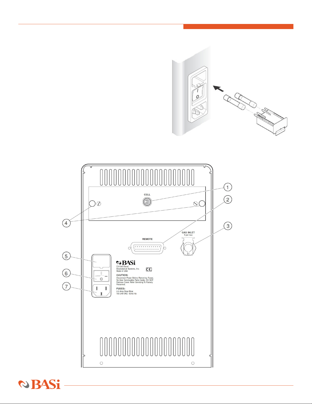
FIGURE 1. FUSE PLACEMENT
Back Panel Controls and Connections (See Figure 2)
1. Cell Lead Connector.
2. Remote Connector. 25-pin D connector for
remote control of C3
3. Gas Inlet Connector for Cell Purging. Bulkhead
fitting providing connection to external gas source
(NOTE: 5 psi maximum).
4. Thumb screws
5. Fuse Holder.
6. Power On/Off Switch.
7. Power Cord. Be sure that the 3-prong power cord is
connected to a grounded circuit.
FIGURE 2. BACK PANEL

8
CONNECTIONS
Power Cord Connection
Push the socketed (female) end of the power cord into the port located in the back panel. Before making this connection, make certain
that the power on/off switch is in the off position. This switch is labeled with a 0 and a 1. When 0 is pushed, the power is off and
when 1 is pushed, the power is on.
C3 TO EPSILON ECLIPSE
Two cables are required to connect the C3 to Epsilon EClipse. Stirring and purging can be automatically controlled. The control cable is
a 25-line ribbon cable (ER-9515) between the REMOTE connector (25-pin D, male) on the back of the C3 and the CELL STAND connector
(25-pin D, female) on the back of the epsilon (see Figure 3).
Connection of the cell lead cable is also shown in Figure 3. The cell lead cable has a stainless steel LEMO connector at each end. One
end is inserted into the CELL socket on the back of the C3. The other end is inserted into the CELL socket on the back of the BASi
electrochemical analyzer. The ends are identical; therefore, it does not matter which end is connected to the BASi electrochemical
analyzer or the C3 cell stand.
FIGURE 3. CONNECTION OF C3 TO EPSILON ECLIPSE
BASi | C3 Cell Stand SECTION 3 | INSTALLATION

9
BASi | C3 Cell StandSECTION 3 | INSTALLATION
C3 TO NON-BASI INSTRUMENTS
The C3 should work, at least in the manual mode, with virtually any instrument. Cables must be custom made by the user. The CELL
cable is modified by cutting off one of the LEMO connectors and attaching the appropriate connector for the particular instrument.
The color code for internal wires is red (auxiliary electrode lead), white (reference electrode lead), black (working electrode lead), and
bare (ground). Alternatively, if the instrument has a cell lead with alligator clips, disconnect the cell leads that are in the front panel
of the C3 and connect the alligator clips directly to the electrodes. If automatic control is desired, see Section 4 for information on
the pin outs of the REMOTE connector for construction of the proper cable.
GAS INLET CONNECTION
The C3 package contains 0.25” OD Tygon tubing and a gas line fitting. One end of the gas line fitting is barbed to fit inside the Tygon
tubing. Push the barbed end into the tubing. The other end of the fitting connects to the GAS INLET port on the rear panel of the
C3 (see Figure 4). To attach the line, simply push the connector into the port. A retaining clip will snap into place. The open end of
the Tygon tube is connected to a regulated gas supply. The inlet gas pressure must not exceed 5 psi. To remove the tube from the C3,
squeeze the retaining ring tab against the connector, then pull the tube and connector away from the C3.
Note: Please make sure that the
main gas source is always shut
off when not in use.
FIGURE 4. GAS LINE CONNECTION TO C3
CELL PLACEMENT
The C3 is designed for easy cell replacement and to accommodate both regular cells and water-jacketed cells. The cell is held in place
by the stir motor. Follow these instructions for initial cell placement:
1. Pivot the stir motor to the right.
2. Bring the cell up from underneath, around the electrodes, and seat on the cell top.
3. Pivot the stir motor back under the cell.
4. If required, the cell top height can be adjusted by loosening the cell height adjustment knob, sliding the cell top
assembly to the desired position, and tightening the knob.
5. Four 0.25” holes are in the cell top. These holes are for the working electrode, reference electrode, auxiliary electrode,
and standard addition port. Place the electrodes and port plug in the holes which are the most convenient.
PURGE/BLANKET LINES
The C3 has the ability to purge or blanket the sample solution with an inert gas. The purge line allows removal of oxygen by bubbling
an inert gas, typically nitrogen or argon, through the solution. The blanket line, on the other hand, allows maintenance of an inert
atmosphere above the sample to keep oxygen from re-entering the sample solution.
The purge/blanket lines are the two plastic tubes coming out of the cell top support block. These two lines should be pressed into the
Teflon cell top. The blanket line (the left tubing) should extend to just beyond the bottom of the cell top, while the depth of the purge
line (the right tubing) should be near the bottom of the cell vial.

10
BASi | C3 Cell Stand SECTION 3 | INSTALLATION
Note: The valve controlling the
purge/blanket lines provides users
precise control over the amount of
gas flowing through the cell stand,
and is NOT meant to be used as a
switch to completely turn off the
gas running through it. To avoid
potential gas leakage, please make
sure that BOTH the control valve is
closed all the way, as well as the
main gas source is shut off when
not in use.
ELECTRODE LEADS
The electrode lead wires extend through the front panel. The connectors are the spring-loaded, press-on type. Simply push the con-
nector over the corresponding pin in the electrode to make the connection (see Figure 5). Each wire is color coded to the electrode
it attaches. The code is:
Black . . . . . . . . .Working Electrode
White . . . . . . . . Reference Electrode
Red . . . . . . . . . . Auxiliary Electrode
Alligator clips with the appropriate pin and colored boot are included for connection to electrodes that cannot be connected to the
sockets on the cell lead.
FIGURE 5. ELECTRODE LEAD CONNECTIONS

11
BASi | C3 Cell StandSECTION 4 | OPERATION
SECTION 4. OPERATION
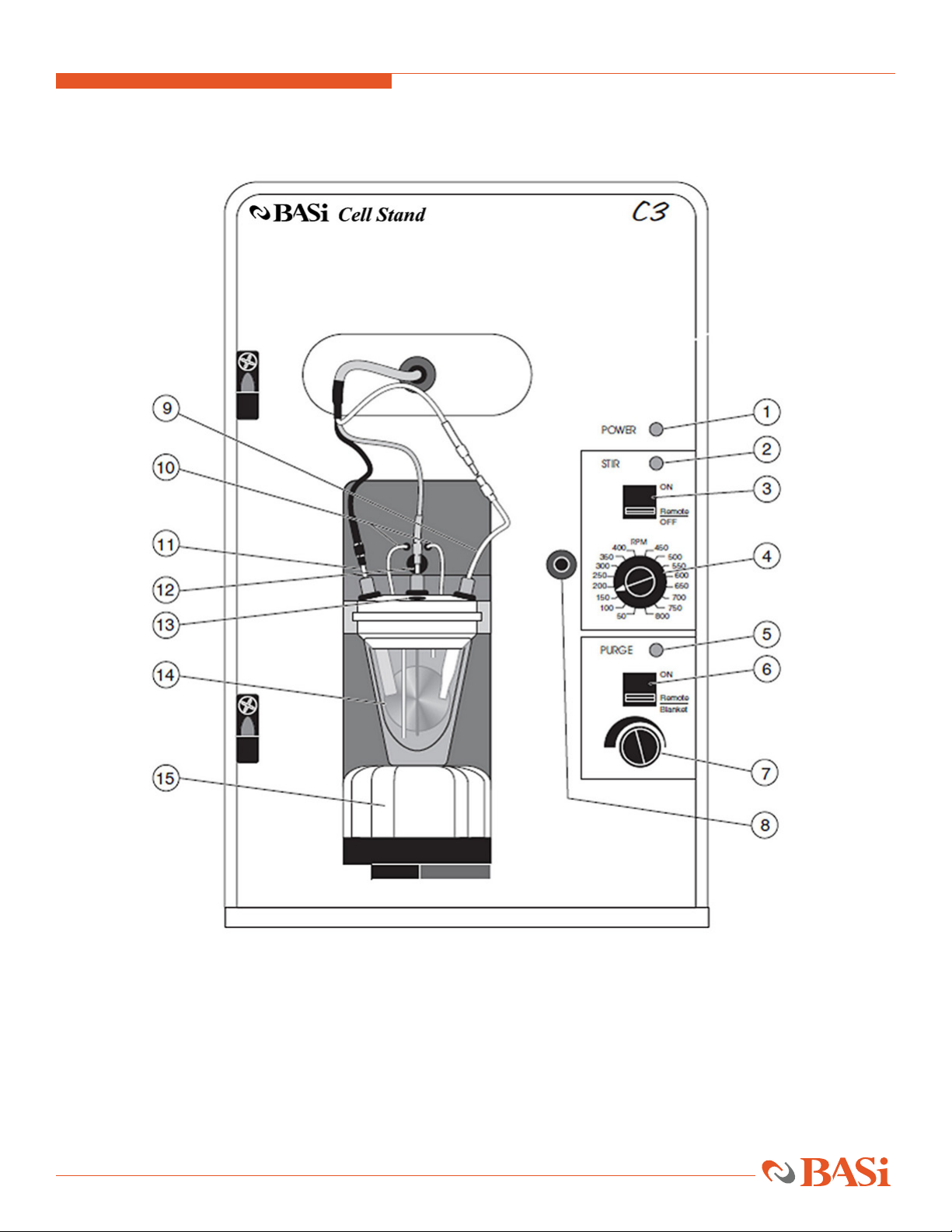
Front Panel Controls and Connections (see Figure 6)
1. Power LED. LED is lit when C3 is powered (on/off switch is located on back panel).
2. Stir-LED. LED is lit when stir is turned on, either manually or remotely.
3. Stir Control. Switch to manually control stirrer or to select remote control.
4. Stir Rate Switch. Switch for selection of one of 16 available stir rates.
5. Gas Purge LED. LED is lit when gas purge is turned on for sample vial, either manually or remotely. When LED is off
the gas flows through the blanket line.
6. Gas Purge Control. Switch to manually control gas flow to purge or blanket lines or to select for remote control.
7. Gas Purge Flow Control. Needle valve control of gas flow to purge and blanket lines.
8. Latch/Ground Socket for Faraday Cage.
9. Reference Electrode Lead. White lead connected to reference electrode.
10. Gas Purge and Blanket Lines.
11. Working Electrode Lead. Black lead connected to working electrode.
12. Auxiliary Electrode Lead. Red lead connected to platinum wire auxiliary electrode.
13. Standard Addition Port.
14. Cell Top Height Adjustment Knob.
15. Stir Motor.
12
FIGURE 6. FRONT PANEL
BASi | C3 Cell Stand SECTION 4 | OPERATION

13
REMOTE CONTROL
The remote connector of the C3 allows the stirring and gas purge functions to be controlled by an external unit. The cell stand was
specifically designed to be controlled by the appropriate commands from BASi electrochemical analyzers. These functions can be ac-
tivated by either a TTL signal or from any controller providing a contact closure to the ground. All lines are active low (negative edge
triggered) and the pin designations of the
remote connector are as follows:
Pin Description
4 digital ground
7 digital ground
8 STIR
21 PURGE
Operation of these lines is also dependent on the setting of the stir and purge switches on the front panel.
GAS PURGE
The flow rate of the gas and, whether it is directed to the purge or blanket lines, is controlled by a front panel knob and switch. When
toggled to the ON position, the gas flow is directed to the purge line and cannot be changed by remote control. When switched to
the REMOTE/BLANKET position, the gas is directed to the blanket line. It must be in this position to externally control PURGE via the
REMOTE connector on the back panel. The LED is lit when the purge function is on, either manually or remotely.
STIR
The C3 has a precisely controlled magnetic stirrer. The stirrer can be controlled either by the front panel switches or remotely. When
the stir switch is toggled to the ON position, the stirrer is on at the rate selected by the rate switch (50-800 RPM) and cannot be
remotely controlled. The REMOTE position is required for remote control of the stirrer. The LED is lit when the stir function is turned
on, either manually or remotely.
FARADAY CAGE
The C3 is supplied with an easily removed Faraday Cage. The Faraday Cage pivots on lift-off hinges. The latch grounds the Faraday Cage;
thus, the door must be completely closed for it to be effective. For many experiments, the signal generated at the electrode is large
enough that the Faraday Cage is not necessary. When small signals must be measured, the Faraday Cage will shield the cell from most
electrical interferences. Unconnected wires and water lines for temperature control passing through the wall of the
Faraday Cage may act as antennas and be sources of line frequency interference for small signals. For best results, remove any uncon-
nected wires and properly ground water lines.
REMOVAL OF CELL LEAD BOX
Remove the cell lead box by loosening the two thumb screws from the back panel (see Figure 2) and sliding the cell lead box out. When
replacing the thumb screws, tighten well to ensure proper grounding of the case.
BASi | C3 Cell StandSECTION 4 | OPERATION

14
SECTION 5. MAINTENANCE
GENERAL MAINTENANCE
The C3 is a very rugged instrument and, with proper care, should give years of service. Following is a brief list of cautions and general
maintenance considerations that will extend the lifetime of the instrument.
• Follow customary, good laboratory practices.
• Clean all spills, especially salt solutions, on or near the cabinet immediately.
• Avoid placing the unit in a corrosive atmosphere.
• Avoid dropping, shaking, or other forms of mechanical abuse to prevent loosening of components or subassemblies.
• Clean gas lines (rinse and wipe dry) after each use.
• Do not bend the auxiliary electrode (platinum wire) when removing or placing the cell vial. Repeated bending will
cause the wire to break.
TROUBLESHOOTING
BASi | C3 Cell Stand SECTION 5 | MAINTENANCE
SYMPTOM CAUSE SOLUTION
saturated signal reference tip not lower reference
contact with solution
noisy signal clogged reference replace reference
air bubble in “flick” reference until bubbles
reference tip reference tip are at top
vibrations place on pad to dampen vibration
electrical line use Faraday Cage
frequency interference
spikes in power line power from a different circuit
variation in temperature variation use water-jacketed cell
peak height

15
SERVICE PROCEDURE
There are no user-serviceable electronic parts in this unit and all service requests should be referred to BASi service personnel. In
certain cases, BASi will provide electronic schematics and service procedures to qualified electronic maintenance facilities, but only
upon written request and then only with the approval of the Service Coordinator.
If a problem arises and appears to be equipment-oriented, call BASi at (765) 463-4527 ext 5809,
or visit https://www.basinc.com/ask and fill-out the form. You can also email service@basinc.com.
BASi | C3 Cell StandSECTION 5 | MAINTENANCE
Table of contents
Popular Laboratory Equipment manuals by other brands

Cooper Surgical
Cooper Surgical RI WITNESS user manual

Cooper Surgical
Cooper Surgical K-Systems R65 user manual

J.P. SELECTA
J.P. SELECTA PLAC-CENTER manual

Thermo Forma
Thermo Forma 3920 Operating and maintenance manual

SereneLife
SereneLife SLUVDISB50 user manual

PerkinElmer
PerkinElmer Clarus SQ 8 MS Series Hardware guide


