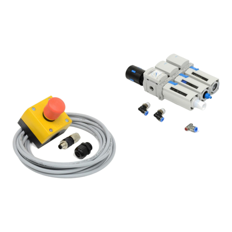
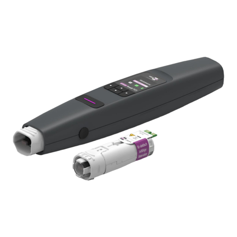
Relyon plasma piezobrush PZ2-i User manual

EN Operating instructions for piezobrush®PZ2-i integration unit
DE Betriebsanleitung piezobrush®PZ2-i Integrationseinheit
FR Notice d'utilisation de l'unité d'intégration piezobrush® PZ2-i
ES Manual de instrucciones de la unidad de integración
piezobrush® PZ2-i
BA-PZ2-i_ML / F0353800 / 04_17
www.relyon-plasma.com
All rights reserved


Operating instructions for
piezobrush®PZ2-i integration unit

Thank you for buying a Relyon Plasma GmbH branded product. To get the best from your machine, please
read these instructions carefully.
Important!
Read these instructions carefully before assembling, installing and starting up the machine!
Always follow the safety instructions! Failure to follow the safety instructions may result in accidents,
serious injury and serious damage to the machine.
Train your staff! The operator/user is responsible for ensuring that personnel have fully understood the
operation of the machine and the safety requirements.
© Copyright Relyon Plasma GmbH 2017.
All rights reserved.
Text, images and graphics as well as their layout are protected by copyright and other protective laws. Unauthorised
copying and distribution of this document and the utilisation and communication of its contents are strictly prohibited
unless expressly authorised. Offenders will be held liable for the payment of damages. All rights reserved in the event of
the grant of a patent, utility model or design.
Original operating
instructions

Table of contents
5
1Safety ............................................................................................................................................................6
1.1 Residual risks....................................................................................................................................6
1.2 Information and obligations for the operator.....................................................................................7
1.3 Impermissible operating conditions...................................................................................................7
1.4 Emissions..........................................................................................................................................7
2Description of machine..................................................................................................................................8
2.1 Correct use........................................................................................................................................8
2.2 Scope of delivery...............................................................................................................................8
2.3 Device overview................................................................................................................................9
2.4 Connecting lead assignment...........................................................................................................10
2.5 Cap rail power supply unit assignment ...........................................................................................10
3Technical data.............................................................................................................................................11
4Transport/storage........................................................................................................................................11
5Installation ...................................................................................................................................................12
6Operation.....................................................................................................................................................13
7Taking out of service ...................................................................................................................................13
8Maintenance................................................................................................................................................13
8.1 Cleaning..........................................................................................................................................13
8.2 Changing the nozzle .......................................................................................................................14
9Troubleshooting...........................................................................................................................................14
10 Environment ................................................................................................................................................15
10.1 Disposal ..........................................................................................................................................15
11 Conformity / standards ................................................................................................................................15
11.1 CE ...................................................................................................................................................15
11.2 Product standards...........................................................................................................................15
12 Spare parts..................................................................................................................................................16

Safety
6
1Safety
1.1 Residual risks
This device has been manufactured in accordance with the current state of the art.
However, it is impossible to eliminate residual risks.
Always adhere to the following safety instructions:
Caution –electrical voltage!
Only use the power supply unit provided.
Danger due to line voltage. If the power supply unit is visibly damaged:
- Do not start up the machine.
- Replace the damaged parts or have them repaired by a qualified person.
Attention –emissions!
Dangerous amounts of the reaction gas ozone (O3) may be produced during machine
operation.
- An amount of ozone in excess of 0.2 mg/m³ may be produced.
- Note that national health and safety measures must be observed when
operating the device.
- Only use the device in well vented areas or in conjunction with a suitable
exhaust system.
Attention –damage to device!
The plasma generator may be damaged if it is operated without gas flow.
This would interrupt the supply of cooling medium required in operation.
Never touch the piezo crystal on the front side of the machine with sharp-edged objects.
This component may be damaged by improper handling.
Protect the plasma generator from falls or other hard impacts which may damage the
electronics or piezo crystal.

Safety
7
1.2 Information and obligations for the operator
•The system may emit interference.
- The device has been tested in accordance with EMC legislation.
- The operator must verify and assure electromagnetic compatibility with other
electrical and electronic equipment in the immediate vicinity of the system.
•Ensure that:
- Operating personnel have read and understood these operating instructions.
- Anyone working near the machine is made aware of the dangers and is provided
with the necessary protective equipment.
- Repairs are only carried out by qualified persons.
•In particular, make operating personnel aware of the safety instructions in this
document.
•Always keep the system in fully functional condition.
•Any modifications made to the machine will invalidate the operating licence and the
warranty. Exception: Such modifications are expressly authorised by the manufacturer.
1.3 Impermissible operating conditions
The machine must not be operated under the following conditions:
•In explosive (Ex) zones
•In areas with severe build-up of dust
•In environments where the air humidity is too high (see technical data, page 11)
•At altitudes of more than 2,000 m above sea level
•Where there are strong vibrations
1.4 Emissions
The plasma generator produces the following emissions:
•Certain quantities of ozone (O3). The workplace limit value may be exceeded. Example:
Plasma gas
Gas flow
Ozone
Air
15 l/min
< 0,18 g/h
Nitrogen
15 l/min
< 0,13 g/h
Note!
As a precautionary measure, we recommend using an exhaust system with a flow volume
of approx. 10 times the amount of gas flow through the device in the immediate vicinity of
the plasma outlet.

Description of machine
8
2Description of machine
2.1 Correct use
The piezobrush® PZ2-i is an integration unit for generating cold discharge, hereafter
referred to as plasma. It is intended to be mounted in stationary machines or in positioning
units and is used for pre-treating various material surfaces prior to process steps such as
adhering or printing. The cleaning effect of the plasma can also be utilized.
Only use the device for the intended purposes. Failure to do so may restrict product
liability.
2.2 Scope of delivery
The scope of delivery includes the following components:
•Plasma generator
•Standard nozzle (pre-assembled)
•Cap rail power supply unit
•Connecting lead (length 10 m)
•Operating instructions
Not included:
•Special nozzles
•Gas hose (outer diameter of hose Ø 4 mm)

Description of machine
9
2.3 Device overview
The individual parts of the device are depicted and labelled in the diagram below. These
terms are used at corresponding points in the operating instructions.
No.
Component designation
1
Piezo crystal (internal)
2
Nozzle insert (standard nozzle)
3
Lock button for nozzle insert (on both sides)
4
Name plate
5
Connecting lead
6
Connection for gas hose (for hose outer diameter Ø 4 mm)
7
Socket for connecting lead
8
Mounting block with M4 drill holes
9
Cap rail 15 V DC power supply unit
4
8
6
7
3
2
1
5
9

Description of machine
10
2.4 Connecting lead assignment
The leads of the connecting lead included in delivery are to be assigned as follows:
Attention –damage to device!
Pins 3 and 4 are not potential-free. A 5 V DC signal is used to control the device. Only
connect potential-free switches, such as relays, to pins 3 and 4. Errors at pins 3 and 4
may break the device.
2.5 Cap rail power supply unit assignment
The connections of the cap rail power supply unit are to be assigned as followed:
Caution –electrical voltage!
Only use the power supply unit provided.
The wires may only be connected to the power supply unit or control system by
authorised electrically skilled persons!
Danger due to line voltage. If the power supply unit is visibly damaged:
- Do not start up the machine.
- Replace the damaged parts or have them repaired by a qualified person.
V -
V +
L
N

Technical data
11
3Technical data
Plasma generator electrical data
•Supply voltage
15 V DC
•Power consumption
max. 30 W
•Model
Integration unit with gas connection
Cap rail power supply unit electrical data
•Supply voltage
100- 240 V AC; 50/60 Hz
•Output voltage
15 V DC
•Power consumption
max. 40 W
•Model
Cap rail power supply unit with screw terminals
Plasma generator dimensions
•Weight
180 g (without power supply unit and cable)
•Length
228 mm (without cable)
•Width
36 mm
•Height
51 mm
•Cable length
10 m
Typical application parameters
•Plasma temperature
< 50 °C
•Distance for treatment
2 –5 mm
•Width for treatment
5 –20 mm
•Speed
10 –50 mm/s
Operating conditions
•Air humidity
< 80% rel. (non-condensing)
•Temperature
10 –40 °C; 50 –104 °F
Storage conditions
•Air humidity
< 80% rel. (non-condensing)
•Temperature
0 –60 °C; 32 –140 °F
Gas connection
•Gas types
Compressed air (purified, oil- and lubricant-free)
Nitrogen (particle- and oil-free technical gases)
Additional gas types only after approval from Relyon Plasma.
•Gas flow rate
10 –25 l/min
•Quality
Compressed air 1.4.1 in accordance with ISO 8573.1
Nitrogen 2.8 (N2) in accordance with DIN EN ISO 14175:N1
•Connection
Hose outer diameter Ø 4 mm (quick coupling)
4Transport/storage
•Store the device in a dry place. This will prevent the electrical contacts from corroding. It
is best to use the case provided for storage and transport.
•Protect the device from dirt and foreign objects.
•Protect the device from falls or other hard impacts.

Installation
12
5Installation
To install the device, perform the following steps in the specified order:
1. Mount the plasma generator onto a stable surface
securely using the two M4 tapped holes. The device
can be positioned in any spatial direction.
2. Attach the connecting lead as described in Section 2.4
and connect the lead with the accompanying power
supply unit and your control system.
3. Connect the connecting lead to the corresponding
socket of the plasma generator and tighten the cap nut
hand-tight.
4. Connect a suitable gas hose with outer diameter Ø 4
mm to the corresponding gas connection on the
plasma generator and check that the gas hose is
firmly positioned.
The plasma generator is installed.
Attention –damage to device!
The plasma generator may be damaged if it is operated without gas flow.
This would interrupt the supply of cooling medium required in operation.
-Never switch on the plasma generator before the gas stream
(2 seconds) is switched on.
The plasma generator can be damaged if there are conductive
objects closer than 60 mm around the front third of the plasma generator. Exception:
Substrates in front of the nozzle when using the near-field nozzle.
X
X

Operation
13
6Operation
•Make sure that there is sufficient gas flow in order to guarantee the cooling of the
device.
•In order to generate plasma, switch on the device using the switching signal of your
control system while connecting pins 3 and 4 electrically.
While plasma is being generated, do not reach into the working area. This may interrupt
plasma discharge and cause skin irritation or mild pain.
Note!
The plasma generator is not designed for treating metallic or conductive substrates with
the accompanying standard nozzle. Such substrates may negatively affect the plasma
discharge and damage the device.
Conductive substrates may only be treated using specifically designed nozzles (e.g. near-
field nozzle).
Do not use the plasma generator for sensitive electronic components. The plasma
discharge may damage such components under certain circumstances.
7Taking out of service
•Switch off the device using the switching signal of your control system in order to end
plasma generation. To do so, disconnect the electrical connection between pins 3 and
4.
8Maintenance
8.1 Cleaning
Only clean the outside of the plasma generator.
•Ensure that the plasma generator is disconnected from the power supply.
•Only clean the plasma generator with a cloth dampened in water. Do not use solvents
to clean the plasma generator!

Troubleshooting
14
8.2 Changing the nozzle
Proceed as follows:
•Make sure that the plasma generator is switched off.
•Press the lock buttons on both sides of the nozzle insert.
•Pull out the nozzle insert from the housing.
•Insert the new nozzle insert in the housing. If necessary, begin by pressing the lock
buttons and do not angle the insert.
•Apply a little pressure and slide the nozzle insert until it engages in the lock position.
Attention –damage to device!
Never touch the piezo crystal on the front side of the machine with sharp-edged objects.
This component may be damaged by improper handling.
9Troubleshooting
Fault/error
Cause
Rectification
Device cannot be activated or
plasma runs out during
operation
Faulty power supply.
(provided by customer)
Defective power supply unit
Replace power supply unit
Power supply unit connected
incorrectly
Check “DC OK” lamp on the
power supply unit, check
connection assignment
Mains fuse was triggered
Check mains fuse.
Mains plug not making contact
correctly.
Check seat of mains plug.
Mains plug is defective.
Replace mains plug.
There is an internal error.
De-energise the device. Switch
on again.
Piezo crystal broken, the
plasma generator is defective.
Contact customer service.
Shutdown due to overheating
Allow the plasma generator to
cool. Make sure that there is
sufficient gas flow.
If these actions do not remedy the problem, please contact customer service.

Environment
15
10 Environment
10.1 Disposal
Be mindful of the environment.
Used electrical and electronic equipment must not be disposed of along with normal
waste.
- The device contains valuable materials that can be recycled. Take the device to a
suitable collection point.
11 Conformity / standards
11.1 CE
We declare that this product conforms to CE standards.
The product name can be found on the device's name plate.
11.2 Product standards
The device satisfies the following requirements and standards:
EMC
EN 55011:2009+A1:2010 Group 1 Class A
EN 61000-6-2:2005+AC:2005
EN 61000-3-2:2006+A1:2009+A2:2009
EN 61000-3-3:2013
LVD
EN 61010-1:2010
RoHS
EN 50581:2012
Protection class IP20
IEC 60529

16
12 Spare parts
Item number
Description
1000269202
Standard nozzle insert
1000617700
Connecting lead
1000618200
Cap rail power supply
Relyon Plasma GmbH
Weidener Strasse 16
93057 Regensburg
Germany
Phone: +49 941 60098-0
Fax: +49 941 60098-100
E-mail: info@relyon-plasma.com
http://www.relyon-plasma.com
Service hotline: +49 941 60098-120

Spare parts
17

18

Spare parts
19
Betriebsanleitung
piezobrush®PZ2-i
Integrationseinheit

20
Wir freuen uns, dass Sie sich für ein Markengerät der Firma Relyon Plasma GmbH entschieden haben und
danken Ihnen für das entgegengebrachte Vertrauen. Um das Gerät optimal nutzen zu können, lesen Sie bitte
die Betriebsanleitung sorgfältig durch.
Wichtiger Hinweis!
Lesen Sie diese Anleitung unbedingt vor Montage, Installation und Inbetriebnahme
gründlich durch!
Beachten Sie unbedingt die Sicherheitshinweise! Nichtbeachten der Sicherheitshinweise kann zu Unfällen
führen und schwere Schädigungen an Mensch und Maschine verursachen.
Unterweisen Sie das Personal! Der Betreiber/Benutzer ist dafür verantwortlich, dass das Personal die
Bedienung des Gerätes und die Sicherheitsbestimmungen vollständig verstanden hat.
© Copyright Relyon Plasma GmbH 2017.
Alle Rechte vorbehalten. All rights reserved.
Texte, Bilder und Grafiken sowie deren Anordnung unterliegen dem Schutz des Urheberrechts und anderer
Schutzgesetze. Weitergabe sowie Vervielfältigung dieses Dokuments, Verwertung und Mitteilung seines Inhalts sind
verboten, soweit nicht ausdrücklich gestattet. Zuwiderhandlungen verpflichten zu Schadenersatz. Alle Rechte für den
Fall der Patent-, Gebrauchsmuster- oder Geschmacksmustereintragung vorbehalten.
Originalbetriebsanleitung
Table of contents
Languages:
Other Relyon plasma Laboratory Equipment manuals
Popular Laboratory Equipment manuals by other brands

Metrohm
Metrohm 663 VA Stand manual

Gardner Denver
Gardner Denver WELCH LVS 600 T Operation manual

Thermo Scientific
Thermo Scientific Precision U01366 user manual

REPLIGEN
REPLIGEN KrosFlo KTF user guide

Pacific Image Electronics
Pacific Image Electronics Glite 965BW user manual

BIO RAD
BIO RAD NGC quick guide

Rohde & Schwarz
Rohde & Schwarz Smart Instruments SM300 Programming guide

CAMAG
CAMAG DBS-MS 500 instruction manual

Socket
Socket S840 manual

PASCO
PASCO ME-9207B Instruction manual and experiment guide

Greiner Bio-One
Greiner Bio-One MULTI-MAGPEN 657896 Instructions for use

Bego
Bego Nautilus CC plus Translation of the original instructions