Thermo Forma 3920 Operating instructions

Model 3920
29 cu. ft. Capacity
Environmental Chamber
Operating and Maintenance Manual
Manual No: 7033920 Rev. 12

Model 3920 _________________________________________________________________________________
i
Read This Instruction Manual.
Failure to read, understand and follow the instructions in
this manual may result in damage to the unit, injury to operat-
ing personnel, and poor equipment performance.
CAUTION! All internal adjustments and maintenance must
be performed by qualified service personnel.
Refer to the serial tag on the back of this manual.
The material in this manual is for information purposes only.
The contents and the product it describes are subject to change
without notice. Thermo Forma makes no representations or war-
ranties with respect to this manual. In no event shall Thermo
Forma be held liable for any damages, direct or incidental, aris-
ing out of or related to the use of this manual.
MANUAL NUMBER 7033920
12 20479/IN-3013 5/29/02 Added Auto IR CO2option as a standard accessory aks
-- 20480/PIP-041 11/21/01 Removed reference to p-trap (190467), no longer on parts list ccs
11 20342/PIP-012 10/3/01 Revised electrical schematics aks
10 19935 5/8/01 Added 3920-71 drawing aks
9 IN-2858 3/13/01 Revised control panel access and revised electrical schematic aks
8 19617 12/13/00 New door - updated electrical schematics ccs
7 19207/IN-2827 6/28/00 Revised electrical schematics and parts list (250200 to 300345 contactor) ccs
6 -- 4/20/00 Quark format ccs
5 18896/SI-7773 2/8/00 New 3920 schematic - wiring harness, 430305 ccs
4 -- 11/22/99 Corrected Section 2.9 Offset Configuration ccs
3 17861/IN-2439 8/10/99 Updated schematics for CSA ccp
REV ECR/ECN DATE DESCRIPTION By
Model 3920 _________________________________________________________________________________
ii
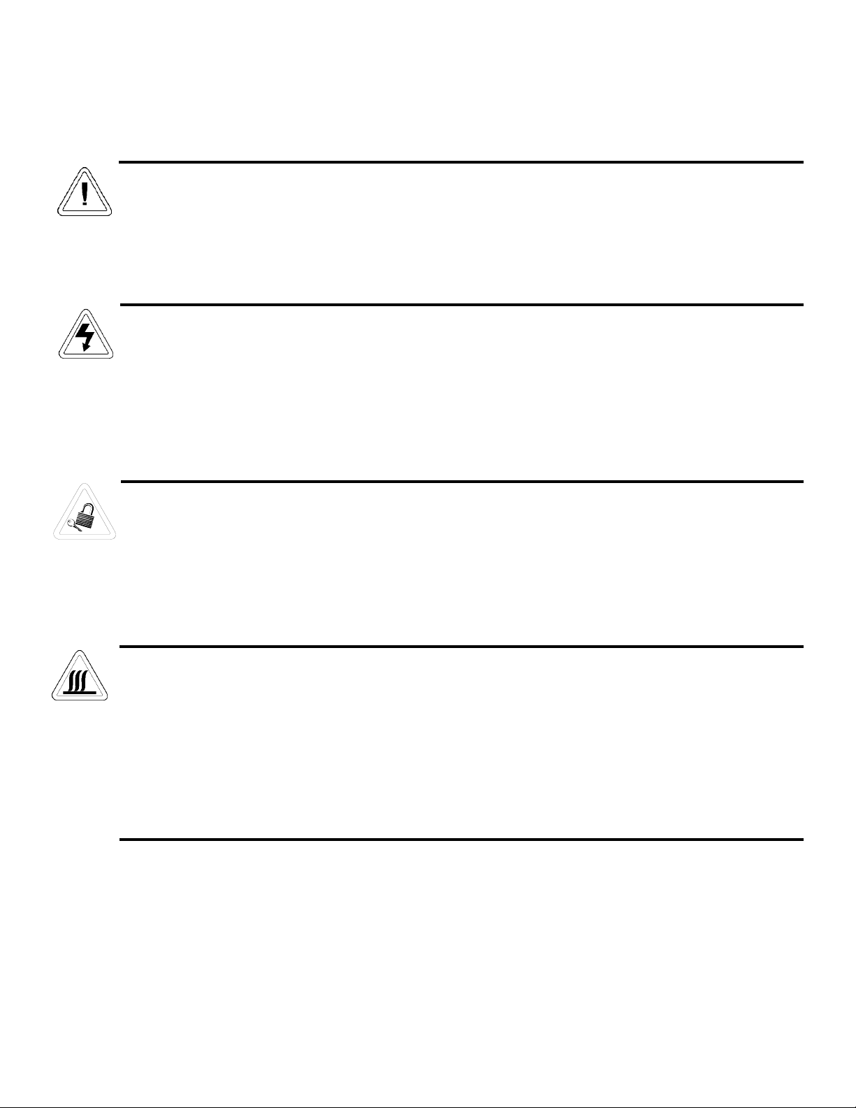
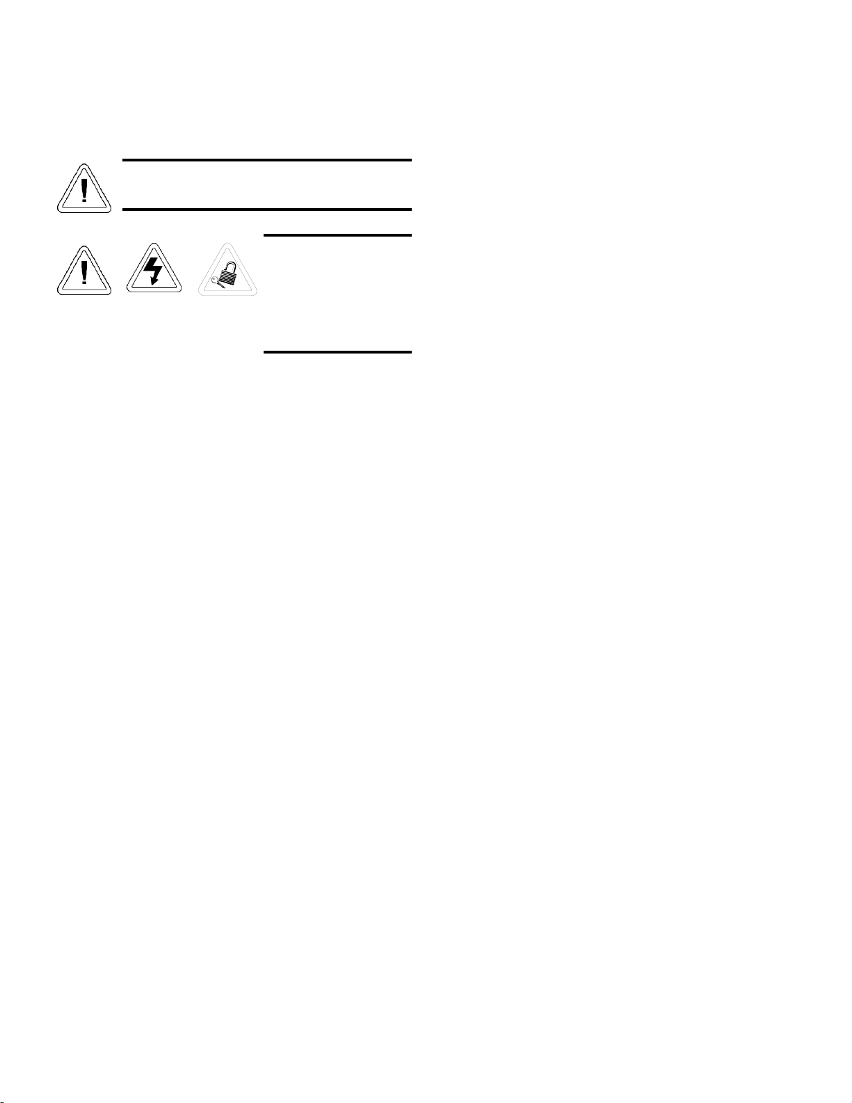
Important operating and/or maintenance instructions. Read the accompanying text carefully.
Ce symbole attire l'attention de l'utilisateur sur des instructions importantes de fonctionnement et/ou d'entretien. Il
peut être utilisé seul ou avec d'autres symboles de sécurité. Lire attentivement le texte d'accompagnement.
Wichtige Betriebs- und/oder Wartungshinweise. Lesen Sie den nachfolgenden Text sorgfältig.
Importante instruccions de operacion y/o mantenimiento. Lea el texto acompanante cuidadosamente.
Potential electrical hazards. Only qualified persons should perform procedures associated with this symbol.
Ce symbole attire l'attention de l'utilisateur sur des risques électriques potentiels. Seules des personnes qualifiées
doivent appliquer les instructions et les procédures associées à ce symbole.
Gefahr von Stromschlägen. Nur qualifizierte Personen sollten die Tätigkeiten ausführen, die mit diesem Symbol beze-
ichnet sind.
Potencial de riesgos electricos. Solo personas das capacitadadas deben ejecutar los procedimientos asociadas con este
simbulo.
Equipment being maintained or serviced must be turned off and locked off to prevent possible injury.
Risques potentiels liés à l'énergie. L'équipement en entretien ou en maintenance doit être éteint et mis sous clé pour
éviter des blessures possibles.
Geräte, an denen Wartungs- oder Servicearbeiten durchgeführt werden, müssen abgeschaltet und abgeschlossen wer-
den, um Verletzungen zu vermeiden.
El equipo recibiendo servicio o mantenimiento debe ser apagado y segurado para prevenir danos.
Hot surface(s) present which may cause burns to unprotected skin, or to materials which may be damaged by elevated
temperatures.
Présence de surface(s) chaude(s) pouvant causer des brûlures sur la peau non protégée, ou sur des matières pouvant
être endommagées par des températures élevées.
Heiße Oberfläche(n) können ungeschützter Haut Verbrennungen zufügen oder Schäden an Materialien verursachen,
die nicht hitzebeständig sind.
Superficias calientes que pueden causar quemaduras a piel sin proteccion o a materiales que pueden estar danados
por elevadas temperaturas.
√ Always use the proper protective equipment (clothing, gloves, goggles, etc.)
√ Always dissapate extreme cold or heat and waer protective clothing.
√ Always follow good hygiene practices.
√ Each individual is responsible for his or her own safety.

Model 3920 _________________________________________________________________________________
iii

Model 3920 _________________________________________________________________________________
iv
Table of Contents
Section 1 - Receiving . . . . . . . . . . . . . . . . . . . . . . . . . . . .2 - 1
1.1 Preliminary Inspection . . . . . . . . . . . . . . . . . . . . . . .2 - 1
1.2 Visible Loss or Damage . . . . . . . . . . . . . . . . . . . . . .2 - 1
1.3 Responsibility for Shipping Damage . . . . . . . . . . . .2 - 1
Section 2 - Installation and Start-Up . . . . . . . . . . . . . . . .2 - 1
2.1 Location . . . . . . . . . . . . . . . . . . . . . . . . . . . . . . . . . . .2 - 1
2.2 Attaching the Drain Connections . . . . . . . . . . . . . . . .2 - 1
2.3 RS-232 Output Interface & Remote Alarm Connector 2 - 1
a. Remote Alarm Contacts . . . . . . . . . . . . . . . . . . . .2 - 2
2.4 Power Connection . . . . . . . . . . . . . . . . . . . . . . . . . . .2 - 2
2.5 Start-Up Procedure . . . . . . . . . . . . . . . . . . . . . . . . . .2 - 2
2.6 Setting the Overtemp Safety Thermostat . . . . . . . . .2 - 2
2.7 Setting the Undertemp Safety Thermostat . . . . . . . .2 - 2
2.8 Preparing the (Optional) CoBex Recorder . . . . . . . .2 - 3
a. Installing the Battery . . . . . . . . . . . . . . . . . . . . . . .2 - 3
b. Changing the Chart Paper . . . . . . . . . . . . . . . . . . .2 - 3
c. Changing the Pen . . . . . . . . . . . . . . . . . . . . . . . . .2 - 3
d. Calibrating the Chart Recorder . . . . . . . . . . . . . . .2 - 3
2.9 Offset Calibration . . . . . . . . . . . . . . . . . . . . . . . . . . .2 - 4
2.10 Honeywell Recorder . . . . . . . . . . . . . . . . . . . . . . . . .2 - 4
2.11 Controller Configuration . . . . . . . . . . . . . . . . . . . . . .2 - 4
2.12 1900140 IR CO2Option . . . . . . . . . . . . . . . . . . . . . .2 - 5
a. Connecting the CO2Source . . . . . . . . . . . . . . . . . .2 - 5
b. Setting the CO2Content . . . . . . . . . . . . . . . . . . . . .2 - 5
c. CO2Controller Calibration . . . . . . . . . . . . . . . . . . .2 - 5
d. CO2Control and Indicators . . . . . . . . . . . . . . . . . .2 - 5
Section 3 - Control Panel Operation . . . . . . . . . . . . . . . .3 - 1
3.1 The 3920 Control Panel . . . . . . . . . . . . . . . . . . . . . . .3 - 1
3.2 Setting the Operating Temperature (Figure 3-3) . . . .3 - 2
3.3 Programming the controller . . . . . . . . . . . . . . . . . . .3 - 2
a. Removing the mechanical lockout . . . . . . . . . . . .3 - 2
b. Removing the Software Lockout . . . . . . . . . . . . .3 - 2
3.4 Air Exchange Ventilator Caps . . . . . . . . . . . . . . . . . .4 - 1
Section 4 - Routine Maintenance . . . . . . . . . . . . . . . . . . .4 - 1
4.1 Cleaning the Incubator . . . . . . . . . . . . . . . . . . . . . . . .4 - 1
Section 5 - Service . . . . . . . . . . . . . . . . . . . . . . . . . . . . . .5 - 1
5.1 Access to the Electrical Components . . . . . . . . . . . .5 - 1
5.2 Replacing Overtemp/Undertemp Probe & Thermostat 5 - 1
5.3 Replacing the Temperature Sensor . . . . . . . . . . . . . .5 - 2
5.4 Removing the Top Section . . . . . . . . . . . . . . . . . . . . .5 - 2
5.5 Setting the Door Heater Control . . . . . . . . . . . . . . . . .5 - 3
Section 6 – Specifications . . . . . . . . . . . . . . . . . . . . . . . .6 - 1
Section 7 - Parts List . . . . . . . . . . . . . . . . . . . . . . . . . . . .7 - 1
Section 8 - Schematics . . . . . . . . . . . . . . . . . . . . . . . . . . .8 - 1

Section 1 - Receiving
1.1 Preliminary Inspection
This item was thoroughly inspected and carefully packed
prior to shipment. All necessary precautions were taken to
ensure safe arrival of the merchandise at its destination.
Immediately upon receipt, before the unit is moved from the
receiving area, carefully examine the shipment for loss or dam-
age. Unpack the shipment and inspect both interior and exterior
for any in-transit damage.
1.2 Visible Loss or Damage
If any loss or damage is discovered, note any discrepancies
on the delivery receipt. Failure to adequately describe such evi-
dence of loss or damage may result in the carrier refusing to
honor a damage claim. Immediately call the delivering carrier
and request that their representative perform an inspection. Do
not discard any of the packing material and under no circum-
stances, move the shipment from the receiving area.
1.3 Responsibility for Shipping Damage
For products shipped F.O.B. Marietta, Ohio, the responsi-
bility of Thermo Forma ends when the merchandise is loaded
onto the carrier’s vehicle.
On F.O.B. Destination shipments, Thermo Forma and the
carrier’s responsibility ends when your Receiving Department
personnel sign a free and clear delivery receipt.
Whenever possible, Thermo Forma will assist in settling
claims for loss or in-transit damage.
Section 2 - Installation and Start-Up
2.1 Location
Locate the unit on a firm, level surface in an area of mini-
mum ambient temperature fluctuation. A minimum of 12 inches
clearance is required at the top of the incubator and a minimum
of 3 inches clearance is required at the rear of the incubator to
facilitate adequate airflow around the refrigeration system.
2.2 Attaching the Drain Connections
The cabinet’s 3/8” MPT drain line connection is located on
the rear (lower left side) of the cabinet.
To install the drain connection, push a piece of 3/8” ID tub-
ing onto the cabinet drain connection and direct the tubing to a
convenient drain. Install a hose clamp on the tubing, if desired.
2.3 RS-232 Output Interface and Remote Alarm
Connector
The Model 3920 is equipped with an RS-232 Serial
Communication Interface for the remote transmission of tem-
perature data. The remote alarm connections are also included
on the terminal strip.
Figure 2-2
Terminal Pin Descriptions, RS-232 (1-6) and
Remote Alarm Connections (7-9)
Model 3920__________________________________________________________________Installation and Start-Up
2 - 1
123456789
Terminal Strip Connections
Temperature
RS 232
Remote Alarm
(Shown in alarm)
TRANSMIT
COMMON
COMMON
N.O.
N.C.
RECEIVE

a. Remote Alarm Contacts
Remote alarm connections are also included on the termi-
nal strip (Figure 2-2) providing Normally Open (N.O.) and
Normally Closed (N.C.) contacts. COM is the Common termi-
nal. The remote alarm will activate when either the incubator’s
temperature goes out of the set alarm limits.
2.4 Power Connection
See the serial tag on the side of the unit for electrical spec-
ifications, or refer to the electrical schematics at the end of this
manual.
Connect the incubator to a grounded, dedicated
circuit. The power cord connector is the mains
disconnect device for the incubator. Position the
incubator so the unit can be easily disconnected.
For Model 3920, plug the provided 10 ft. power cord with
the NEMA 5-20 plug into the power outlet connection on the
back of the cabinet, then into the grounded dedicated electrical
circuit.
2.5 Start-Up Procedure
Preset the controls as follows:
Overtemp Safety Thermostat . . . . . . . . . . . .(Fully Clockwise)
Undertemp Safety Thermostat . . . . .(Fully Counterclockwise)
Main Power Switch . . . . . . . . . . . . . . . . . . . . . . . . . . . . . . .ON
Temperature Controller . . . . . . . . . . . . . . . . . .Desired Setpoint
Door Heater . . . . . . . . . . . . . . . . . . . . . . . . . .40% (factory set)
Turn the Main Power switch on. The Power indicator and
Heat indicator will light. Turn the Refrigeration switch on and
the indicator will light.
The compressor and refrigeration lights will not
come on if the chamber temperature is within
±4°C of the temperature controller.
2.6 Setting the Overtemp Safety Thermostat
Allow the chamber temperature to stabilize, then set the
overtemp safety thermostat as follows:
1. Turn the overtemp control knob slowly counterclockwise
until the audible alarm sounds and the overtemp indica-
tor lights.
2. Turn the overtemp control knob clockwise approximately
two units on the scale. The alarm should be silenced and
the overtemp indicator light should go out.
The overtemp safety thermostat is now set a few degrees
above the control temperature setpoint. When the chamber tem-
perature rises to the overtemp control point, the alarm system
will activate, power to the heaters will shut off, and the cham-
ber temperature will be maintained at the overtemp control
point.
When an overtemp condition occurs, the cause must be
determined and corrected before normal operation under the
main temperature controller can be resumed.
Note: When the chamber temperature control setpoint is
changed, the overtemp safety thermostat must be reset to
accommodate the change.
2.7 Setting the Undertemp Safety Thermostat
Allow the chamber temperature to stabilize, then set the
undertemp safety thermostat as follows:
1. Turn the undertemp control knob slowly clockwise until
the audible alarm sounds and the undertemp indicator
lights.
2. Turn the undertemp control knob counterclockwise
approximately two units on the scale. The alarm should
be silenced and the undertemp indicator light should go
out.
The undertemp safety thermostat is now set a few degrees
below the control temperature setpoint. When the chamber tem-
perature drops to the undertemp control point, the alarm system
will activate, power to the compressor will shut off, and the
chamber temperature will be maintained at the undertemp con-
trol point.
When an undertemp condition occurs, the cause must be
determined and corrected before normal operation under the
main temperature controller can be resumed.
Note: When the chamber temperature control setpoint is
changed, the undertemp safety thermostat must be reset to
accommodate the change.
Model 3920__________________________________________________________________Installation and Start-Up
2 - 2

2.8 Preparing the (Optional) CoBex Recorder
a. Installing the Battery
The seven-day circular chart recorder is located on the
front of the incubator cabinet and is protected by a glass door.
To prepare the recorder for operation, open the glass door
and snap the connector onto the 9-volt battery as shown in
Figure 2-3. If the unit is operating, the green LED lights steady.
If the unit is not turned on, the LED blinks.
Figure 2-3
If the battery is weak or not connected, the green LED will
flash. If power is lost to the cabinet, the LED will also flash.
When replacing the 9-volt battery, use only an alkaline style
battery. Dispose of the old battery following established envi-
ronmental practices.
b. Changing the Chart Paper
1. Press the Change Chart button (#3) and hold it for 1 sec-
ond until the pen begins to move to the left of the chart.
See Figure 2-3.
2. Remove the existing chart by unscrewing the center
knob securing it.
3. Install the new chart, positioning it so that the correct
time line coincides with the time line groove on the
chart plate.
4. Replace the center knob and screw it tightly against the
chart.
c. Changing the Pen
1. Using a small flat blade screwdriver, loosen the 2 screws
holding the pen arm and remove the pen and arm as an
assembly.
2. Unsnap the plastic hinge securing the pen. Remove and
discard the old pen.
3. Install the new pen by snapping the hinge securely
around the pen arm.
4. Re-install the pen assembly by sliding the pen arm under
the screws, positioning the pen tip in the time line
groove. Tighten the screws.
5. Push the Chart Change button (Figure 2-4) and hold it
for 1 second until the pen begins to move back onto the
chart.
Note: Make sure that the pen is marking on the chart. It may
be necessary to gently lift the pen onto the chart paper.
d. Calibrating the Chart Recorder
1. Place an accurate thermometer(s) in the chamber next to
the recorder’s probe(s). After about three minutes, com-
pare the thermometer with the chart recorder. For 2 pen
operations, also compare the second thermometer.
Note: For 2 pen operations, first select the pen you wish to cali-
brate. Hold down the #1 arrow for the red (#1) pen or the #2
arrow for the blue (#2) pen, until the light goes out. Refer to
Figure 2-4. Then adjust as necessary.
If an adjustment is necessary, press
either the #1 or #2 button to move the
pen left or right. The button must be
held about five seconds before the pen
begins to move. Release the button
when the pen matches the thermometer.
Model 3920__________________________________________________________________Installation and Start-Up
2 - 3
12
3
time line
groove
Press to
change
chart
Slotted screws
(loosen only)
9-volt battery
Figure 2-4

2.9 Offset Calibration
It may be necessary to calibrate the temperature controller
to match an independent temperature sensor. To do so, follow
the next few steps.
1. Suspend an independent, calibrated sensor(s) in the cen-
ter of the interior chamber.
2. Allow approximately 30 minutes for the incubator to
stabilize.
3. Turn off the main power switch.
4. Wear a grounding wrist strap to avoid damaging any of
the electrical components.
Figure 2-5
5. Remove the 982 controller module(s) by pressing in the
four retaining tabs, two on the right side, two on the left
side. Refer to Figure 2-5. Pull the controller module out
by gently rocking it from side to side.
6. Looking at the top and right side of the controller mod-
ule, locate the red DIP switches indicated in Figure 2-6.
Use your fingernail or a small screwdriver, to turn off
SW 2 by moving the white toggle towards the front of
the module as shown in the illustration.
7. Return the con-
troller into its frame
and firmly press on
the top and bottom
of the bezel until all
four locking tabs
“click” into place.
Figure 2-6
8. Turn on the main power switch.
9. Press the Up and Down Arrow keys simultaneously for
3 seconds. The word “InPt” will appear in the upper dis-
play, and “set” will appear in the lower display.
10. Press the Down Arrow once, then continue to press the
Mode key until “LOC” appears in the lower display. The
upper display will show 2. Press the Down Arrow until 0
appears.
11. Press the Mode key once, then the Up Arrow once.
“InPt” will appear in the upper display, and “set” will be
in the lower display. Press the Mode key until “CAL 1”
appears in the lower display. Press the Up or Down
Arrow key to either add or subtract an offset value. This
would be the difference between the actual value shown
on the controller, and the reference sensor value.
12. Press the Display key once.
Model 3920__________________________________________________________________Installation and Start-Up
Press Press
Side View
To turn the hardware lockout back on:
1. Press the Up and Down Arrow keys simultaneously for
3 seconds. The word “InPt” will appear in the upper dis-
play, and “set” will appear in the lower display.
2. Press the Down Arrow once, then continue to press the
Mode key until “LOC” appears in the lower display. The
upper display will show 0. Press the Up Arrow until 2
appears.
3. Press the Display key once.
4. Turn off the main power switch.
5. Wear a grounding wrist strap to avoid damaging any of
the electrical components.
6. Remove the 982 controller module(s) by pressing in the
four retaining tabs, two on the right side, two on the left
side. Pull the controller module out by gently rocking it
from side to side.
7. Looking at the top and right side of the controller mod-
ule, locate the red DIP switches. Use your fingernail or a
small screwdriver, to turn on SW 2 by moving the white
toggle towards the back of the module.
8. Return the controller into its frame and press firmly on
the top and bottom of the bezel until all four locking
tabs “click” into place.
9. Turn on the main power switch.
2.10 Honeywell Recorder (optional)
The Honeywell, DR 4500 Recorder is a one to four-chan-
nel microprocessor-based, circular chart recorder.
The recorder is capable of recording both temperature and
humidity and printing alphanumeric chart data on blank heat-
sensitive chart. Refer to the Honeywell Configuration at the
end of this section and the supplemental Honeywell Recorder
Manual.
2.11 Controller Configuration
The controller has been pre-configured at the factory.
Reference copies of the configuration records are included on
the following pages.
The controller should not be re-configured without first con-
sulting Thermo Forma Service department at 1-888-213-1790.
2 - 4

2.12 1900140 IR CO2Option
This section applies to units with the 1900140 IR CO2
option only.
a. Connecting the CO2Source (Refer to Figure 2-7)
For the most economi-
cal use, the liquid CO2sup-
ply tanks should be without
siphon tubes, so that only
CO2gas enters the incubator
injection system. Two tanks
may be joined together with
a manifold to ensure a con-
tinuous CO2supply.
Install a two-stage pres-
sure regulator, with indicating gauges,
at the supply cylinder outlet. The high-pressure gauge should
have an indicating range of 0 to 2000 psig to monitor tank pres-
sure. The low-pressure gauge should have an indicating range of
0 to 30 psig to monitor input pressure to the incubator injection
system. A suitable two-stage pressure regulator is available.
The CO2source must be regulated at a pressure level
between 5 and 10 psig. Higher pressure levels may damage the
CO2control system. The user should determine the most eco-
nomical pressure level, between 5 and 10 psig appropriate for
the desired CO2percentage in the chamber. Use only sufficient
pressure to maintain recovery time after door openings.
To connect the CO2supply:
· Insert the copper tubing provided with the unit as far as it
will go into the nut of the CO2connection.
· Turn the nut until it is finger tight.
· For reference, scribe the nut at the 6:00 position.
· While holding the fitting body steady with a wrench, tighten
the nut 1-1/4 turns until the mark is at the 9:00 position.
· Securely attach the CO2line to the open end of the copper
tubing.
· Check the tubing connection for leaks.
b. Setting the CO2 Content
Before setting the CO2Content, allow the chamber tempera-
ture and humidity to stabilize. Do not open door during the sta-
bilization period.
To set the CO2content, press the up or down triangles
on the Watlow 93 Controller. The CO2content is set in0.1%
increments.
c. CO2Controller Calibration
Enter the Setup Menu by pressing the tup-arrow and
6down-arrow keys simultaneously on the Watlow 93 controller
for three seconds. The lower display shows the Lock parameter,
and the upper display shows
its current level. Press
the6down-arrow until 0 is
displayed. Then, use the
Advance key to move
through the menus until the
"CAL" prompt appears.
Once at the "CAL"
prompt, press thetup-
arrow or 6down-arrow to add or subtract the percentage of
CO2to make the display accurate. Press the Advance key until
LOC appears. Press the tup-arrow key to place "2" in the
upper display. Continue to press the Advance key until the set-
point display appears.
d. CO2Control and Indicators (Refer to Figure 2-9)
Sample Port (Refer to Figure 2-9)
The sample port is used for checking CO2percentage in the
incubator chamber by an independent test instrument (such as
with a Fyrite, or similar CO2test instrument).
To prevent CO2loss, the sample port must be capped when it is
not in use.
CO2Alarm (Refer to Figure 2-9)
The CO2alarm is factory set to activate when the
chamber CO2content deviates ± 5%. When a CO2alarm occurs,
the CO2Alarm indicator on the control panel lights and the audi-
ble alarm sounds.
The CO2alarm high and low setpoints are established
through the Watlow 93 CO2controller (ALO, and AHI). Refer to
the configuration record included on page 2-7.
CO2Controller (Refer to
Figure 2-9)
The Watlow 93
CO2controller's upper dis-
play shows the actual CO2
content inside the chamber.
The lower display shows
the CO2setpoint.
Press the up or down
triangles to raise or lower
the setpoint. CO2is set in
0.1% increments.
2 - 5
Figure 2-7
Figure 2-7
Figure 2-8

Model 3920__________________________________________________________________Installation and Start-Up
2 - 6
3940 (WATLOW 982) CONFIGURATION RECORD
CUSTOMER:
JOB NUMBER:
UNT SERIAL NUMBER:
CONTROL TYPE: Temperature
PREPARED BY: DATE
COMPLETED BY: DATE
Switch Configuration:
Main Boards Input 1 Board Output 3 Option board
SW1 ON SW1 OFF Jumper switch setting:
SW2 ON SW2 OFF Form B
SW3 ON
Software Configuration:
Operations Menus
SYS: Ei1S NA Ent4 NA A3LO
-73.3
A4Hi NA
Ei2S NA A2LO NA A3Hi 34.0 Aut OFF
Ent3 NA A2Hi NA A4LO NA
PID: Pb1 2.0 dE1 NA
It2
NA dB 0.0
rE1 0.50 Ct1 5
rA2
0.25
It1 NA Pb2 1.0
dE2
NA
rA1 0.19 rE2 0.25
Ct2
30
PROG:See Programming Sheets if required.
Setup Menus
InPt: In1 RT.D CAL1 **
rL2
NA CAL2 NA
dEC1 NA rtd1 DIN
rH2
NA Hunt NA
rL1 -20.0 Ftr1 2 LrnL NA
rHi 80.0 In2 NA LrnH NA
OtPt: Ot1 Ht AL2 NA LAt3 nLA SIL4 NA
PrC1 NA LAt2 NA SIL3 OFF Aout NA
HyS1 0.1 SIL2 NA
Ot4
NA PrC3 NA
Ot2 CL Ot3 AL3
AL4
NA ArL NA
PrC2 NA AL3 Pr1 HyS4 NA ArH NA
HyS2 0.1 HyS3 0.1 LAt4 NA ACAL NA
gLbL: C_F C Anun OFF PtyP ti PStr StPt
Err nLA LoP -100
gSd
0 LOC 2 *
Ei1 NO HiP 100 POut Cont
Ei2 NA AtSP 90 IdSP NA
* LOC should be set at 0 until factory testing and calibration is complete.
** This is a calibration factor and will vary from unit to unit.
COM: bAUd 9600 dAtA 70 PrOt FULL Addr 0
IntF NA
Model 3920__________________________________________________________________Installation and Start-Up
CUSTOMER:
JOB NUMBER:
UNT SERIAL NUMBER:
CONTROL TYPE: CO2
PERPARED BY:
DATE
COMPLETED BY: DATE:
Operational Parameters:
Pb1 It2
rE1 rA2
It1 dE2
rA1 Ct2
dE1 ALO
Ct1 AHI
Pb2 CAL
rE2 AUt
Setup Parameters:
LOC HSA
In LAt
dEC SIL
C_F rtd
rL rP
rH rT
Ot1 PL
HSC dSP
Ot2
Notes: * calibration offset may vary from unit to unit
Important: Input switches 1&2 must be set to "on"
2.5
0.05
0
-5.0
10
5.0
*
0
2
0.1
4-20
NLA
0.0
OFF
de
WATLOW 93 CONFIGURATION RECORD
ht
100
0.1
nor
0.0
off
20.0
2 - 7

Model 3920 __________________________________________________________________Control Panel Operation
3 - 1
Section 3 - Control Panel Operation
Figure 3-1
Model 3920 Control panel
3.1 The 3920 Control Panel
Figure 3-2
AMain Power Switch and Indicator Light (Figure 3-2)
The main power switch controls power to the incubator.
The main power indicator lights when the power switch is on
and the unit is receiving power.
BRefrigeration Switch and Indicator Light (Figure 3-2)
The refrigeration switch controls power to the refrigeration
system. The refrigeration indicator lights when the refrigeration
switch is on and the compressor is receiving power.
CDefrost Switch and Indicator Light (Figure 3-2)
The defrost switch controls power to the defrost system.
The defrost timer is factory set to provide (2) 15-minute defrost
cycles during a twenty-four hour period. The defrost indicator
lights when the defrost switch is on and the incubator is in
defrost cycle.
The defrost switch must be turned on when the
temperature setpoint is 10°C, or below.
DOvertemp Safety Control, Indicator Light, and
Audible Alarm (Figure 3-2)
The overtemp safety thermostat should be set slightly
above the operating temperature of the incubator. In the event
of an overtemp condition, the overtemp safety thermostat will:
• Activate the audible alarm and the overtemp indicator
light.
• Interrupt power to the heaters and maintain the incubator’s
cabinet temperature at the overtemp safety control point.
Note: The overtemp control is not directly calibrated. The
numbers (0 to 10) on the dial are for reference only and do not
correspond to any specific temperature.
If an overtemp condition occurs, the alarm can only be
silenced by raising the overtemp safety thermostat setting.
However, the cause of the problem must be determined and cor-
rected before normal operation under the main temperature con-
troller is resumed.
EUndertemp Safety Control, Indicator Light, and
Audible Alarm (Figure 3-2)
FThe undertemp safety thermostat should be set slightly
lower than the operating temperature of the incubator.
In the event of an undertemp condition, the undertemp safety
thermostat will:
• Activate the audible alarm and the undertemp indicator
light.
• Interrupt power to the refrigeration system and maintain
the incubator’s cabinet temperature at the undertemp safety
control point.
Note: As with the overtemp safety control, the undertemp con-
trol is not directly calibrated. The numbers (0 to 10) on the dial
are for reference only and do not correspond to any specific
temperature.
If an undertemp condition occurs, the alarm can only be
silenced by lowering the undertemp safety thermostat setting.
However, the cause of the problem must be determined and cor-
rected before normal operation under the main temperature con-
troller is resumed.
Model 3920 __________________________________________________________________Control Panel Operation
3 - 2
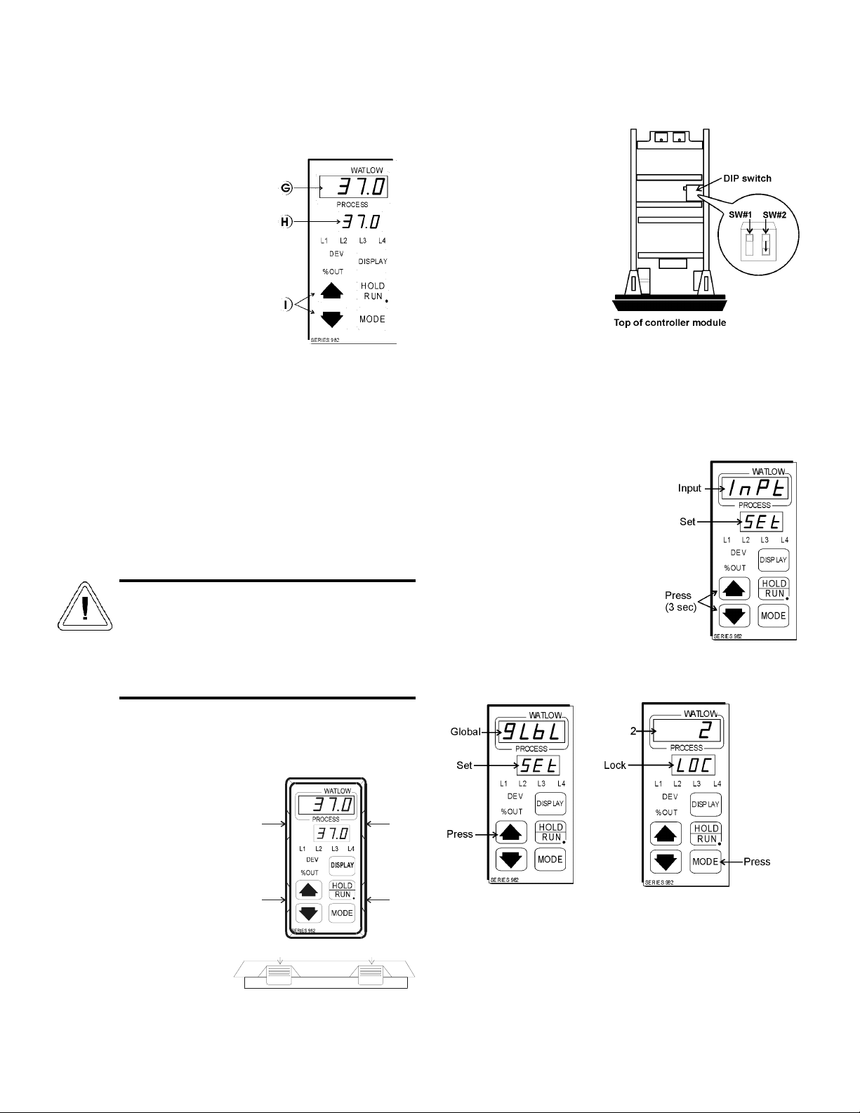
3.2 Setting the Incubator’s Operating Temperature
(Figure 3-3)
The Watlow temperature
controller’s upper numerical
display shows the actual tem-
perature inside the incubator
chamber. The lower display
shows the temperature setpoint.
To raise or lower the set-
point, press the up or down
arrow. Temperatures are set in
0.1°C increments.
3.3 Programming the controller
The Watlow temperature controller has been set at the fac-
tory to operate the incubator within the specifications listed in
Section 6 of this manual. Reference copies of the Watlow con-
figuration records are included at the end of Section 2 of this
manual.
To prevent tampering, mechanical and software lockouts
are employed in the system. These lockouts must only be
removed by persons skilled in configuring controller software.
Making program changes to the temperature con-
troller will seriously alter the performance of the
incubator and therefore must be made only by
qualified persons. The controller should not be
reconfigured without first consulting Thermo
Forma Service Department, at 1-888-213-1790.
a. Removing the mechanical lockout
Make sure the unit is
turned off.
Wearing a grounding wrist
strap or maintaining constant
contact with the metal cabinet,
press in the four locking tabs
on the frame of the
Temperature controller. There
are two tabs on either side as
shown in the front and side
views in Figure 3-4. When all
tabs are unlocked, pull the con-
troller module out of its frame.
Looking at the top of
the module, locate the red
DIP switch indicated in
Figure 3-5. With a finger-
nail or small screwdriver,
turn off SW #2 by moving
the white toggle down or
towards the front of the
module.
Very carefully, replace
the module into its frame
and press firmly on the top
and bottom of the bezel
until all four locking tabs
“click” into place.
b. Removing the Software Lockout
Press the up arrow and down
arrow keys at the same time and hold
them for about three seconds. The
words “inpt” (input) and “set” will
appear in the top and bottom dis-
plays. (Figure 3-6) If numbers in the
bottom display begin to scroll up or
down, the keys have not been
pressed simultaneously. Try again.
Press the up arrow until “gLbL”
(global) appears in the upper display.
The word “set” will remain in the
lower display (Refer to Figure 3-7).
Press the Mode key to scroll through the menus until the
upper and lower displays show “2 Loc” (Figure 3-8).
G
H
I
PressPress
Press
Press Press
Press
Front View
Side View
Figure 3-3
Figure 3-4
Figure 3-5
Figure 3-6
Figure 3-7 Figure 3-8

Model 3920 ___________________________________________________________________Routine Maintenance
4 - 1
Press the down arrow key until the
2 becomes 0 (zero) as shown in Figure
3-9.
Press the Display key to return to
showing the setpoint and actual tem-
peratures. All safeguards are now
removed and the controller may be
programmed. Refer to the Watlow
publications included with this operat-
ing manual.
Reprogramming the temperature or humidity
controllers will change the factory default set-
tings and may seriously alter the performance of
the incubator and void the warranty. Contact the
Thermo Forma Service Department, at 1-888-
213-1790.
3.4 Air Exchange Ventilator Caps
Air exchange for the incubator is regulated through the
manually adjustable intake and exhaust ventilator caps located
on the top of the cabinet.
When viewed from the front of the incubator, the intake
cap is on the left, and the exhaust cap is on the right. The venti-
lator caps may be opened by turning counterclockwise and
closed by turning clockwise.
For optimum performance of the unit, the ventilator caps
should be closed at all times.
Figure 3-9
Section 4 - Routine Maintenance
4.1 Cleaning the Incubator
De-energize all potential
sources of energy to this
unit and lockout/tagout
their controls. (O.S.H.A.
Regulation, Section 1910-
147.)
The continued cleanliness of the stainless steel used in
Forma products has a direct effect on the appearance and opera-
tion of the unit. Use the mildest cleaning procedure that will do
the job effectively. Clean the outside of the incubator with soap
and water or with any non-abrasive commercial spray cleaner.
Clean the inside of the chamber with alcohol and/or soap and
water. Disinfect the interior panels with a general use laboratory
disinfectant, diluted according to the manufacturer’s instruc-
tions. rinse the surface thoroughly after each cleaning and wipe
the surfaces dry. Always rub in the direction of the finish pol-
ish lines.
Do not use chlorinated solvents on stainless steel
as they can cause rusting and pitting.
Do not use volatile or aromatic solvents for
cleaning inside the cabinet as their residue can
contaminate the cabinet environment.
The Thermopane glass door may be cleaned with commer-
cial glass cleaner or with a solution of ammonia and water.

Model 3920__________________________________________________________________________________________________________________Preventive Maintenance
4 - 2
PREVENTIVE MAINTENANCE
Incubators
Your equipment has been thoroughly tested and calibrated before shipment. Regular preventive maintenance is important to keep your unit function-
ing properly. The operator should perform routine cleaning and maintenance on a regular basis. For maximum performance and efficiency, it is rec-
ommended that the unit be checked and calibrated periodically by a qualified service technician.
The following is a condensed list of preventive maintenance requirements. See the specified section of the instruction manual for further details.
Thermo Forma has qualified service technicians, using NIST traceable instruments, available in many areas. For more information on Preventive
Maintenance or Extended Warranties, please contact us at the number below.
Cleaning and calibration adjustment intervals are dependent upon use, environmental conditions and accuracy required.
Tips for all incubators:
• Do NOT use bleach or any disinfectant that has high chloros.
• Use sterile, distilled or demineralized wqater.
• Avoid spraying cleaner on the CO2sensor.
• Do not use powdered gloves for tissue cultures.
•Millcreek Road, Box 649 •Marietta, Ohio 45750 USA •740-373-4763

Model 3920_______________________________________________________________________________________________________________Preventive Maintenance
4 - 3
Preventive Maintenance for Model 3920
Refer to Manual Section Action Daily Weekly Yearly
-- Inspect door latch, hinges and door gasket seal ;
3.4 Check air exchange ventilator caps for adjustment;
open or close as required ;
4.1 Perform a complete decontamination procedure. Wipe down interior, shelves, Between Experiments
side panels with disinfectant. Rinse everything well with sterile distilled water. More frequent decontamination may be
required, depending on use and
environmental conditions.
2.9 * Verify and document all calibrations, at the minimum. ;
-- Clean drip pan and drain lines ;
-- Verify defrost cycle for below 10°C operation ;
-- Change filters (under normal conditions) ;
* Qualified service technicians only
5.3 Replacing the Temperature Sensor
1. Locate the probe mounting plate in the center of the
right side of the incubator interior.
2. Open the mounting plate by removing the screws that
hold it in place.
3. Locate the sensor mounted on the inside of the panel in
a black housing. Note the angle of the probe.
4. Grasp and unplug the probe from the probe cable.
5. When replacing the sensor, be sure to mount the probe at
the same angle as it was originally mounted.
5.4 Removing the Top Section
If it becomes necessary to remove the top of the incubator
for moving it through low doorways, refer to the points follow-
ing, then use the indicated procedure:
• Read the instructions completely before starting the
removal process.
• Provide adequate space and sufficient lighting to perform
the work.
• Disconnect the inlet water supply and the drain.
• Before lifting the top section from the incubator, provide
carpenter’s horses or another suitable support arrangement
so that the underside of the top is suspended.
Procedure:
1. Remove all test material from the incubator chamber.
2. All temperature-sensing probes are mounted on a probe-
mounting bracket on the right side of the incubator
chamber. Remove the nuts securing the bracket and
then remove the probes from the bracket. Note the loca-
tion and configuration of the probes.
3. The sensing bulb capillaries are routed behind the duct
sheet, up to the access port at the top of the unit and
behind the control panel.
Note: Route all the probes between the duct sheet and the out-
side wall of the chamber so that when the top is raised, all
probes will move freely up and out. Do not kink or bend the
capillaries.
4. Open the control panel by removing the two screws
located on the left side of the control panel.
5. Loosen the top gasket around each of the air exhaust
vents by turning the screw.
6. Remove the eight screws from the top cover of the incu-
bator.
7. Remove the four screws from each of the vent caps on
the top cover of the incubator. The top cover can now be
removed.
Section 5 - Service
Servicing must be performed by qualified service
personnel only!
De-energize all potential
sources of energy to this
unit and lockout/tagout
their controls. (O.S.H.A.
Regulation, Section
1910-147.)
5.1 Access to the Electrical Components
To gain access to the electrical components, remove the
two screws located on the left side of the control panel with a
phillips screwdriver. The control panel is hinged and will swing
open.
5.2 Replacing the Overtemp/Undertemp Probe and
Thermostat
1. Remove the incubator ceiling by remove the screws
holding it in place.
2. Remove the top three screws from the top of the right
duct cover.
3. Lean the duct sheet out, and remove the Permagum seal
from around the probe access hole.
4. Remove the 15” copper capillary overtemp probe by
extracting the two plastic clips that hold the probe in
place.
5. Open the control panel by removing the two screws
located on the left side of the control panel.
6. Pull the overtemp probe up through the access hole and
into the control panel.
7. Follow the wires from the probe to the thermostat
mounted on the control panel. Clip the plastic ties hold-
ing the overtemp cable to the existing wiring.
8. Pull the overtemp knob on the control panel off.
9. Remove the two screws that hold the overtemp assembly
to the control panel.
10. Disconnect the two wires from the back of the thermo-
stat assembly.
11. Pull the entire assembly out of the panel, and remove the
unit.
12. Replace the thermostat and probe.
Note: Reseal the probe access hole with Permagum, and retie
the overtemp cable to the existing wires after replacing
the probe.
Model 3920 _______________________________________________________________________________Service
5 - 1

5.5 Setting the Door Heater Control
High voltage is present behind the
control panel. Servicing must be per-
formed only by qualified electrical
service personnel.
The infinite heater control is located in the right side of the
incubator top compartment behind the control panel door. The
heater varies the amount of door heat from no heat (zero) to full
heat (100) as indicated by the control dial face. If the knob is
turned past zero, a “click” will indicate that all power to the
door is shut off. If turned past 100, a similar “click” will indi-
cate that the heat is set at the maximum.
Initially, the units leave the factory with the dial set at 40.
If desired, the amount of heat can later be reduced until mois-
ture appears on the door, then the heat advanced. However, in
fluctuating ambient conditions, it is recommended that 40%
door heat be used.
8. Remove the nine 5/16” x 4” hex head bolts, lock wash-
ers, and two flat washers which secure the top assembly
to the cabinet. Note the washer arrangement on the
bolts.
9. Remove the black trim gasket located at the junction of
the top assembly and the main incubator section. The
ends of the gasket have been joined together at the rear
of the incubator.
Note: When raising the top section, note the orientation of the
gasket seal at the top opening of the incubator chamber. The
gasket must be correctly positioned when reinstalling the top on
the chamber.
10. Slowly lift the entire top assembly up and off the lower
chamber section while carefully guiding the capillaries
and sensing bulbs out of the chamber area. Place the top
assembly onto the carpenter’s horses or other support
arrangement.
11. Reinstall the top assembly by reversing the above proce-
dure. Exercise care particularly when:
• Placing and aligning the sealer gasket on the 1/2” flange
on top of the chamber when lowering the top in place.
• Routing the temperature and/or humidity sensors and
capillaries to prevent severely bending them.
• Mounting the temperature and/or humidity sensor bulbs
on the mounting brackets.
• Tightening the top mounting bolts alternately, to ensure a
balanced pressure on the gasket.
Model 3920 _______________________________________________________________________________Service
5 - 2
Figure 5-1

Section 6 – Specifications
Temperature
Control ±0.3°C @ +25°C to +37°C
Range 0°C (32°F) to +60°C (140°F)
Sensor RTD
Controller Digital electronic proportional
Setpoint Digital
Display Digital LED
Readability 0.1°C
Setability 0.1°C
Uniformity ±0.3°C at 25°C to 37°C with
six shelves installed*
Shelves
Standard 6
Maximum 19
Dimensions 30.62”W x 25.81”F-B
(77.78 cm x 65.56 cm)
Construction Solid stainless steel reinforced
Surface Area 5.4 sq. ft. (.51 sq. m) per shelf
Max. Per Chamber 104.3 sq. ft. (9.69 sq. m)
Clearance Adjustable on 3” (7.62 cm)
centers
Loading 35 lbs. (16 Kg) (slide in and out)
50 lbs. (23 Kg) (stationary)
Construction
Volume 29 cu. ft. (823 liters)
Interior 304 2B stainless steel
Exterior Cold rolled steel
Insulation 2” (5.1cm) Foamed urethane
Outer Door Gasket Four sided vinyl compression
Finish Powder coated. Salt spray tests
exceed 1000 hrs. per ASTM
Standard B117-85.
Weights
Net 700 lbs.
Shipping
Motor 850 lbs.
Temperature Alarm
Sensor Thermostat
Controller Thermostat
Setpoint Analog reference dial
Alarm Audible/visual
Fittings
Drain Port 3/8” OD Copper
Unit Heat Load
115V 5500 BTUH (1600W)
220V 6000 BTUH (1750W)
Refrigeration
Compressor 1/4 Horsepower, air-cooled
R-134A
Electrical
120V, 1 PH, 2W, 60Hz, 16 FLA
Power Switch 1 Pole
Line Cord None (lockable disconnect
provided)
Dimensions
Exterior 38.0”W x 87.5”H x 32.0”F-B
(96.5cm x 222.3cm x 81.3cm)
Interior 31.0”W x 60.0”H x 27.0”F-B
(78.7cm x 152.4cm x 68.6cm)
Continuing research and improvements may result in specification
changes at any time. Performance plus or minus the least significant
digit unless otherwise specified.
* Better than ±0.5°C uniformity at all other temperature parameters.
Model 3920 _________________________________________________________________________Specifications
6 - 1
Table of contents
Other Thermo Forma Laboratory Equipment manuals

Thermo Forma
Thermo Forma 3940 Operating instructions

Thermo Forma
Thermo Forma 923 Operating instructions

Thermo Forma
Thermo Forma 1284 Operating instructions

Thermo Forma
Thermo Forma 1200 Series Operating instructions

Thermo Forma
Thermo Forma 3911 Operating instructions

Thermo Forma
Thermo Forma Cryomed 1010 Operating instructions
Popular Laboratory Equipment manuals by other brands


Mark-10
Mark-10 ESM301 user guide

Sartorius Stedim Biotech
Sartorius Stedim Biotech BIOSTAT CultiBag RM 600 operating manual

Scientifica
Scientifica Multiphoton Scanhead Setup and operation manual

Thermo Electron
Thermo Electron SORVALL RC3BP operating instructions

Sanuvox
Sanuvox ASEPT.2X troubleshooting guide

Lonza
Lonza 4D-Nucleofector quick guide