Bassi FGM User manual

[V.100 – Feb 2012] FGM
User Manual
___________________________________________________________________________________________________________________________________________________
FGM
HIGH FREQUENCY BATTERY CHARGERS
USER'S MANUAL
www.bassi-srl.eu
1. SAFETY PRECAUTIONS
1 Before to start using the FGM Charger, read these instructions carefully.
2 Installation and Service operations can be done by ualified personnel only.
3 To prevent the risk of electric shock, don't touch uninsulated parts of the charger or the battery.
4 Manually stop the charger before to disconnect the battery.
5 The charger is suitable for indoor installation, in ambients with abundant ventilation.
6 Don't use the charger near flammable materials.
7 Don't obstruct the ventilation slots and leave sufficient free space around the unit.
8 Don't expose the charger to li uids, excessive dust or vibration.
9 Check the conditions of cables and accessories on a regular basis, and replace them
immediately if they get damaged.
10 Don't extend the battery cables. Replace them, if necessary, with cables of the same type,
length, section and insulation as the original ones.
11 During the installation of the charger, make sure to connect the EARTH conductor properly, and
respect all the applicable Safety Standards.
12 Don't modify any part of the charger. Any modification, applied without written authorization of
the manufacturer, may generate unsafe operating conditions and will void the warranty
2. DESCRIPTION
The FGM Charger has been designed to charge Lead-acid or GEL motive batteries. This charger converts the
AC input to DC, at the proper value to charge the battery.
The FGM is based on High-Fre uency Switchmode technology, which allows very compact size and efficient
operation. The operation is completely automatic, and it's managed by a microprocessor based control system.
The exclusive charging curve of the FGM charger allows to reduce the charging factor to the minimum value, so
the duration of the overcharge/gassing phase and the average temperature of the battery are minimized.
__________________________________________________________________________________________________________________________________________________
Page 1/3
[V.100 – Feb 2012] FGM
User Manual
___________________________________________________________________________________________________________________________________________________
3. INSTALLATION
Conditions of use:
•Temperature (operation): from 0°C to 40°C.
•Temperature (storage): from –20°C to 60°C.
•Relative Humidity: less than 75 %.
The charger must be connected to the AC input using an ade uate cable, plug and protections.
The charger is suitable for FIXED or ON-BOARD installation. In any case, it is recommended to take all the
necessary precautions in order to ensure sufficient ventilation, and good protection against vibrations.
For ON-BOARD installation, it is recommended to use anti-vibration mounts.
Respect the polarity of the battery (+/-) at the connection. The charger is protected against reverse polarity.
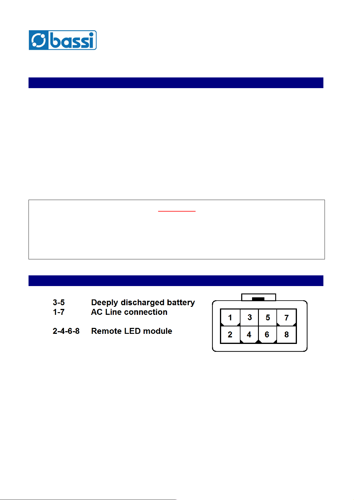
4. AUXILIARY CONTACTS
The charger is e uipped with two Auxiliary contacts, to be connected to the vehicle in on-board installations.
–Deeply dischar ed battery (Terminals #3 and #5)
This contact is NC (normally closed) and it opens if the battery voltage is lower than a programmed
minimum value (default 1.75 V/cell). It is intended to stop or limit the vehicle operation when the battery
is deeply discharged.
–AC input connected (Terminals #1 and #7)
This contact is NC (normally closed) and it opens when the AC line is connected to the charger. It is
intended to prevent the vehicle from moving while the AC input plug is connected.
When the charger is not visible in on-board installations, it is possible to add an optional REMOTE LED
MODULE, to be positioned on the vehicle dashboard. Contact the manufacturer for more details.
__________________________________________________________________________________________________________________________________________________
Page 2/3
ATTENTION !
It's recommended to control that the AC input volta e available at the
installation site has the ri ht value, and that the power available is sufficient.
The nominal AC input volta es that the char er can accept, and maximum input current and power are
reported on the nameplate of the unit.

[V.100 – Feb 2012] FGM
User Manual
___________________________________________________________________________________________________________________________________________________
5. OPERATION
Connect the battery and the AC input. The charge will begin automatically and the LED “In charge” will turn on.
When the charge will be completed, the charger will stop automatically, and the LED “Charge complete” will turn
on.
The charging time depends on the programmed curve, the size of the battery and its initial SOC (state of
charge). In any case, duration of the charge is automatically adjusted by the charger, depending on the real
battery condition.
AC INPUT BLACK OUT
If there is a black-out of the AC input, while the charge is in progress, the charger will shut down, while the
charge parameters will remain in memory.
When the AC input will be recovered the charger will restart the charge cycle automatically.
EQUALIZE-MAINTENANCE
These functions are useful to keep the battery in perfect condition and to extend its life, even when it's not used
for an long period (weeks, months, ...).
It is sufficient to leave the battery connected to the charger. After a normal termination of the charge, it is
sufficient to leave the battery connected for 2 days (typically the weekend). The charger will let the battery cool
down before to execute an automatic e ualization cycle.
If the battery will remain connected for extended periods (weeks or months), the charger will switch automatically
to maintenance mode, by activating automatically refresh-maintenance cycles when needed.
DISCONNECTION OF THE BATTERY DURING THE CHARGE
ARNING !
DON'T DISCONNET THE BATTERY DURING THE CHARGE.
RISK OF EXPLOSION!!!
If it's necessary to disconnect the battery while it's bein char ed, press the STOP pushbutton for two
seconds, in order to stop the char er manually.
The charger will suspend the charge and the LED “Charge complete” will turn on. At this time it's possible to
disconnect the battery.
ERROR SIGNALS
If a faulty condition is detected, the charger will stop automatically and generate a fault signal:
DEFECTIVE OR INCORRECT BATTERY: Both LEDs flashing
CHARGER FAILURE: Both LEDs remain in ON state
www.bassi-srl.eu
- End of Manual -
__________________________________________________________________________________________________________________________________________________
Page 3/3
Table of contents
Other Bassi Batteries Charger manuals


Popular Batteries Charger manuals by other brands

SENSIT Technologies
SENSIT Technologies GAS TRAC LZ30 Operational manual

DIAL ENGINEERING
DIAL ENGINEERING IUPITER Series Instructions for use

ROLEC
ROLEC Sinexcel ULTRACHARGE 160 Installation & operation manual

Optimate
Optimate TM260 Instructions for use

Analytic Systems
Analytic Systems IBC320 Installation & operation manual

Adler
Adler BOOST-18/1 instruction manual


