ROLEC Sinexcel ULTRACHARGE 160 User manual

Stocked in
the UK by
INSTALLATION & OPERATION MANUAL
ULTR ACHARGE 160
Intelligent ultra-rapid EV charging station

Product Support
UltraCharge 160 DC Charger EVUCM-001-V01R1 Installation and Operation Manual
Page 1of 30 October 2023
Amendments
Amendment
Number Details Date
Ver 1, Rev 0 New Document. Jan 2023
Ver 1, Rev 1 Update of wording throughout manual Oct 2023
Product: UltraCharge 160 DC Charger
Models: EVDC2010 – 60kW EVDC2030 – 120kW
EVDC2020 – 80kW EVDC2040 – 160kW
Document Type: Installation and Operation Manual
Document Code: EVUCM-001-V01R1
Language: UK English (Original)
Date Published: October 2023
Rolec Services Ltd are the publishers of this document and own the rights to use the text, images and all technical
content contained within. Content supplied by third parties / partner organisations remains the property of that
organisation and is used by agreement with the supplier.
Rolec Services Ltd exercise care to ensure content is as accurate as possible at the time of publication. However, no
guarantee of accuracy should be inferred.
Rolec Services Ltd, Ralphs Lane, Boston, Lincolnshire PE20 1QU. United Kingdom.
+44 (0) 1205 724754
enquiries@rolecserv.co.uk
Product Support
Updates to this manual will be made available on the Rolec website at
https://www.rolecserv.com/downloads-ev-charging
Check the document date, and the Version and Revision number shown at the
end of the Document Code (V01-R0, V01-R2, V02-R0, etc).
For installation assistance and advice, contact your preferred electrical
installer.

Product Support
EVUCM-001-V01R1 Installation and Operation Manual UltraCharge 160 DC Charger
October 2023 Page 2of 30
Contents
Product Support 1
Safety 3
Safety Advice Within this Manual 3
Disclaimer 4
Equipment Warnings 5
Safety Instructions for Use 6
Safety Instructions for Operation 6
Product Overview 8
Short description 8
Charger Models 8
Product Views 8
Product Characteristics 10
Product Specifications 11
Installation instructions 12
Equipment Dimensions 12
Equipment Installation Requirements 13
Distribution Cables 14
Layout Requirements of Distribution Cables 14
Requirements for Distribution Cables 15
Cable for AC Input (Recommended) 15
Internal Wiring 16
Installation 17
Tools required 17
Unpacking the Outer Package of the Cabinet 17
Foundation Drilling 19
Site the Charger 20
Inspection After Installation 24
Stability 24
Clean Up 24
Inspection 24
Operation Interface 25
Charging Process 25
Standby Interface 25
Code Scanning Charging Interface Process 27
Interface Process of Pay by Card Charging 28
Password charging interface process 29
Simple Troubleshooting 30
After-Sales Service 30
IMPORTANT:
This document is primarily intended for the following engineers:
xTechnical Support Engineer
xMaintenance Engineer
xEngineering installation team

Safety
UltraCharge 160 DC Charger EVUCM-001-V01R1 Installation and Operation Manual
Page 3of 30 October 2023
Safety
This manual is specifically applicable to the UltraCharge 160 DC Charger and is provided
as a guide to its installation.
IMPORTANT: Engineers must read and understand the content of this manual
before installation and/or use of the product.
Engineers must be properly qualified and competent to do work on the equipment in
accordance with the current legislation applicable in the geographical region of the
installation.
xRolec Services Ltd cannot accept any responsibility for improper actions performed
by engineers or end users.
xThe information provided in this manual must ONLY be used with the model(s) listed on
page 1 of this manual.
xThe information provided in this manual must NOT be used with any other product.
xThe content of this manual may be updated by the manufacturer as required.
xDo NOT use the equipment for anything other than its intended purpose.
xDo NOT modify the equipment unless specifically instructed to do so by the
manufacturer.
xDo NOT attempt to repair the equipment unless specifically instructed to do so by the
manufacturer.
xTo maintain electrical safety, the body enclosure of the product (access covers) must
be secured in their correct location using the supplied fasteners and the seal must be
sufficient to maintain the IP rating of the enclosure.
xFasteners used to mount the product in its working location must be sufficient for the
task and the specific mounting point.
xDamage to the product may render it unsafe. The product must be electrically
isolated and NOT used until appropriate remedial action has been performed.
xRolec does NOT recommend the use of charging extension cables or adapters and
their use may invalidate the charge point warranty.
Safety Advice Within this Manual
Rolec manuals use a system of warnings, cautions and notes.
xWARNINGS concern the safety of installers/end user and will be given before the
detail/instructions in the manual.
xCAUTIONS concern the potential for damage to the equipment and will be given
before the detail/instructions in the manual.
xNOTES are given to provide additional information and/or to highlight information of
importance. They will be given either before or after the detail/instructions as
appropriate and may use different wording (such as IMPORTANT) where emphasis is
required.
Warnings, Cautions and Notes may be repeated several times as appropriate and may
be preceded by a hazard symbol where appropriate.

Disclaimer
EVUCM-001-V01R1 Installation and Operation Manual UltraCharge 160 DC Charger
October 2023 Page 4of 30
Disclaimer
Rolec shall not be liable for personal injury, product damage, failure or defects in
scenarios such as but not limited to:
xInstallation and/or maintenance performed by unlicensed/unqualified personnel.
xLack of appropriate maintenance in accordance with the maintenance manual.
xLack of appropriate maintenance in accordance with local specifications and
standards.
xFailure to adequately record maintenance activities.
xUnauthorised changes to the design and/or functionality of the product.
xProduct damage or failure caused intentionally or by negligence.
xProduct damage or failure caused by improper/negligent actions performed by
Installation and/or maintenance personnel.
xProduct damage or failure caused by ‘force majeure’ (such as a bad weather,
natural disasters, etc.).
xMaintenance personnel not wearing appropriate protective equipment.
xThe failure (when requested) to return failed components to the
manufacturer/supplier for analysis.
WARNING: Personal Injury and Equipment Damage
xBefore maintenance, make sure the power supply to the charger has been
switched OFF.
xMake sure any faults have been eliminated and the electric circuit has been
connected properly before initiating a power on test.
xPersonnel who maintain the equipment, including operators, trained personnel
and professional must, where required, possess the local national qualifications to
work with high-voltages, work at heights, and to work in operations of special
equipment.

Equipment Warnings
UltraCharge 160 DC Charger EVUCM-001-V01R1 Installation and Operation Manual
Page 5of 30 October 2023
Equipment Warnings
Symbol Meaning Description
DANGER Parts of the system are at High Power during operation.
Direct or indirect contact with these components can be
fatal.
DANGER
High voltage area may cause fire or electric shock.
The construction of the area and conduits for cables must
comply with national legislation.
Only staff authorised to work with high AC and DC voltages
can work in these areas.
DANGER It is forbidden to do maintenance work in bad weather.
DANGER It is forbidden to do maintenance work when the
equipment is live.
WARNING Special tools must be used when working with high AC and
DC voltages.
WARNING Wear the appropriate personal protective equipment (PPE).
CAUTION Read and understand the manual.
CAUTION Protective equipment and tools must be used.
Make sure all protective items are removed from the
equipment before applying power.
CAUTION Always follow national legislation.
xThis product is high-power and high-voltage equipment. Construction and
maintenance personnel must have the appropriate certification for their region to
work with the equipment.
xAll personnel must abide by the construction standards and safety regulations
applicable in their region.
xThe equipment has been developed, manufactured, checked and certified in
accordance with the relevant safety standards. Therefore, if the instructions for the
specified use and technical instructions for safety are followed, under normal
circumstances the product will not cause property damage or endanger human
health.
xThe instructions contained in this manual must be strictly observed or safety may be
compromised. Although this manual explains the relevant safety instructions,
personnel must be aware of the type of hazards associated with their work and must
take the appropriate precautions to prevent accidents and injury.
xIn the event of problems and/or failures in the use of the equipment, the user shall
directly consult the supplier/manufacturer.
xAny work performed by third parties without the approval of the
supplier/manufacturer is done at their own risk to health and to the serviceability of
the equipment. The supplier/manufacturer cannot be held responsible.

Safety Instructions for Use
EVUCM-001-V01R1 Installation and Operation Manual UltraCharge 160 DC Charger
October 2023 Page 6of 30
xMaintenance periods and tasks must be observed.
xA comprehensive record of maintenance must be available to support warranty
claims.
xMaintenance personnel must use the appropriate protective equipment/clothing
when engaging in work.
xAll electrical power to the charge point must be OFF before engaging in any work.
xEven when all the switches of the charger have been disconnected, the copper bar
of the charging line may still hold a dangerous voltage. During maintenance:
xTurn off the upper switch of the charger.
xDisplay a warning sign that maintenance is in progress.
xCheck whether there is a dangerous voltage with an instrument to ensure
that the charger is completely disconnected from the power grid.
xIt is strictly forbidden to do the maintenance work in a bad weather such as
thunderstorms.
xIt is strictly forbidden to do the power-on test before troubleshooting.
xAfter work, all doors, panels, etc must be securely closed.
Safety Instructions for Use
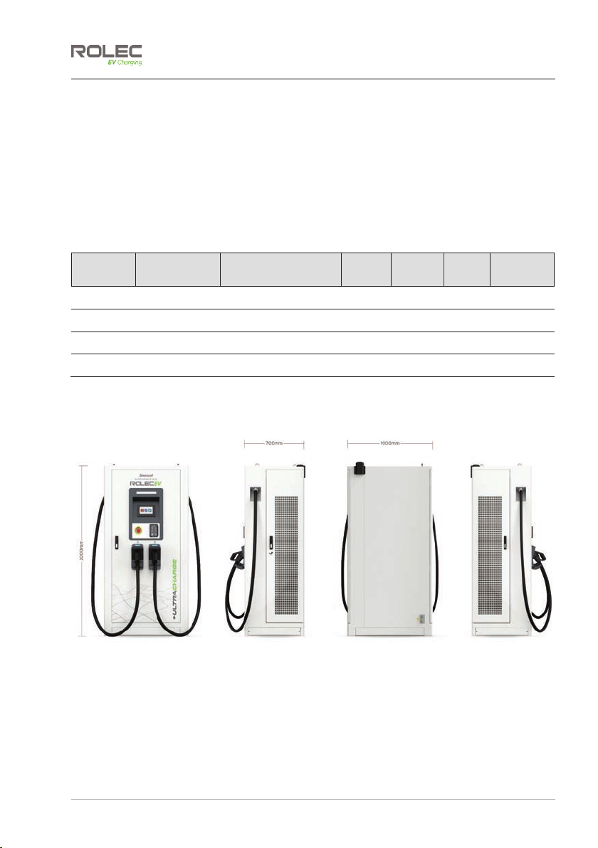
xThe UltraCharge 160 is an integrated charger to supply electricity to an EV either
outdoor or indoor.
xThe UltraCharge 160 is a high-power and high voltage electric power equipment.
Installation and maintenance must only be done by appropriately qualified
professionals.
xFollow local laws and regulations when installing, operating, or maintaining the
equipment.
xFollow the procedures of installation, operation, and maintenance and make sure this
document and accessories are available.
xPay attention to the safety symbols on the equipment and all the safety instructions in
this document.
xWhen operating equipment has encountered any problems or faults, please contact
Rolec Technical Support directly.
xUnauthorized third-party maintenance will invalidate the warranty,
xMakes sure the unit is not installed near to potentially dangerous equipment or other
hazards.
xMake sure that the space around the equipment cannot be blocked.
Safety Instructions for Operation
xBefore using for the first time, you must read this document carefully. Make sure the
equipment is installed and commissioned according to the instructions in the
installation manual.
xDo not perform unauthorized modifications to the product. The manufacturer will not
be liable for any consequence caused by the violation of the safety operation
regulations and design, production, and usage standards.
xDo not touch the EV charging connector or vehicle inlet, keep it dry and clean.

Safety Instructions for Operation
UltraCharge 160 DC Charger EVUCM-001-V01R1 Installation and Operation Manual
Page 7of 30 October 2023
xDo not use this product if the power cord or connector shows any signs of damage.
xIn case of any abnormal operation or conditions, press the emergency button
immediately to turn off all electrical input and output.
xIf the emergency button is pressed, the system operator should be informed. The
charging station must not be restarted until the system operation technician resets the
system.
xMake sure there is no debris or fluids in the EV charging connector or vehicle inlet.
xDo not attempt to connect or disconnect power cables when power is on.
xWhen performing maintenance, turn off the power switch, ensure that electrical
connections are correct, and display warning notices in the area.
xPay attention to the copper wire carries dangerous voltage of equipment, even when
all circuit breakers of the charger are disconnected.
xConnect protective earth wire (PE) before connecting neutral line and phase line.
xAfter installation or maintenance, make sure that all doors are correctly secured.
xAdaptors or conversion adapters are not allowed be used.
xExtension cords are not allowed be used.

Product Overview
EVUCM-001-V01R1 Installation and Operation Manual UltraCharge 160 DC Charger
October 2023 Page 8of 30
Product Overview
Short description
The UltraCharge 160 is an integrated DC fast charger that features high efficiency and
flexible configuration. It supports the charging of two vehicles at the same time at same
time and meets the charging demand of larger capacity and high endurance electric
vehicles.
Charger Models
Station
Level Connection
Type Power Allocation Input
Current Input
Power Unit
Colour Product
Code
60kW DC 1x CCS2
1x CHAdeMO 1x 60kW
1x 40kW / 1x20kW* 112A 67kVA White EVDC2010
80kW DC 2x CCS2 1x 80kW
2x 40kW* 150A 89kVA White EVDC2020
120kW DC 2x CCS2 1x 120kW
2x 60kW* 224A 133kVA White EVDC2030
160kW DC 2x CCS2 1x 160kW
2x 80kW* 299A 177kVA White EVDC2040
*When 2 vehicles are charging simultaneously
Product Views
Figure 1 External View

Product Overview
UltraCharge 160 DC Charger EVUCM-001-V01R1 Installation and Operation Manual
Page 9of 30 October 2023
Figure 2 External Components
AEye Bolts for Lifting
BStatus LED
CScreen
DEmergency Button
EDoor Handle/Lock
FCharging Connector
GAntenna
HPayment Card Reader
IAir Outlet
Figure 3 Internal Components
AMain Circuit Breaker
BAC Incoming Copper Bar
CInlet Hole
DGrounding Bar

Product Characteristics
EVUCM-001-V01R1 Installation and Operation Manual UltraCharge 160 DC Charger
October 2023 Page 10 of 30
Product Characteristics
xA variety of power configurations from 60kW to 160kW.
xFlexible power distribution – the dual connector model can automatically switch the
power according to the vehicle demand, and the rapid charging of two vehicles at
the same time.
xThe constant current and constant power charging methods have the advantages of
high charging efficiency, simple operation and reliable performance.
xUltra-wide output voltage range, the highest output voltage can reach DC1000V. It
can not only meet the low-voltage charging of small cars, but also meet the charging
requirements of buses and high-voltage vehicles.
xWith overload, short circuit, leakage, lightning protection, overcharge, over voltage,
under voltage, reverse connection, over temperature and other multiple protection
functions.
xThe intelligent standby mode can effectively reduce the operation cost of customers
in the whole project life cycle and improve the return rate of station charging.
xThe cabinet shell is made of stainless steel with protection grade of IP55, which can be
applied to various outdoor environments.

Product Characteristics
UltraCharge 160 DC Charger EVUCM-001-V01R1 Installation and Operation Manual
Page 11 of 30 October 2023
Product Specifications
Category Item Parameter
Input Characteristic
Input 3P+N+PE
Input Voltage AC 380~400V
Frequency 50/60Hz
Power Factor 0.99
THDi <5%
Output Characteristic
Output Voltage CCS2 : 200-1000 Vdc
CHAdeMO: 200-500Vdc
Rated power 60-160kW
Max Current CCS2 : 200A
CHAdeMO: 125A & 200A
Peak Efficiency 95% @half load
Connector Type IEC 62196
Standards System
Standards IEC 61851
Others
Energy meter High precision meter
Number of
connectors
1 (CCS Combo 2) or 2 (CCS combo 2,
CHAdeMO optional – Two connectors
can be used at the same time)
Network
Interface LAN
Size W1000 x D700 x H2000 mm
Protection level IP55/IK10
Gross Weight 535KG
Net Weight 460KG
Cable length 5mExposed cable length is 4.5m
Communication
protocol OCPP1.6J/2.0(Upgrade)
Display Screen 7 inch
Method of
payment QR Code/RFID/Mobile phone
(Optional)
Language English
Environmental conditions
Cooling method Forced air cooling
Operating
temperature -25 ~ 65 Ԩ(Derating operation over 45
Ԩ)
Humidity 5%~95%
Altitude P
Protection
Undervoltage & overvoltage protection
DC overcurrent protection
Over temperature protection
Surge protection device
Emergency stop button
Optional tilt, flood and smoke detection
Advanced dynamic power balancing
Supports static load management
(software configurable)

Installation instructions
EVUCM-001-V01R1 Installation and Operation Manual UltraCharge 160 DC Charger
October 2023 Page 12 of 30
Installation instructions
Equipment Dimensions
Figure 4 Outline and Dimension of Charger
Figure 5 Hole Size of Charger Base

Installation instructions
UltraCharge 160 DC Charger EVUCM-001-V01R1 Installation and Operation Manual
Page 13 of 30 October 2023
Equipment Installation Requirements
1. The charger can be opened at the front, left and right-hand sides and charging
connectors can used from both sides.
2. Space should be reserved around. See Figure 8.
3. Installation should be onto a foundation of channel steel or concrete.
xThe cable shall be embedded in advance
xThe reserved length of Ethernet cable should not be less than 4000mm.
xThe reserved length of control signal cable should not be less than 1500mm.
xThe reserved length of power cable reserved shall be 700 mm ± 20 mm, and
the protruding from the base through which 5 wires pass, shall be less than 30
mm, as shown in Figure 9.
4. The height of the installation foundation is recommended to be 200 mm ± 20 mm,
and the vertical inclination of the installation shall not exceed 5°. See Figure 9.
5. Install 4 stainless steel M12 * 80mm expansion bolts between the base and the
cabinet. Note that the bolts need to be equipped with M12 stainless steel flat
gasket.
Figure 6 Requirements for Charger Placement

Installation instructions
EVUCM-001-V01R1 Installation and Operation Manual UltraCharge 160 DC Charger
October 2023 Page 14 of 30
Figure 7 Base and Cable Reservation Requirements
Distribution Cables
Layout Requirements of Distribution Cables
1. The incoming cable(s) should be laid through a cable trench and should enter
charge point enclosure through the inlet hole at the bottom of the charger.
2. The outdoor power cable shall be laid according to the power specification.
xThe AC cable must be sufficiently rated for load of the charger.
xThe power cable and the signal cable must be separated.
xThe signal cable should be put through the tube separately to avoid the loss
and interference of the communication signal.
3. The cable must NOT be laid in an area where damage can be easily sustained due
to mechanical factors, corrosive materials, humidity, strong magnetic fields and
electrostatic field interference. If necessary, apply appropriate protection or
shielding measures.
4. The AC input cable starts from the user's distribution switch and connects to the
copper bar of the charger's inlet cable switch. Protection devices shall be provided
at the user's power distribution.
5. The colour of AC input cable is brown (L1), black (L2), grey (L3), blue (n), yellow
green (PE).
xIf the input cable has only one colour, cable number identification
lables/markers must be applied.

Installation instructions
UltraCharge 160 DC Charger EVUCM-001-V01R1 Installation and Operation Manual
Page 15 of 30 October 2023
Requirements for Distribution Cables
1. Cable laying shall be free from external force, distortion and damage of the
insulation layer.
2. Do NOT twist, flatten, break or abrade the protective layer.
3. The protective pipe must be cleaned before the cable passes through and the wire
must not be damaged.
4. The cable arrangement shall be tidy. The binding should be neat and should not be
crossed.
5. Sufficient allowance must be allowed for each wire of the cable, and the bending
degree shall be consistent.
6. Crimp the terminal of the cable head.
7. When crimping the lug of the inlet cable…
xthe heat shrinkable tube should be set between the cable and the lug,
xthe inside and outside of the tube should be smooth without damage and
cracking.
xBefore setting the heat shrinkable tube, make sure all debris is removed from
the cable such as burrs and iron filings.
8. The colour of the tube shall be in accordance with the phase sequence.
xWhen the tube is heat shrinkable, do not allow excessive heat/flame to enter
the inside of the cabinet as the tube is shrinking.
xThe finished appearance of heat shrinkable tubing should be flat, smooth,
uniform with no holes or cracks.
9. Take care to correctly arrange the wiring sequence if crimping an RJ45 connector
Ethernet cable.
Cable for AC Input (Recommended)
Capacity (kW) Capacity of superior
distribution switch Screw specification
(diameter: mm) Cable terminal
60kW 160A
L1/L2/L3/ N/PE㸸M8 L1/L2/L3/N/PE:
DT35-8
80kW 200A
L1/L2/L3/ N/PE㸸M8 L1/L2/L3/N/PE:
DT50-8
120kW 315A
L1/L2/L3/ N/PE㸸M12 L1/L2/L3/N/PE:
DT120-12
160kW 400A
L1/L2/L3/ N/PE㸸M12 L1/L2/L3/N/PE:
DT150-12

Installation instructions
EVUCM-001-V01R1 Installation and Operation Manual UltraCharge 160 DC Charger
October 2023 Page 16 of 30
Internal Wiring
The internal input cables are N, L1, L2, L3, PE, Ctrl and Eth from left to right.
The ‘Ctrl’ indicates a control signal cable and the ‘Eth’ indicates a ethernet cable.
The cabinet grounding is divided into two parts,
xGrounding bar inside the cabinet
xGrounding of cabinet shell.
Figure 8 Internal Wiring

Installation instructions
UltraCharge 160 DC Charger EVUCM-001-V01R1 Installation and Operation Manual
Page 17 of 30 October 2023
Installation
Tools required
xClaw hammer
xCross screwdriver
xStep ladder
xElectric drill
x(TXLSSHGZLWKǗPPGULOOELW
xInsulating gloves
xCable clipper
xInsulation shoes
xHydraulic clamp
xAdjustable wrench
xSecurity Hex wrench
xCraft knife
Unpacking the Outer Package of the Cabinet
1. Straighten the metal tabs on the top of the packing material and remove the
upper panel.
Figure 9 Unpacking 1
2. Straighten all metal tabs then remove the surrounding panels,

Installation instructions
EVUCM-001-V01R1 Installation and Operation Manual UltraCharge 160 DC Charger
October 2023 Page 18 of 30
3. Carefully cut the plastic bags
wrapped around the cabinet and
remove the PE bags and foam
Figure 10 Unpacking 2
4. Remove the four M12 bolts around
the base
Figure 11 Unpacking 3

Installation instructions
UltraCharge 160 DC Charger EVUCM-001-V01R1 Installation and Operation Manual
Page 19 of 30 October 2023
Foundation Drilling
xThe hole size is shown below:
Figure 12 Foundation Preparation 1
1. Drill four mounting holes with a diameter of 16 mm and a depth of 80-85 mm on the
cement mounting base.
2. Knock four M12 * 80 expansion bolts into the holes.
Figure 13 Foundation Preparation 2
Other manuals for Sinexcel ULTRACHARGE 160
1
Table of contents
Other ROLEC Batteries Charger manuals

ROLEC
ROLEC EV SecuriCharge Series User manual

ROLEC
ROLEC EV Series User manual

ROLEC
ROLEC BasicCharge ROLEC0211B User manual

ROLEC
ROLEC Sinexcel ULTRACHARGE 160 User manual

ROLEC
ROLEC WALLPOD ROLEC4020G User manual

ROLEC
ROLEC SecuriCharge ROLEC0111B User manual

ROLEC
ROLEC OCPP0410 User manual

ROLEC
ROLEC SECURICHARGE ROLEC0111 User manual

ROLEC
ROLEC ZURA ROLEC3020B User manual