Bassi EAGLETRONIC MTL2 Series User manual

SR2400 – SR4803 - SR6000
User's Manual
___________________________________________________________________________________________________________________________________________________
EAGLETRONIC MTL2
SR2400, SR4803, SR6000
USER'S MANUAL
V2.1 – May 2006
.eagletronicchargers.com
__________________________________________________________________________________________________________________________________________________
Page 1/18

SR2400 – SR4803 - SR6000
User's Manual
___________________________________________________________________________________________________________________________________________________
INDEX
· 1. SAFETY INSTRUCTIONS AND WARNINGS............................................. 3
· GENERAL.................................................................................................................... 3
· SHOCK PREVENTION................................................................................................ 3
· BURN AND BODILY INJURY PREVENTION..............................................................
· FIRE AND EXPLOSION PREVENTION......................................................................
· ARCING AND BURNING OF CONNECTOR...............................................................
· MEDICAL AND FIRST AID TREATMENT...................................................................
· 2. DESCRIPTION OF THE CHARGER........................................................... 5
· 3. INSTALLATION OF THE CHARGER..........................................................6
· AC INPUT CONNECTION........................................................................................... 7
· AC INPUT VOLTAGE SELECTION 208/2 0/ 80VAC (ONLY FOR SR 803)............. 7
· AC INPUT VOLTAGE SETTINGS............................................................................... 8
· 4. HOW TO USE THE CHARGER................................................................. 10
· PROGRAMMATION OF THE GASSING POINT....................................................... 10
· BATTERY CONNECTION – VOLTAGE CHECK AND AUTOSTART........................ 12
· CHARGE OPERATION.............................................................................................. 13
· SAFETY TIMER – EMERGENCY STOP................................................................... 1
· AUTOMATIC DATA SAVING..................................................................................... 1
· BLOWN FUSE DETECTION...................................................................................... 15
· AUTOMATIC CHARGE TERMINATION.................................................................... 15
· AUTOMATIC SHUTDOWN ON BATTERY DISCONNECTION................................. 15
· EQUALIZE & REFRESH MODES.............................................................................. 16
· MANUAL CHARGE TERMINATION.......................................................................... 18
· SCHEMATICS & TABLES.............................................................................18
__________________________________________________________________________________________________________________________________________________
Page 2/18

SR2400 – SR4803 - SR6000
User's Manual
___________________________________________________________________________________________________________________________________________________
1. SAFETY INSTRUCTIONS AND WARNINGS
Before to start using your EAGLETRONIC MTL2 battery charger, please take the time to read
these instructions carefully.
The o ner’s manual is an important part of the charger. It’s recommended to keep it in good
condition for the lifetime of the charger. It should be kept in a dry and clean place, al ays
available to the users.
To indicate important instructions, the follo ing blocks are used throughout this manual.
GENERAL
Battery charging products can cause serious injury or death, or damage to other equipment or
property, if the operator does not strictly observe all safety rules and take precautionary
actions.
Safe practices must be learned through study and training before using this equipment.
Only qualified personnel should install, use, or service this equipment.
SHOCK PREVENTION
Bare conductors, or terminals in the output circuit, or ungrounded, electrically-live
equipments can fatally shock a person. To protect against shock, have competent electrician
verify that the equipment is adequately grounded and learn hat terminals and parts are
electrically HOT.
The body’s electrical resistance is decreased hen et, permitting dangerous current to flo
through the body. Do not ork in damp area ithout being extremely careful. Stand on dry
rubber mat or dry ood and use insulating gloves hen dampness or s eat cannot be
avoided. Keep clothing dry.
INSTALLATION AND GROUNDING - A po er disconnect s itch must be located at the
equipment. Check the data label for voltage and phase requirements. If only 3-phase po er is
available, connect single-phase equipment to ONLY TWO WIRES of the 3-phase line.
DO NOT CONNECT the equipment grounding conductor to the third live ire of the 3-phase
line as this makes the equipment frame electrically HOT, hich can cause a fatal shock.
If a grounding conductor is part of the po er supply cable, be sure to connect it to a properly
grounded s itch box or building ground. If not part of the supply cable, use a separate
grounding conductor. Don’t remove a ground prong from any plug. Use correct mating
receptacles. Check ground for electrical continuity before using equipment. The grounding
conductor must be of a size equal to or larger than the size of the line conductors.
CHARGING LEADS – Inspect leads often for damage to the insulation. Replace or repair
cracked or orn leads immediately. Use leads having sufficient capacity to carry the operating
current ithout overheating.
BATTERY TERMINALS – Do not touch battery terminals hile equipment is operating.
__________________________________________________________________________________________________________________________________________________
Page 3/18
CAUTION!
This operation can be dangerous for the user.
ATTENTION!
This operation is important for the functionality and reliability of the charger.

SR2400 – SR4803 - SR6000
User's Manual
___________________________________________________________________________________________________________________________________________________
SERVICE AND MAINTENANCE – Shut OFF all po er at the disconnect s itch or line breaker
BEFORE inspecting, adjusting, or servicing the equipment. Lock s itch OPEN (or remove line
fuses) so that the po er cannot be turned ON accidentally.
Disconnect po er to equipment if it is to be left unattended or out of service. Disconnect
battery from charger. Keep inside parts clean and dry. Dirt and/or moisture can cause
insulation failure. This failure can result in high voltage at the charger output.
BURN AND BODILY INJURY PREVENTION
The battery produces very high currents hen short circuited, and ill burn the skin severely
if in contact ith any metal conductor that is carrying this current.
Do not permit rings on fingers to come in contact ith battery terminals or the cell connectors
on top of the battery. Battery acid is very corrosive. Al ais ear correct eye and body
protection hen near batteries.
FIRE AND EXPLOSION PREVENTION
When batteries are being recharged, they generate hydrogen gas that is explosive in certain
concentrations in air (the flammability or explosive limits are 4.1% to 72% hydrogen in air). The
spark-retarding vents help slo the rate of release of hydrogen, but the escaping hydrogen
may form an explosive atmosphere around the battery if ventilation is poor.
The ventilation system should be designed to provide an adequate amount of fresh air for the
number of batteries being charged. This is essential to prevent an explosion.
Al ays keep sparks, flames, burning cigarettes, and other sources of ignition a ay from the
battery recharging area. Do not break "live" circuits at the terminals of batteries. Do not lay
tools or anything that is metallic on top of any battery.
ARCING AND BURNING OF CONNECTOR
To prevent arcing and burning of the connector contacts, be sure the charger is OFF before
connecting or disconnecting the battery. The ammeter should NOT indicate current flo .
MEDICAL AND FIRST AID TREATMENT
First aid facilities and a qualified first aid person should be available for each shift for
immediate treatment of electrical shock victims.
EMERGENCY FIRST AID: Call phisician and ambulance immediately and use First Aid
techniques recommended by the American Red Cross.
DANGER: ELECTRICAL SHOCK CAN BE FATAL.
If person is unconscious and electric shock is suspected, do not touch person if he or she is
in contact ith charging equipment, battery, charging leads, or other live electrical parts.
Disconnect po er at all s itch and then use First Aid.
Dry ood, ooden broom, and other insulating material can be used to move cables, if
necessary, a ay from person.
IF BREATHING IS DIFFICULT, give oxygen.
IF NOT BREATHING, BEGIN ARTIFICIAL BREATHING, such as mouth-to-mouth.
IF PULSE IS ABSENT, BEGIN ARTIFICIAL CIRCULATION, such as external heart massage.
In case of acid in the eyes, flush very ell ith clean ater and obtain professional medical
attention immediately.
__________________________________________________________________________________________________________________________________________________
Page /18

SR2400 – SR4803 - SR6000
User's Manual
___________________________________________________________________________________________________________________________________________________
2. DESCRIPTION OF THE CHARGER
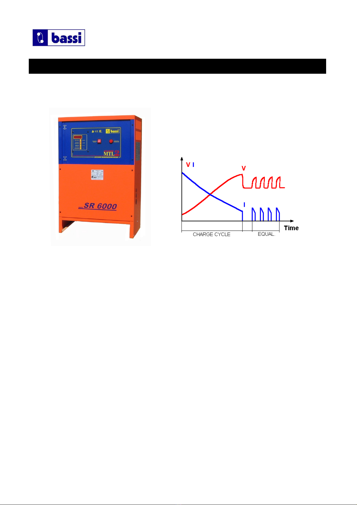
EAGLETRONIC MTL2 battery chargers have been designed to charge Lead-Acid batteries.
These units convert the AC input to a DC output at the correct voltage. The charge curve is of
the type Wa.
The operation of the EAGLETRONIC MTL2 chargers is managed by the ne MTL2 Digital
Charge Controller, hich is a microprocessor based electronic board of the last generation.
Important features of the MTL2 Digital charge controller are:
–Easy Programmation by DIP s itches.
–Programmable Gassing Voltage.
–Proportional Algorithm for charge time calculation.
–Programmable Equalize System (Automatic Pulsed & Manual).
–Automatic voltage-controlled maintenance.
–Wrong battery detection.
–Battery desulphation cycle.
–Independent safety timer.
–Automatic data-saving in case of black out of the mains.
–Cyclical indication of V/cell, AMPS, Ah returned, time.
–Cool do n time counter.
–Scrolling messages in plain text.
The MTL2 Charge Controller monitors the entire charging curve, and it incorporates several
safety features.
The front panel of the MTL2 Digital charge controller contains the digital display (4-Digits), the
STOP button and the MANUAL-EQUALIZE button.
__________________________________________________________________________________________________________________________________________________
Page 5/18

SR2400 – SR4803 - SR6000
User's Manual
___________________________________________________________________________________________________________________________________________________
3. INSTALLATION OF THE CHARGER
Conditions of use:
•Operating temperature: 5°C to 45°C
•Storage temperature: -20°C to 60°C
•Relative humidity: less than 75%
•
__________________________________________________________________________________________________________________________________________________
Page 6/18
CAUTION!
Ris of electrical shoc !
The charger can be installed by qualified personnel only.
To prevent fire or shoc hazard, do not expose the unit to rain or moisture.
Don't use the unit in presence of flammable gas, because it can generate spar s.
ATTENTION!
Ma e sure that the unit's maximum input power (reported on the data label) is available from
your power supply, and verify that the unit's operating voltage is correct.
Allow adequate air circulation to prevent internal heat buildup.
Don't place the unit near heat sources such as radiators or air ducts, or in a place subject to
direct sunlight, excessive dust, mechanical vibration or shoc .

SR2400 – SR4803 - SR6000
User's Manual
___________________________________________________________________________________________________________________________________________________
AC INPUT CONNECTION
The charger must be connected to the AC input using an adequate cable and plug, ith
disconnect s itch and fuses.
The AC input ires have to be connected to the TERMINAL BLOCKS FOR AC INPUT WIRES,
that are located on the right side of the internal panel, just under the AC input contactor.
Make sure to tighten the terminal block scre s ith the proper torque, and pull each ire
separately in order to verify that they are mounted properly.
AC INPUT VOLTAGE SELECTION 208/240/480VAC (ONLY FOR SR4803
The model SR4803 can be configured for 208/240 VAC or 480 VAC nominal input voltage.
This selection can be made ith the 220-240 / 480 VAC SELECTION BOARD, that is located at
the center of the internal panel, near the terminal blocks for the AC input ires.
•Disconnect the charger from main supply and battery.
•Remove the plastic protection over the 220-240 / 480 VAC SELECTION BOARD.
•Remove the three metal bars.
•Place the metal bars in the required position, ith ref to the follo ing pictures.
•Tighten the nuts ith the proper torque.
•Apply the plastic protection.
•Connect the charger to main supply.
SELECTION BOARD
IN POSITION
208-240 VAC
SELECTION BOARD
IN POSITION
480 VAC
__________________________________________________________________________________________________________________________________________________
Page 7/18

SR2400 – SR4803 - SR6000
User's Manual
___________________________________________________________________________________________________________________________________________________
AC INPUT VOLTAGE SETTINGS
•The POWER TRANSFORMER TAPS and the label ith the list of the 5 NOMINAL
voltages that are available, are located on the left side of the internal panel.
SR2400 SR4800 SR6000
1 1x 250 VAC 3x 250 VAC --- 3x 500 VAC 3x 620 VAC
2 1x 2 0 VAC 3x 2 0 VAC --- 3x 90 VAC 3x 610 VAC
3 1x 22 VAC 3x 22 VAC --- 3x 80 VAC 3x 600 VAC
1x 208 VAC 3x 208 VAC --- 3x 60 VAC 3x 575 VAC
5 1x 200 VAC 3x 200 VAC --- 3x 0 VAC 3x 550 VAC
•Using an adequate AC-voltmeter, measure the value of the REAL AC input voltage
available at the mounting location of the charger.
•Identify hich of the 5 NOMINAL voltage values is closest to the REAL measured value.
Example 1: for a charger SR2400 (singlephase) if the measured voltage is 212 V C,
the transformer should be connected to the tap number 4, that
corresponds to 208 V C.
Example 2: for a charger SR6000 (threephase) if the measured voltage is 608 V C,
the transformer should be connected to the tap number 2, that
corresponds to 610 V C
•For the singlephase units (SR2400), the ires to be moved are the TWO that are
connected to the AC contactor, marked ith the letter “A”.
•For the threephase units (SR4803 – SR6000), the ires to be moved are the THREE that
are connected to the AC contactors, marked ith the letters “A”, “B” and “C”.
__________________________________________________________________________________________________________________________________________________
Page 8/18
ATTENTION!
The proper setting of the power transformer taps is fundamental
for the correct operation of the EAGLETRONIC MTL2 chargers.
If the real AC input voltage is different than the AC nominal voltage to which the charger is set,
the charging current of the charger may be significantly different than the nominal.

SR2400 – SR4803 - SR6000
User's Manual
___________________________________________________________________________________________________________________________________________________
Singlephase units (SR2400
Threephase units (SR4803 & SR6000
__________________________________________________________________________________________________________________________________________________
Page 9/18

SR2400 – SR4803 - SR6000
User's Manual
___________________________________________________________________________________________________________________________________________________
4. HOW TO USE THE CHARGER
PROGRAMMATION OF THE GASSING POINT
The possibility to program the gassing point may help the user to adjust the charging curve to
the requirements of the battery during all its life. The default value is 2.40 Volt/cell.
This value can be modified by moving t o dips itches that are located on the MTL board, near
the microprocessor and the black heatsink (see next picture).
The dips itch unit has 4 s itches: the t o central s itches (number 2 and number 3) are used
for the programmation of the gassing point.
To modify the value, follo these steps:
•Disconnect the charger from main supply and battery.
•Locate the dips itches on the digital electronic board (see next picture).
•Set the dips itches according ith the follo ing table and pictures.
•Connect the charger to main supply.
__________________________________________________________________________________________________________________________________________________
Page 10/18
ATTENTION!
The proper programmation of the gassing point is important
for the correct operation of the EAGLETRONIC MTL2 chargers.
Only expert users should modify these settings.

SR2400 – SR4803 - SR6000
User's Manual
___________________________________________________________________________________________________________________________________________________
__________________________________________________________________________________________________________________________________________________
Page 11/18

SR2400 – SR4803 - SR6000
User's Manual
___________________________________________________________________________________________________________________________________________________
DS #2 DS #3 GASSING
POINT
0 0 2.35 V/cell
0 1 2. 0 V/cell
1 0 2. 5 V/cell
1 1 2.50 V/cell
When a battery ill be connected to the charger, the programmed gassing voltage ill be
sho n on the display during the startup sequence.
BATTERY CONNECTION – VOLTAGE CHECK AND AUTOSTART
Connect the battery to the charger, using an adequate plug.
When the battery is correctly connected, the display turns on and sho s the battery voltage.
If the battery voltage lo er than the minimum threshold of 1,62 V/cell, the charger doesn't
start, and the display ill sho the error message “Voltage Lo ”:
If the battery voltage is higher than the maximum threshold of 2,60 V/cell, the charger doesn't
start, and the display ill sho the (flashing) error message “Voltage High”:
If the voltage of the battery is bet een the minimum and maximum thresholds, the charger ill
ait for 3 seconds before to start charging, hile the display ill sho the programmed
gassing voltage.
If, during the charge, the voltage of the battery exceeds the maximum threshold of 2,80 V/cell,
the charger shuts do n automatically, and the errore message “Voltage High” ill appear on
the display.
__________________________________________________________________________________________________________________________________________________
Page 12/18
ATTENTION!
Eagletronic MTL2 chargers are programmed to execute a complete cycle of charge
automatically, however it’s recommended to survey the operations when the battery remains
connected to the charger for more than 12 hours (example: wee -ends).

SR2400 – SR4803 - SR6000
User's Manual
___________________________________________________________________________________________________________________________________________________
CHARGE OPERATION
When the charge is started, the digital display ill start sho ing the
follo ing parameters:
•Voltage per cell of the battery (U) (Volt);
•Charge current; (A) (Ampere);
•Capacity charged; (C) (Ah);
•Time of charge. (h) (Hours);
During all the charge cycle these parameters are displayed in
sequence, as indicated in the picture.
The letter (U-A-C-h) indicates hich parameter being is displayed.
To display the time, the charger uses this format:
(HOURS) . (MINUTE DECADES) h
Examples:
Time of charge 3h 30minutes: Displayed 3.3h
Time of charge 7h 50minutes: Displayed 7.5h
•The charge current follo s the Wa curve, as described in the norm DIN 41774, hile the
charge parameters continue to be sho n on the digital display.
__________________________________________________________________________________________________________________________________________________
Page 13/18

SR2400 – SR4803 - SR6000
User's Manual
___________________________________________________________________________________________________________________________________________________
When the battery reaches the gassing voltage, the charge continues for one half of the time
needed to reach the gassing voltage, ith a minimum total time of 30 minutes.
Examples:
•if the battery reaches the gassing voltage in 1 minute, the final charge will
continue for 30 minutes.
•if the battery reaches the gassing voltage in 5 hours, the final charge will
continue for 2 hours and 30 minutes.
•if the battery reaches the gassing voltage in 10 hours, the final charge will
continue for 5 hours.
•If the battery reaches the gassing voltage in 11h59m59s, the final charge will
continue for 5h 59m59s (this is the maximum total time allowed before going
to Emergency state .
These time limits are ok to use the charger with different battery capacities
(depending on the time available for the charge, from 8 to 16 hours , and it’s not
needed to do adjustments on the board.
SAFETY TIMER – EMERGENCY STOP
•If the battery doesn't reach the gassing voltage ithin 12 hours, the charge is terminated by
the safety timer, and the display sho s the error message “Time Error”:
If this error message appear, it's recommended to call the service for a complete check of the
system.
The cause if this problem may be a rong setting of the input voltage: if the input is set to a
certain value (for example: 610 V) but the real voltage is lo er (for example: 575 V), the
charging current ill be significantly lo er than the nominal value, thus causing a longer time
to reach the gassing voltage.
AUTOMATIC DATA SAVING
•If, during the charge or equalization, one or more black-outs of the mains happen, the
microprocessor automatically saves all the relevant informations about the state of the
charge.
While the input po er is absent and the battery is connected to the charger, the display ill
sho the message “Black Out”:
•When the po er supply ill be available again, the charger ill re-start automatically from
the exact point of interruption, and the charge ill be normally completed.
__________________________________________________________________________________________________________________________________________________
Page 1 /18

SR2400 – SR4803 - SR6000
User's Manual
___________________________________________________________________________________________________________________________________________________
BLOWN FUSE DETECTION
•If the output fuse is blo n or absent, the display ill sho the message “Fuse”:
This message may appear also if the battery has been left discharged for long time, causing
the sulphation process on the plates.
AUTOMATIC CHARGE TERMINATION
•When the charge is complete, the charger shuts do n, and the display sho s the scrolling
message “End Elapsed x.x h”.
The time indicated by the display is the time elapsed after the charge has been terminated.
This indication is useful hen there are t o or more forklift operated ith FIFO (First In First
Out) rotation: hen the user picks up a forklift, he ill al ays chose the one ith highest he
time elapsed after charge termination.
The final values of Voltage/cell, time of charge and capacity charged remain stored in memory.
If the red STOP pushbutton is pressed, the display ill sho these values in sequence.
AUTOMATIC SHUTDOWN ON BATTERY DISCONNECTION
If the battery is disconnected hile the charge is in progress, the EagleTronic MTL2 s itches
off automatically.
__________________________________________________________________________________________________________________________________________________
Page 15/18
CAUTION!
NEVER disconnect the battery while it's being charged.
Disconnecting the battery while it's being charged is hazardous
for the user and voids the charger warranty.
CAUTION!
NEVER disconnect the battery while it's being charged.
Disconnecting the battery while it's being charged is hazardous
for the user and voids the charger warranty.

SR2400 – SR4803 - SR6000
User's Manual
___________________________________________________________________________________________________________________________________________________
EQUALIZE & REFRESH MODES
Eagletronic MTL2 chargers have a complete set of programmable equalize & refresh functions:
–MANUAL EQUALIZE: 4 hours extension of the charge time (selected by user)
–DAILY EQUALIZE: 4 hours extension of the charge time (everyday)
–AUTO EQUALIZE & REFRESH: Weekly equalize cycle + long term battery refresh
MANUAL EQUALIZE
The MANUAL EQUALIZE function is intended for the users that prefer to manage the
equalization of the batteries personnally.
It ill extend the time of the charge cycle by 4 hours, and it can be enabled by pushing the
apposite button, located on the right side of the front panel, during the first minutes of charge.
The display ill add the message “Eq. On” to the cyclical visualization of the charge
parameters, and the charge ill proceed normally.
Once the manual equalize has been selected, the only ay to deselect it is to disconnect and
re-connect the battery.
DAILY EQUALIZE
The DAILY EQUALIZE function ill extend all the charge cycles by 4 hours, and it's suitable to
recover batteries that are lightly sulphated.
It can be enabled by moving the internal DIPSWITCH #1 to position ON (see the description of
the programmation dips itches in the previous paragraphs).
The DAILY EQUALIZE function is DISABLED by default.
Since the DAILY EQUALIZE is a very intense equalize program and may tend to overcharge the
battery, it's recommended to limit it to short periods, then to return to a normal equalize
program.
It's also recommended to survey the operation of the charger and keep the temperaure of the
battery under precise control hile the DAILY EQUALIZE function is enabled.
__________________________________________________________________________________________________________________________________________________
Page 16/18
ATTENTION!
The proper programmation of the equalize & refresh modes is important
for the correct operation of the EAGLETRONIC MTL2 chargers.
Only expert users should modify these settings.

SR2400 – SR4803 - SR6000
User's Manual
___________________________________________________________________________________________________________________________________________________
AUTO EQUALIZE + REFRESH
The AUTO EQUALIZE + REFRESH function is totally managed by the MTL2 microcontroller.
It can be enabled by moving the internal DIPSWITCH #4 to position ON (see the description of
the programmation dips itches in the previous paragraphs).
The AUTOMATIC EQUALIZE + REFRESH is ENABLED by default.
If the charge has been completed normally, the charger ill add 5 short additional charge
cycles of 30 minutes, ith 14 hours and 30 minutes interval bet een each charge.
During the time interval bet een each equalization charge, the display ill sho the scrolling
message: “End Elapsed x.x h”:
When the equalization chargers are in progress, the display ill sho the scrolling message:
“ equalization charge”:
follo ed by the indication of the charge current.
REFRESH OPERATION
If a battery is not used for a long time (example: seasonal orks, holiday periods), it should be
kept ell charged to avoid a reduction of performance, therefore it's very important to charge
the battery before leaving it in stock for more than 24 hours.
The self-discharge process makes it harder to keep a battery charged hen the time of
stocking is longer ( eeks or months). The REFRESH function is useful to keep the battery in
perfect condition hen it's not used for an indefined time.
It is sufficient to leave the battery connected to the charger after the charge and the
equalization is complete.
The Eagletronic MTL2 microprocessor ill keep the battery voltage under control and ill
activate the charger automatically if the voltage drops belo a predefined minimum theshold.
While the battery is monitored by the charger, the display ill sho the scrolling message
“Volt Control”:
__________________________________________________________________________________________________________________________________________________
Page 17/18

SR2400 – SR4803 - SR6000
User's Manual
___________________________________________________________________________________________________________________________________________________
If the voltage drops do n belo the minimum threshold, the charger ill give an extra charge
cycle to keep the battery in perfect condition, and the display ill sho the scrolling message:
“Refresh”.
Each Refresh charge terminates hen the battery voltage reaches a predefined maximum
threshold.
•NOTE: With this “voltage controlled” refreshing system, the battery ill be kept in perfect
condition for an undefined time, ithout any risk of undercharge or overcharge.
If the battery is in ideal condition (self-discharge absent) the refresh charge ill never be
activated. In the opposite case, if the battery is in bad condition and the self-discharge is
significant, the refresh charge ill be often activated and the battery ill be kept charged
ithout problems.
les are completed, the charger passes to REFRESH mode.
MANUAL CHARGE TERMINATION
While the charge is in progress, it's possible to shut do n the charger by pressing the red
button “MANUAL STOP” on the front panel.
The display ill sho the message “Stop”:
•The final values of Voltage/cell, Time of charge and Capacity Charged remain stored in
memory. If the “MANUAL STOP” button is pressed again, these values ill be displayed in
sequence.
When the charge is terminated manually, the equalization and refresh functions are
automatically disabled.
__________________________________________________________________________________________________________________________________________________
Page 18/18
CAUTION!
NEVER disconnect the battery while it's being charged.
Disconnecting the battery while it's being charged is hazardous
for the user and voids the charger warranty.

!!"!
#!#!
$!
#%
%
%
%
&''()*+'
,
-,
,
./ &''01/2(&1301!!, 4+05!!&'05!"!"!
6%

!!"!
#!#!
$!
#%
%
%
%
&''()*+'
,%
-
.-
-
/0 &''1203(&2412!!- 5+16!!&'16!"!"!
This manual suits for next models
3
Table of contents
Other Bassi Batteries Charger manuals