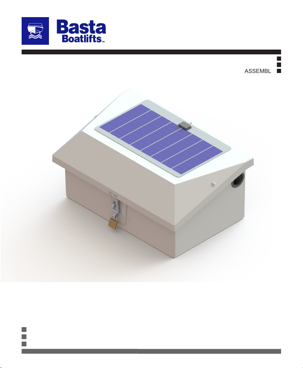
Basta Boatlifts Over-Center Manual
tm
STANDARD & DUAL POWER PACKAGES
Specifications subject to change.
07/20 L392-0109A
REPLACEMENT PARTS
INSTALLATION
ASSEMBLY
Over-Center Solar / Hydraulic Boat Lifts
866.GoBasta
www.gobasta.com
© Basta, Inc. 2020
23
Manufactured under numerous U.S. and foreign patents.
For a complete list, visit bastaboatlifts.com/patents
Always carefully review complete
manual before any assembly or use of
the product. Improper use or failure
to follow instructions or warnings in
manual can cause property damage,
serious injury, or death.
Always use AGM batteries and follow battery manufacturer’s
warnings and instructions. Improper use, or use of other
batteries, have the potential to produce flammable hydrogen
gas which can result in serious injury or death.
DANGER
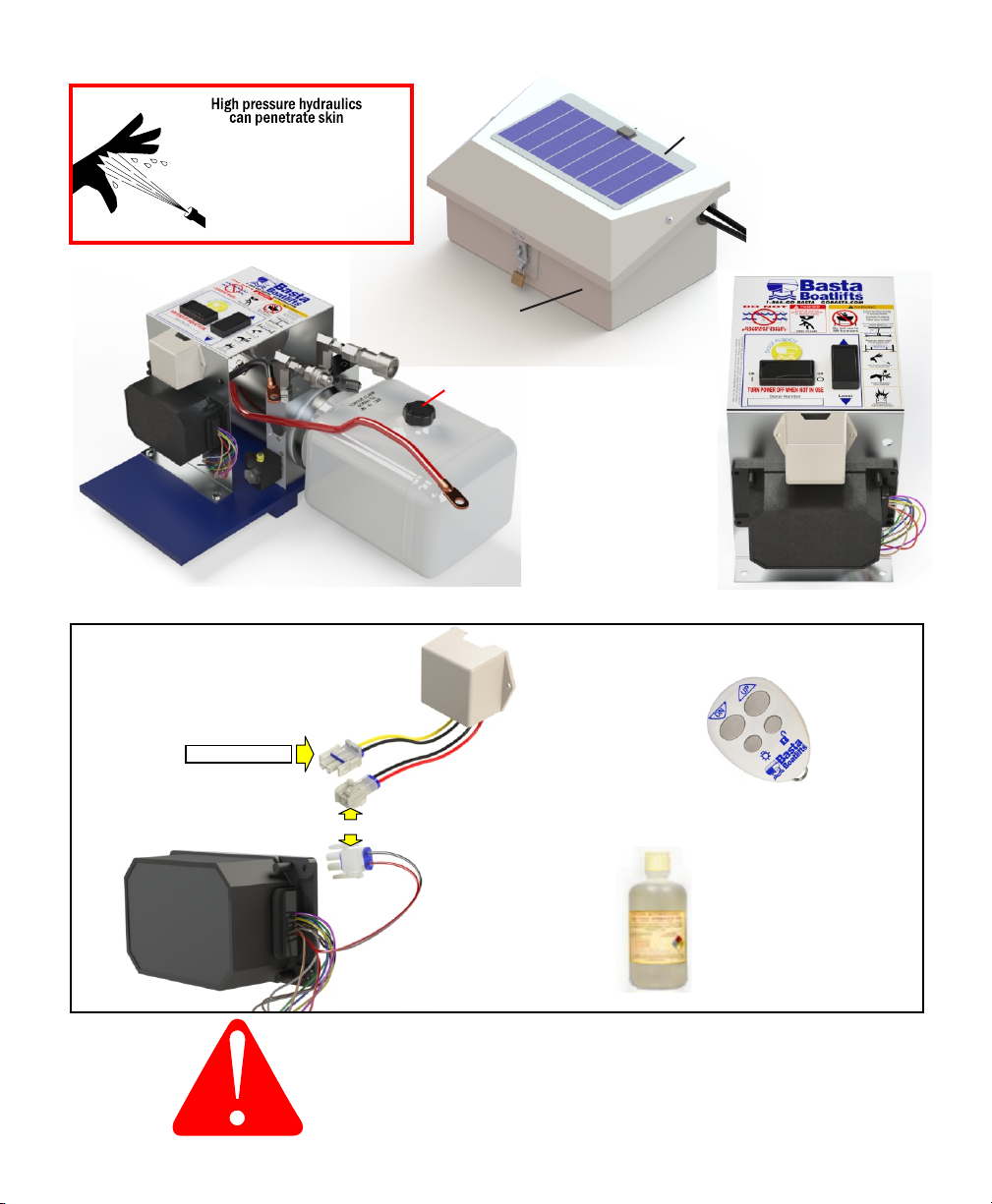
Your Basta Boatlift requires very little maintenance once installed.
Occasionally wipe the solar panel with a clean, damp cloth to preserve its charging performance.
Every 6 months, we recommend:
Inspect the hoses, cylinders and fittings for leaks and wear.
Check the wire terminals for snugness and corrosion.
We STRONGLY recommend the use of a maintenence - free AGM type battery.
In a flooded cell type battery, the electrolyte should be slightly above the indicator ring in each cell.
Carefully add DISTILLED water if necessary. Do not over-fill.
Check the hydraulic fluid level.
The hydraulic fluid level should be about one inch below the top of the reservoir with the lift DOWN.
DO NOT add fluid with the lift in the raised position!
Use only Basta Boatlifts biodegradable non-toxic hydraulic fluid.
INSPECT
the lift monthly
for frayed hoses, loose
fasteners and corrosion
WARNING
REMOTE CONTROL INFORMATION:
Q: HOW MUCH SUN DOES THE SOLAR PANEL NEED?
The panel should receive constant sun for at least 8 hours a day.
Q: IS THE HYDRAULIC FLUID SAFE FOR FISH?
We use a special low-toxicity hydraulic fluid that is safe for the
environment. This mineral oil based fluid is different than food-grade
oil. Only use Basta Boatlifts approved fluid in your hydraulic system.
Q: HOW DO I CHANGE THE HYDRAULIC FLUID?
Our fluid should not require replacement for a considerable amount
of time. If yours has been contaminated or the hydraulic power unit
has been replaced, visit our web site at www.gobasta.com for
detailed instructions.
POWER-UP
At power-up the remote fob function has a ten second delay. Failure to
wait for this ten seconds can make the wait time much longer.
LIFT OPERATION
The remote fob is non-functional until it is enabled by depressing
the unlock (lower right) button momentarily. After the initial ten
second delay, depressing the unlock button enables operation using
the remote fob. The lockout is re-enabled after 60 seconds without a
button press.
Lift operation using the fob is limited to 120 seconds of continuous
operation. If a longer cycle is needed it is necessary to release and
then re-depress the button.
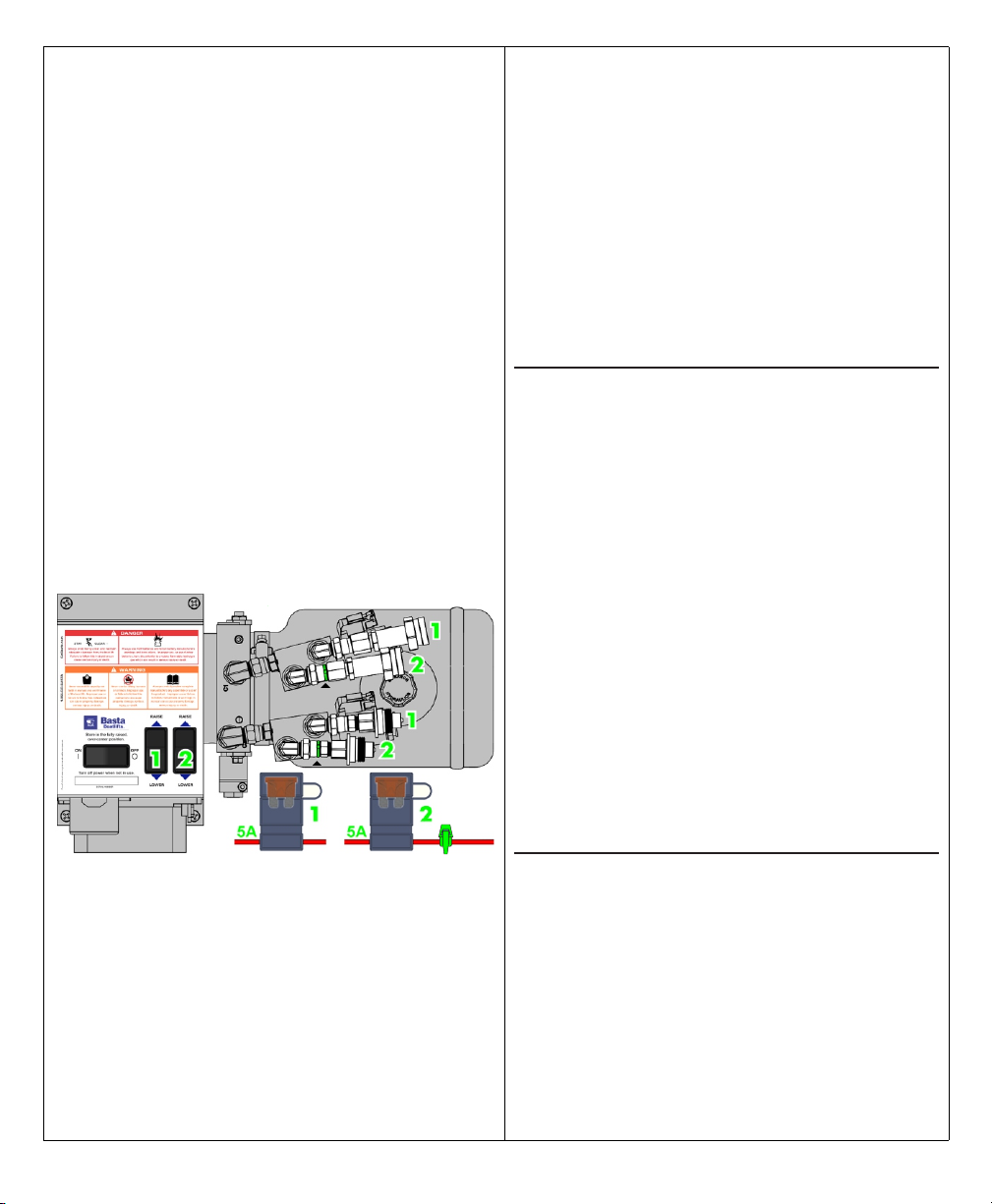
STANDARD POWER UNIT FOB PROGRAMMING
At initial power up there is a five second window when it is possible to
reprogram the receiver to enroll a remote fob. Up to four fobs may be
enrolled. If a fifth fob is enrolled, the first enrolled fob will fall off the list.
To enroll a fob, turn off the power to the lift for fifteen or more seconds.
When power is turned back on press both the UP and DOWN buttons
on the fob simultaneously. This must be done within the first five
seconds after power is applied.
DUAL POWER UNIT FOB PROGRAMMING
The control unit contains two separate lift control computers. Up to four
fobs may be enrolled for each lift. If a fifth fob is enrolled, the first
enrolled fob will fall off the list.
In addition to the 15 amp master fuse, each computer has its own 5
amp fuse. The lift attached to the Quick Disconnect fittings labeled
“1” below is contolled by Switch 1 and powered by Fuse 1.
FOR ASSISTANCE OR SERVICE:
Contact your local dealer or call 1 - 866 - GO - BASTA
IF THE PUMP DOESN’T RUN :
IF THE BATTERY WILL NOT HOLD A CHARGE:
1. Verify that the loaded boat is not exceeding the weight capacity of
the lift. If the battery is a flooded-cell type, check the electrolyte
level.
2. Ensure the solar panel is properly connected.
3. Re-align the solar panel for proper exposure to the sun.
4. Recharge the battery with a 10 amp charger and check the
charge again.
5. Have the battery tested. It may be old and require replacement.
6. If the lift is being used frequently during the day, it may be
necessary to use a 110-volt maintainer/charger.
IF THE REMOTE CONTROL IS NOT FUNCTIONING:
IF THE PUMP RUNS, BUT THE LIFT DOESN’T MOVE:
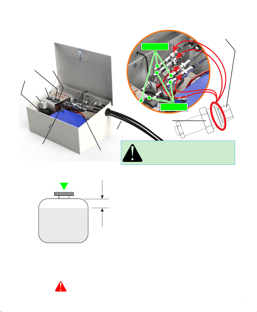
1. Check the 'quick couplers' in the Power Unit. If they are not
screwed together tight enough, the built-in check valves will not
allow fluid to flow. See Pages 4 & 6.
2. Check the fluid level. See Pages 4 & 6.
1. The battery in the key fob transmitter may be low. Replace it with a
new lithium CR2032. These are widely available at variety, hardware
and even grocery stores. Polarity is marked on the battery holder.
2. Verify that the power unit battery is charged and connections are
tight.
3. Reprogram the remote key fobs.
1. Check the battery charge and recharge if necessary.
2. Check the battery connections, clean and re-secure if necessary.
LIGHTING CIRCUIT
The lighting circuit is activated whenever the lift is operated. The
lights stay on for 2 minutes after the lift is operated and may be
manually operated by depressing the lower left button on the remote
Fob. When manually enabled the lights will automatically turn off
after 4 minutes. This is prevents accidental battery discharge.
STORAGE
Always leave the boat in the fully raised, Over-Center™ position with
the power off.
TM
LOW BATTERY LOCKOUT
This control incorporates a low voltage lockout which is intended to
protect the battery from abuse and over-discharge. When the battery
drops below the low battery threshold during pump operation, further
activation using the fob is not allowed. The battery needs to be
checked prior to further operation. The manual switches will allow
the lift to operate if sufficient battery power is present.
To enroll a fob for Lift 1, turn off the power to the lift for at least fifteen
seconds. Remove the fuse for Lift 2 ( indicated by a colored cable tie
installed next to the fuse holder).Turn the power back on and within 5
seconds press both the UP and DOWN buttons on the fob
simultaneously. Turn the power off and repeat for the next fob.
Replace the fuse for Lift 2 when done.
At power up there is a five second window when it is possible to
reprogram the unit to enroll a remote fob. While enrolling the fobs for
one lift, the computer for the other lift must be disabled by
unplugging its fuse.
To enroll a fob for Lift 2, turn off the power to the lift for at least fifteen
seconds. Remove the fuse for Lift 1 ( NO cable tie installed next to the
fuse holder).Turn the power back on and within 5 seconds press both
the UP and DOWN buttons on the fob simultaneously. Turn the power
off and repeat for the next fob. Replace the fuse for Lift 1 when done.
QUICK
DISCONNECT
FITTINGS
QUICK
DISCONNECT
FITTINGS
CABLE
TIE
TIE
TIE
23
Manufactured under numerous U.S. and foreign patents.
For a complete list, visit bastaboatlifts.com/patents
Always carefully review complete
manual before any assembly or use of
the product. Improper use or failure
to follow instructions or warnings in
manual can cause property damage,
serious injury, or death.
Always use AGM batteries and follow battery manufacturer’s
warnings and instructions. Improper use, or use of other
batteries, have the potential to produce flammable hydrogen
gas which can result in serious injury or death.
DANGER
Your Basta Boatlift requires very little maintenance once installed.
Occasionally wipe the solar panel with a clean, damp cloth to preserve its charging performance.
Every 6 months, we recommend:
Inspect the hoses, cylinders and fittings for leaks and wear.
Check the wire terminals for snugness and corrosion.
We STRONGLY recommend the use of a maintenence - free AGM type battery.
In a flooded cell type battery, the electrolyte should be slightly above the indicator ring in each cell.
Carefully add DISTILLED water if necessary. Do not over-fill.
Check the hydraulic fluid level.
The hydraulic fluid level should be about one inch below the top of the reservoir with the lift DOWN.
DO NOT add fluid with the lift in the raised position!
Use only Basta Boatlifts biodegradable non-toxic hydraulic fluid.
INSPECT
the lift monthly
for frayed hoses, loose
fasteners and corrosion
WARNING
REMOTE CONTROL INFORMATION:
Q: HOW MUCH SUN DOES THE SOLAR PANEL NEED?
The panel should receive constant sun for at least 8 hours a day.
Q: IS THE HYDRAULIC FLUID SAFE FOR FISH?
We use a special low-toxicity hydraulic fluid that is safe for the
environment. This mineral oil based fluid is different than food-grade
oil. Only use Basta Boatlifts approved fluid in your hydraulic system.
Q: HOW DO I CHANGE THE HYDRAULIC FLUID?
Our fluid should not require replacement for a considerable amount
of time. If yours has been contaminated or the hydraulic power unit
has been replaced, visit our web site at www.gobasta.com for
detailed instructions.
POWER-UP
At power-up the remote fob function has a ten second delay. Failure to
wait for this ten seconds can make the wait time much longer.
LIFT OPERATION
The remote fob is non-functional until it is enabled by depressing
the unlock (lower right) button momentarily. After the initial ten
second delay, depressing the unlock button enables operation using
the remote fob. The lockout is re-enabled after 60 seconds without a
button press.
Lift operation using the fob is limited to 120 seconds of continuous
operation. If a longer cycle is needed it is necessary to release and
then re-depress the button.
STANDARD POWER UNIT FOB PROGRAMMING
At initial power up there is a five second window when it is possible to
reprogram the receiver to enroll a remote fob. Up to four fobs may be
enrolled. If a fifth fob is enrolled, the first enrolled fob will fall off the list.
To enroll a fob, turn off the power to the lift for fifteen or more seconds.
When power is turned back on press both the UP and DOWN buttons
on the fob simultaneously. This must be done within the first five
seconds after power is applied.
DUAL POWER UNIT FOB PROGRAMMING
The control unit contains two separate lift control computers. Up to four
fobs may be enrolled for each lift. If a fifth fob is enrolled, the first
enrolled fob will fall off the list.
In addition to the 15 amp master fuse, each computer has its own 5
amp fuse. The lift attached to the Quick Disconnect fittings labeled
“1” below is contolled by Switch 1 and powered by Fuse 1.
FOR ASSISTANCE OR SERVICE:
Contact your local dealer or call 1 - 866 - GO - BASTA
website: www.gobasta.com email: [email protected]
IF THE PUMP DOESN’T RUN :
IF THE BATTERY WILL NOT HOLD A CHARGE:
1. Verify that the loaded boat is not exceeding the weight capacity of
the lift. If the battery is a flooded-cell type, check the electrolyte
level.
2. Ensure the solar panel is properly connected.
3. Re-align the solar panel for proper exposure to the sun.
4. Recharge the battery with a 10 amp charger and check the
charge again.
5. Have the battery tested. It may be old and require replacement.
6. If the lift is being used frequently during the day, it may be
necessary to use a 110-volt maintainer/charger.
IF THE REMOTE CONTROL IS NOT FUNCTIONING:
IF THE PUMP RUNS, BUT THE LIFT DOESN’T MOVE:
1. Check the 'quick couplers' in the Power Unit. If they are not
screwed together tight enough, the built-in check valves will not
allow fluid to flow. See Pages 4 & 6.
2. Check the fluid level. See Pages 4 & 6.
1. The battery in the key fob transmitter may be low. Replace it with a
new lithium CR2032. These are widely available at variety, hardware
and even grocery stores. Polarity is marked on the battery holder.
2. Verify that the power unit battery is charged and connections are
tight.
3. Reprogram the remote key fobs.
1. Check the battery charge and recharge if necessary.
2. Check the battery connections, clean and re-secure if necessary.
LIGHTING CIRCUIT
The lighting circuit is activated whenever the lift is operated. The
lights stay on for 2 minutes after the lift is operated and may be
manually operated by depressing the lower left button on the remote
Fob. When manually enabled the lights will automatically turn off
after 4 minutes. This is prevents accidental battery discharge.
STORAGE
Always leave the boat in the fully raised, Over-Center™ position with
the power off.
TM
LOW BATTERY LOCKOUT
This control incorporates a low voltage lockout which is intended to
protect the battery from abuse and over-discharge. When the battery
drops below the low battery threshold during pump operation, further
activation using the fob is not allowed. The battery needs to be
checked prior to further operation. The manual switches will allow
the lift to operate if sufficient battery power is present.
To enroll a fob for Lift 1, turn off the power to the lift for at least fifteen
seconds. Remove the fuse for Lift 2 ( indicated by a colored cable tie
installed next to the fuse holder).Turn the power back on and within 5
seconds press both the UP and DOWN buttons on the fob
simultaneously. Turn the power off and repeat for the next fob.
Replace the fuse for Lift 2 when done.
At power up there is a five second window when it is possible to
reprogram the unit to enroll a remote fob. While enrolling the fobs for
one lift, the computer for the other lift must be disabled by
unplugging its fuse.
To enroll a fob for Lift 2, turn off the power to the lift for at least fifteen
seconds. Remove the fuse for Lift 1 ( NO cable tie installed next to the
fuse holder).Turn the power back on and within 5 seconds press both
the UP and DOWN buttons on the fob simultaneously. Turn the power
off and repeat for the next fob. Replace the fuse for Lift 1 when done.
QUICK
DISCONNECT
FITTINGS
QUICK
DISCONNECT
FITTINGS
CABLE
TIE
TIE
TIE
7. Test the lift on dry ground using the Up/Down Switch
and the Key Fob Transmitters. Inspect the system
for leaks.
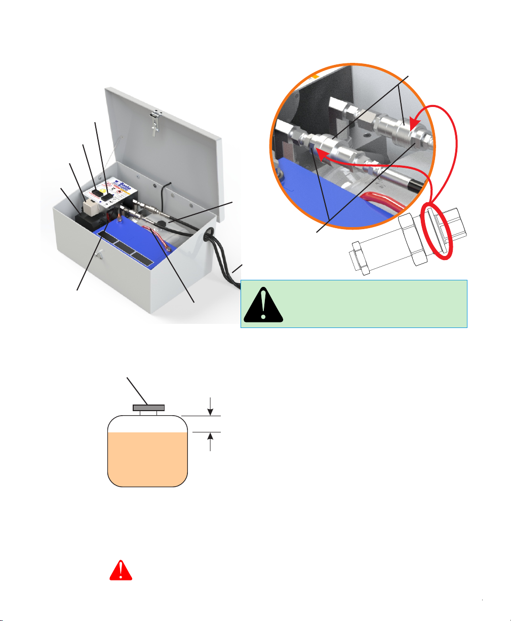
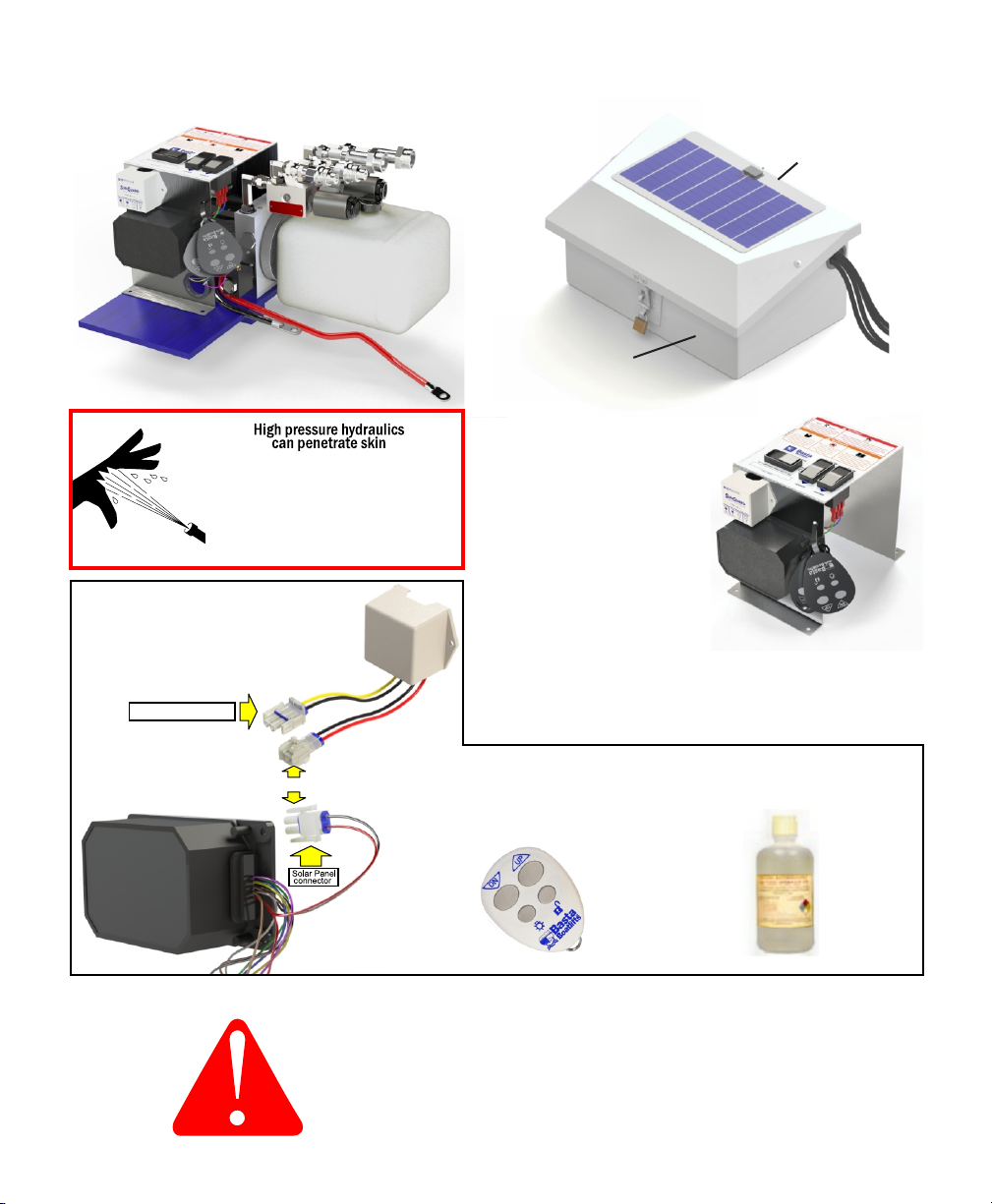
1. The Hydraulic Power Unit will arrive fully assembled.
Make sure all the connections are snug to prevent
leaks or loss of power to the unit.
NOTE: Ensure battery cables are correctly connected
4. Slide the Hydraulic Hose Assembly through the
access hole in the side of the fiberglass Enclosure
and attach the ends to their corresponding
Quick Couplers.
and their terminals are tight (use a wrench).
Ensure each Quick Coupler is
completely seated and tight with
no gap at the connection joint.
Connection must be tight to open internal
check valve and allow fluid to flow. USE PLIERS
DO NOT SUBMERSE
Keep inside dry
5. Plug the cable from the Solar Panel into the connector
with yellow & black wires that comes from the Solar
Controller (shown above left).
NO GAP!
Prevent unauthorized use -
KEEP BOX LOCKED
2.
COMPLETE POWER PACKAGE
# H653-0013
power
switch
POSITIVE BATTERY
CABLE (RED)
# R711-1010
NEGATIVE BATTERY
CABLE (BLACK)
# R711-1005
HOSE ASSEMBLY
# H123-0001
remote
receiver
up/down
switch
MALE QUICK COUPLER
# H700-0020
FEMALE QUICK COUPLER
# H700-0019
6. Read the Operating Instructions in the Owner’s Manual.
NOTE:
REMOVE SHIPPING PLUG IN
RESERVOIR AND REPLACE
WITH BREATHER PLUG
BEFORE START-UP
NOTE:
REMOVE SHIPPING PLUG IN
RESERVOIR AND REPLACE
WITH BREATHER PLUG
BEFORE START-UP
3. Replace the reservoir tank shipping plug with the
included breather plug.
solar
controller
one
inch
hydraulic fluid level with
lift in DOWN position
breather
cap
REPLACE SHIPPING PLUG
WITH BREATHER CAP
(ATTACHED TO CONTROL PANEL)
28
# R811-0010
Remote Control Receiver
with Fobs
Remote Key Fobs
POWER UNIT
ASSEMBLY
# H603-0003 Please order replacement parts by PART NO. and DESCRIPTION
pre-wired
with wiring
harness
Hydraulic Fluid (quart)
BATTERY SAFETY IS IMPORTANT
Follow all battery manufacturer’s
warnings and safety information.
Padlock
not included
SOLAR PANEL ASSEMBLY
# R281-0004
ENCLOSURE
# C243-0003
# R812-0011 # Y354-0001
# R283-0002
Solar Controller
Connect to Solar Panel
Connected
NOTE:
REMOVE SHIPPING PLUG IN
RESERVOIR AND REPLACE
WITH BREATHER PLUG
BEFORE START-UP
NOTE:
REMOVE SHIPPING PLUG IN
RESERVOIR AND REPLACE
WITH BREATHER PLUG
BEFORE START-UP
CONTROL PANEL
ASSEMBLY
# R815-0008
STANDARD POWER UNIT STANDARD POWER UNIT
45
NOTE: always turn unit OFF when not in use
Install a Group 31 Deep Discharge AGM Battery as
shown above. Be sure to connect the Red Battery
Cable to th e positive terminal and the Black Battery
Cable to the negative terminal.
OIL INJECTED INTO THE SKIN FROM HIGH
PRESSURE LEAKS IN HYDRAULIC SYSTEMS
CAN CAUSE SEVERE INJURY. MOST DAMAGE
OCCURS DURING THE FIRST FEW HOURS.
SEEK MEDICAL ATTENTION IMMEDIATELY.
SURGICAL REMOVAL OF OIL MAY BE
NECESSARY.
7. Test the lift on dry ground using the Up/Down Switch
and the Key Fob Transmitters. Inspect the system
for leaks.
1. The Hydraulic Power Unit will arrive fully assembled.
Make sure all the connections are snug to prevent
leaks or loss of power to the unit.
NOTE: Ensure battery cables are correctly connected
4. Slide the Hydraulic Hose Assembly through the
access hole in the side of the fiberglass Enclosure
and attach the ends to their corresponding
Quick Couplers.
and their terminals are tight (use a wrench).
Ensure each Quick Coupler is
completely seated and tight with
no gap at the connection joint.
Connection must be tight to open internal
check valve and allow fluid to flow. USE PLIERS
DO NOT SUBMERSE
Keep inside dry
5. Plug the cable from the Solar Panel into the connector
with yellow & black wires that comes from the Solar
Controller (shown above left).
NO GAP!
Prevent unauthorized use -
KEEP BOX LOCKED
2.
COMPLETE POWER PACKAGE
# H653-0013
power
switch
POSITIVE BATTERY
CABLE (RED)
# R711-1010
NEGATIVE BATTERY
CABLE (BLACK)
# R711-1005
HOSE ASSEMBLY
# H123-0001
remote
receiver
up/down
switch
MALE QUICK COUPLER
# H700-0020
FEMALE QUICK COUPLER
# H700-0019
6. Read the Operating Instructions in the Owner’s Manual.
NOTE:
REMOVE SHIPPING PLUG IN
RESERVOIR AND REPLACE
WITH BREATHER PLUG
BEFORE START-UP
NOTE:
REMOVE SHIPPING PLUG IN
RESERVOIR AND REPLACE
WITH BREATHER PLUG
BEFORE START-UP
3. Replace the reservoir tank shipping plug with the
included breather plug.
solar
controller
one
inch
hydraulic fluid level with
lift in DOWN position
breather
cap
REPLACE SHIPPING PLUG
WITH BREATHER CAP
(ATTACHED TO CONTROL PANEL)
28
# R811-0010
Remote Control Receiver
with Fobs
Remote Key Fobs
POWER UNIT
ASSEMBLY
# H603-0003 Please order replacement parts by PART NO. and DESCRIPTION
pre-wired
with wiring
harness
Hydraulic Fluid (quart)
BATTERY SAFETY IS IMPORTANT
Follow all battery manufacturer’s
warnings and safety information.
Padlock
not included
SOLAR PANEL ASSEMBLY
# R281-0004
ENCLOSURE
# C243-0003
# R812-0011 # Y354-0001
# R283-0002
Solar Controller
Connect to Solar Panel
Connected
NOTE:
REMOVE SHIPPING PLUG IN
RESERVOIR AND REPLACE
WITH BREATHER PLUG
BEFORE START-UP
NOTE:
REMOVE SHIPPING PLUG IN
RESERVOIR AND REPLACE
WITH BREATHER PLUG
BEFORE START-UP
CONTROL PANEL
ASSEMBLY
# R815-0008
STANDARD POWER UNIT STANDARD POWER UNIT
45
NOTE: always turn unit OFF when not in use
Install a Group 31 Deep Discharge AGM Battery as
shown above. Be sure to connect the Red Battery
Cable to th e positive terminal and the Black Battery
Cable to the negative terminal.
OIL INJECTED INTO THE SKIN FROM HIGH
PRESSURE LEAKS IN HYDRAULIC SYSTEMS
CAN CAUSE SEVERE INJURY. MOST DAMAGE
OCCURS DURING THE FIRST FEW HOURS.
SEEK MEDICAL ATTENTION IMMEDIATELY.
SURGICAL REMOVAL OF OIL MAY BE
NECESSARY.
NOTE: always turn unit OFF when not in use
DUAL POWER UNIT
# R811-0010
Remote Control
Receiver with Fobs Remote Key Fobs Hydraulic Fluid (quart)
# R812-0016 # Y354-0001
# R283-0002
Solar Controller
Connect to Solar Panel
Connected
POWER UNIT
SUB-ASSEMBLY
# H603-0015
Padlock
not included
SOLAR PANEL
# R281-0004
ENCLOSURE
# C243-0004
pre-wired
with wiring
harness
CONTROL PANEL
ASSEMBLY
# R815-0011
Please order replacement parts by PART NO. and DESCRIPTION
USE ONLY BASTA BOATLIFTS
BIODEGRADABLE HYDRAULIC FLUID
OIL INJECTED INTO THE SKIN FROM HIGH
PRESSURE LEAKS IN HYDRAULIC SYSTEMS
CAN CAUSE SEVERE INJURY. MOST DAMAGE
OCCURS DURING THE FIRST FEW HOURS.
SEEK MEDICAL ATTENTION IMMEDIATELY.
SURGICAL REMOVAL OF OIL MAY BE
NECESSARY.
one
inch
only add fluid with lift
in DOWN position
Ensure each Quick Coupler is
completely seated and tight with
no gap at the connection joint.
Connection must be tight to open internal
check valve and allow fluid to flow. USE PLIERS
DO NOT SUBMERSE
Keep inside dry
NO GAP!
Prevent unauthorized use -
KEEP BOX LOCKED
hydraulic fluid level shown
with lift in DOWN position
COMPLETE POWER UNIT
# H653-0015
power
switch
POSITIVE BATTERY
CABLE (RED)
# R711-1010
NEGATIVE BATTERY
CABLE (BLACK)
# R711-1005
HOSE ASSEMBLIES
# H123-0001
remote
receiver
up/down
switch
LIFT2
MALE QUICK COUPLER
# H700-0020
FEMALE QUICK COUPLER
# H700-0019
solar
controller
1. The Hydraulic Power Unit will arrive fully assembled. Make sure
all the connections are snug to prevent leaks or loss of power to
the unit.
2. Install a Group 31 Deep Discharge AGM battery as shown. Be
sure to connect the red battery cable to the positive terminal and
the black battery cable to the negative terminal.
NOTE: Ensure the battery cables are correctly connected and their
terminals are tight (use a wrench).
3. Slide each hydraulic hose assembly through the access hole in
the side of the fiberglass enclosure and attach the end to its
corresponding quick couplers.
4. Plug the cable from the solar panel into the connector on the
wiring harness that comes from the solar controller as shown
above left.
5. Read the Operating Instructions in the Owner’s Manual.
6. Test the lift on dry ground using the UP/DOWN switch and the
key fob transmitters.
7. Inspect the system for leaks.
up/down
switch
LIFT1
LIFT 1
LIFT 2
DUAL POWER UNIT
67
BATTERY SAFETY IS IMPORTANT
Follow all battery manufacturer’s
warnings and safety information.

Product Information
Serial #:_________________________________________
Date of purchase: _________________________________
Purchased from: __________________________________
Contact name: ___________________________________
Phone number: __________________________________
Notes: __________________________________________
________________________________________________
________________________________________________
WARRANTY: Basta Inc. dba Basta Boatlifts (“Company”) warrants its Products for non-commercial use for
a period of three (3) years, to the original Purchaser (“Purchaser”) against manufacturing defects in all Product materials
and workmanship beginning from date of purchase of the Product from Company. If the Product is purchased from an
authorized Company Reseller, the warranty term begins upon the date the Product is sold to the end Purchaser or three
(3) months from the date the Product is shipped from Company, whichever occurs first. Under the following terms and
conditions:
NOTICE REQUIREMENTS AND REMEDIES: If the Purchaser discovers a defect, the Company, or its
authorized Company dealer or agent, will, at the Company's options: (1) repair the Product, (2) replace the defective part,
or (3) refund the purchase price of the Product upon confirmation by Company the Product is defective, provided that the
Company receives notice of the defect from the Purchaser or Company authorized agent before the warranty period
lapses. Product changes caused by age or environment (such as marine growth, heat corrosion or electrolysis) shall not
constitute a defect. Confirmation of the defect shall require that reasonable proof of the defect be provided by Purchaser
to Company or Company authorized agent, and may include that the Product or part be returned to Company for
inspection at Purchaser's initial expense. This warranty shall not apply if Company receives notification after the before-
stated deadline, regardless of when the defect occurred or was discovered, and regardless of the reason for the delay in
notification. “Notification” shall be deemed to have occurred when the Purchaser or Company authorized agent sends
written notice to Company by fax or by e-mail and when receipt is confirmed by Company's response.
EXCLUSIONS: This warranty does not apply to damages caused by or due to : (1) accident (including,
without limitation, collision, fire, flood, wind, ice or any other natural disaster or acts of God), abuse, misuse, overloading,
out of level or improper boat loading (i.e.: not fully on, too far on, or crooked on lift), or (2) faulty assembly or installation in
the event such assembly or installation was not performed by a Company employee or Company authorized agent.
Company is not responsible for determining the weight or dimensions of Purchaser's boat, and Purchaser is advised that
published boat specifications are often inaccurate. This warranty is void if the Product has been modified without the
permission of the Company or if any Company serial number has been removed or defaced. Normal maintenance
requires an annual inspection of the Product by a Company employee or Company authorized agent, including bolts, pins,
hydraulics, pump, electronics, and welds and failure to undertake such maintenance may constitute “abuse”. Lift
components' fluid level and condition, including battery water and acid, hydraulic fluid and strainer cleaning are
maintenance items and are not covered by this warranty. Zincs, ropes, batteries, cosmetic concerns and custom coatings
are not covered by this warranty. Batteries supplied by Company that are maintained in top operating condition by
Purchaser are warranted for a period of one (1) year. If any Company Product is used in brackish or salt water, the
Purchaser agrees that proper maintenance requires that the Purchaser shall attach to the Product, maintain and regularly
check sacrificial anodes, also known as “zincs,” in order to prevent electrolysis from damaging the lift metals, and that
failure to attach and maintain the zincs constitutes “abuse.” This warranty does not void or alter any rights the Purchaser
may have against authorized agents or suppliers of component parts.
LIMITATIONS: To the maximum extent permitted by law except as expressly stated herein, there are no
warranties, expressed or implied, by operation of law or otherwise, of the Product furnished under this Agreement. Seller
disclaims any implied warranty of merchantability or fitness for a particular purpose. The sole remedy for liability of any
kind shall be limited to the remedies provided in this warranty and shall in no event include any incidental, indirect, special
or consequential damages or loss of use, revenue or profit. Should the company nevertheless be found liable for any
damages the total liability of the company shall be limited to the purchase price of the product
BASTA BOATLIFTS LIMITED WARRANTY
Registration is REQUIRED for valid warranty
Go to www.bastaboatlifts.com/support/
Basta Boatlifts Bellevue WA 98005 USA
8
Other Basta Boatlifts Boating Equipment manuals


Popular Boating Equipment manuals by other brands


Humphree
Humphree HCS-5 installation manual

Vetus
Vetus BOW4512D Operation manual and installation instructions

Dock Doctors
Dock Doctors SLIDING BOARDING STEP Assembly instructions

Mastervolt
Mastervolt Mass Combi 12/2000-100 Quick installation

SeaView
SeaView PM5-FMD-8 installation instructions

Hobie
Hobie Mirage 360 manual


