Bastian Solutions BRBAC 1 HP Manual
Installation and Maintenance Manual
Model: BRBAC 1 HP
Effective December 2019
Rev.A1

Installation & Maintenance Manual: BRBAC 1 HP
Published December 2019 Rev.A1 2
Contributions
ROLE
NAME
TITLE
Author
Rajarshi Choudhuri
Design and Cost Engineer
Checker
Ben Baker
Senior Design Engineer
Approver
Chris Perry
Engineering Manager
Revision History
DATE
REVISION
REVISION DESCRIPTION
AUTHOR
12/05/2019
A1
Initial document creation
Rajarshi Choudhuri

Installation & Maintenance Manual: BRBAC 1 HP
Published December 2019 Rev.A1 3
Term and Acronym Definitions
TERM/ACRONYM
DEFINITION
AC
Alternating current
BF
Between frame; this refers to the distance between conveyor bed side frames.
BHCS
Button head cap screw
BOM
Bill of Materials
BRBAC
Belt Over Roller Bed Alternating Current; Format of AC conveyor used for
cartons, cases, or totes transport optimized for long runs. Low friction option for
conveying cartons, cases, or totes of various shapes, sizes, and weights using
rollers to support the belt.
BRBACI
Belt Over Roller Bed Alternating Current Incline; Inclined BRBAC.
BSBAC
Belt Over Slider Bed Alternating Current; Format of AC conveyor used for carton,
case, or tote transport optimized for long runs. Low friction option for conveying
carton, case, or tote or various shapes, sizes, and weights using sheet steel to
support the belt.
BSBACI
Belted Slider Bed Alternating Current Incline; Inclined BSBAC
CB
Carriage bolt
CCW
Counter-clockwise
Center Drive
Drive format of AC conveyor where the drive unit is mounted at any point along
the length of the conveyor.
CW
Clockwise
Discharge
The point where cartons, cases, or totes exit a conveyor or similar unit used in a
material handling system.
FAT
Factory Acceptance Testing
Flange
A feature in sheet metal consisting of a face and bend connected to an existing
face along a straight edge.
Glide Top
An AC belt format with a low coefficient of friction designed to allow cartons,
cases, or totes to slide across the conveying surface.
Guide Rail
Mechanism used to maintain the desired position of conveyable cartons, cases,
or totes on their respective conveying surface.
HHCS
Hex head cap screw
ID
Inner diameter of a circular, cylindrical or arced body.
Idler Roller
Cylindrically-shaped material handling component that is unpowered and used
to support a belt.
Infeed
The point where cartons, cases, or totes enter a conveyor or similar unit used in
a material handling system.
Live
A zone of conveyor runs "live" when it runs whenever energized. It is for this
reason that live zones of conveyor do not have or need any photoeyes or
reflectors.

Installation & Maintenance Manual: BRBAC 1 HP
Published December 2019 Rev.A1 4
TERM/ACRONYM
DEFINITION
Longitudinal Rib
A belt format with a rib texture aligned with the belt’s direction of travel.
LOTO
Lockout Tagout
Mark Number
A numeric or alphanumeric term used to uniquely identify a conveyor bed or
collection of beds (of similar model type) within a material handling system.
Match
A mark made on mating conveyor assemblies to assist in identifying orientation
and placement within a system.
Noseover
An arced conveyor used to make a smooth transition between conveying
surfaces of differing incline or decline angles.
OAW
Overall width of any given conveyor bed.
OD
Outer diameter of a circular, cylindrical, or arced body.
OSHA
Occupational Safety and Health Administration
Polytier
Heavy duty floor support with a wide stance, capable of supporting multiple
levels and types of conveyor.
Power feeder
A section of BLVDC that will always be at the infeed of an inclined AC or the
discharge section of a declined AC.
PPE
Personal protective equipment
Pulley
Mechanical device used to change the direction of the belt in a conveyor system,
to drive and/or tension the belt.
Return Idlers
Belt-routing rollers on the underside of any given AC conveyor.
Roller
Powered or unpowered cylindrically-shaped material handling component used
for mechanical power transmission, a conveying surface, and/or support for a
belted conveying surface.
Side Cover
A PVC cover used to conceal and protect electrical components and wiring from
foreign debris and moving obstacles.
Side Frame
Structural member used to support rotating components needed for conveyor
beds.
Splice Assembly
A five-component assembly-consisting of a plate (or formed plate), two bolts,
and two nuts-that is used to secure a piece of guide rail to an adjacent piece of
guide rail, or a side frame to an adjacent side frame. This is used to provide
additional structural rigidity and ensure relative position of components is
maintained.
Tail Pulley
A non-driven pulley located at the tail end of the conveyor.
Take-up Pulley
Pulley with an adjustable position used to eliminate unnecessary slack in a belt.
Take-up Screws
Adjustment screw used to adjust the position of a take-up pulley.
TOR
Top of roller; this refers to the elevation of the conveying surface with respect to
the floor on which the conveyor is sitting.
Track
To adjust the position of conveyor components in such a way that encourages
proper belt alignment on a system.

Installation & Maintenance Manual: BRBAC 1 HP
Published December 2019 Rev.A1 5
Table of Contents
1Introduction ................................................................................................................... 8
2OSHA and Safety ............................................................................................................ 8
3Model: BRBAC 1 HP ........................................................................................................ 9
3.1 Drive Section.....................................................................................................................10
3.2 Tail Section .......................................................................................................................11
3.3 Bed section .......................................................................................................................12
3.4 Noseover Section ..............................................................................................................13
3.5 Power Feeder Section........................................................................................................14
4Receiving...................................................................................................................... 16
4.1 Mark Numbers..................................................................................................................16
4.2 Skid Contents....................................................................................................................17
4.3 Skid Documentation..........................................................................................................18
5Installation................................................................................................................... 19
5.1 Floor Support Location ......................................................................................................19
5.2 Uniform Levelling and Straightness of Conveyor Section.....................................................20
5.3 Installing the AC Belt .........................................................................................................20
5.4 Tensioning and Tracking the AC belt ..................................................................................23
5.5 Installing and Adjusting Noseover section angle.................................................................25
5.6 Installing Underside Covers ...............................................................................................26
6Maintenance and Operation......................................................................................... 28
6.1 Safety During Operation....................................................................................................28
6.2 Mechanical Maintenance Schedule....................................................................................28
6.3 Electrical Maintenance Schedule........................................................................................29
6.4 Tail Pulley Replacement ....................................................................................................29
6.5 Drive Pulley Replacement..................................................................................................31
6.6 Take-up Pulley Replacement..............................................................................................36
6.7 Snub Roller Replacement...................................................................................................39
6.8 Idler Roller Replacement ...................................................................................................39
6.9 Bearing Replacement and Maintenance.............................................................................40
6.10 AC Motor Replacement .....................................................................................................40
6.11 AC Belt Replacement.........................................................................................................41
7Troubleshooting and Repair.......................................................................................... 42
8Spare Parts................................................................................................................... 43
Appendix 1 Spare Parts - General Arrangements ............................................................ 43

Installation & Maintenance Manual: BRBAC 1 HP
Published December 2019 Rev.A1 6
List of Figures
Figure 1: BRBAC 1HP configuration - exploded view....................................................................................9
Figure 2: BRBAC Incline 1HP configuration - exploded view ......................................................................10
Figure 3: BRBAC 1HP drive section - exploded view...................................................................................11
Figure 4: BRBAC 1HP tail section - exploded view......................................................................................12
Figure 5: BRBAC bed section - exploded view ............................................................................................13
Figure 6: BRBAC noseover section - exploded view....................................................................................14
Figure 7: BRBACI conveyor example with mark number "MK1100" ..........................................................16
Figure 8: BRBAC mark stickers - section 1...................................................................................................17
Figure 9: Skid Sticker...................................................................................................................................18
Figure 10: Diagonal measurement for conveyor section............................................................................20
Figure 11: Belt Routing - BRBAC 1 HP configurations - section view..........................................................21
Figure 12: Belt routing - BRBAC 1 HP drive - section view..........................................................................22
Figure 13: Belt routing - BRBAC 1 HP tail - section view.............................................................................22
Figure 14: Belt routing - BRBAC 1 HP tail with noseover - section view.....................................................22
Figure 15: Belt splicing schematic...............................................................................................................23
Figure 16: BRBAC 1 HP drive take-up view .................................................................................................23
Figure 17: Belt tracking by adjusting snub rollers.......................................................................................24
Figure 18: BRBAC Noseover section - angle adjustment bracket and corresponding hardware ...............25
Figure 19: BRBAC noseover section - location of check dimension............................................................26
Figure 20: Underside cover splice plate install - exploded view.................................................................27
Figure 21: Installing the underside cover to the BRBAC bed section .........................................................27
Figure 22: BRBAC 1 HP tail pulley bracket ..................................................................................................29
Figure 23: BRBAC 1 HP tail pulley take-up hardware..................................................................................30
Figure 24: BRBAC 1 HP tail pulley - lifting tail pulley out of side frame......................................................30
Figure 25: BRBAC 1 HP drive motor connection - exploded view...............................................................32
Figure 26: BRBAC 1 HP drive - underside cover..........................................................................................33
Figure 27: BRBAC 1 HP drive pulley guard..................................................................................................33
Figure 28: BRBAC 1 HP drive pulley bearing ...............................................................................................34
Figure 29: BRBAC 1 HP drive pulley removal from drive section................................................................35
Figure 30: BRBAC 1 HP drive - underside cover..........................................................................................36
Figure 31: BRBAC 1 HP drive take-up pulley bearing - motor side .............................................................37
Figure 32: BRBAC 1 HP drive take-up pulley bearing - non-motor side......................................................37
Figure 33: BRBAC 1 HP drive - take-up pulley removal...............................................................................38
Figure 34: Snub roller bracket.....................................................................................................................39

Installation & Maintenance Manual: BRBAC 1 HP
Published December 2019 Rev.A1 7
List of Tables
Table 1: Troubleshooting guide ..................................................................................................................42
Table 2: General spare parts list for BRBAC................................................................................................43
Reference Documents
Manufacturer
Manual
Habasit Holding AG
Habasit Heavy Conveyor Belts TM120RT-B (H250000385)
Habasit Holding AG
Habasit Heavy Conveyor Belts TM120LR-B (H250000441)
Habasit Holding AG
Habasit Heavy Conveyor Belts UMS130SC-B (H250000560)
Habasit Holding AG
Habasit Product Data Sheet RGLIDE-T
Habasit Holding AG
Habasit Fabric Conveyor Belts Installation and Maintenance Guide (6040)
ABB Motors and
Mechanical Inc
Dodge Quantis RHB Installation and Maintenance Instructions (499322)
Bastian Solutions
ZiPline Conveyor - Installation and Maintenance Manual: BLVDC
Bastian Solutions
ZiPline Conveyor - Side Cover and Guiderail Installation Manual
Bastian Solutions
ZiPline Conveyor - Support Installation Manual

Installation & Maintenance Manual: BRBAC 1 HP
Published December 2019 Rev.A1 8
1Introduction
Thank you for choosing ZiPline Conveyor. The following manual will serve as a guide for installation, part
replacement, and general maintenance for your material handling equipment. It is important to read the
manual and follow any instructions as it provides important safety information for personnel and will
maximize the longevity of the conveyor.
The information contained in this manual applies only to the products described. Uses, activities, or
processes related to installing or maintaining the equipment that are not explicitly described in this
manual are considered out of scope. Please contact Bastian Solutions ZiPline Conveyor for any
questions or support that is not clearly addressed in this document. ZiPline Conveyor is not responsible
for misuse of the equipment described in this manual or misuse of information in this manual. If you
have any questions, contact ZiPline Conveyor Customer Service or Support at
ZiPlineSupport@BastianSolutions.com.
2OSHA and Safety
ZiPline Conveyor is not responsible for ensuring that conveyors used in a system abide by OSHA
standards. Safety is of primary importance to our company, but as a product distributor we ask that
system integrators and end users conform with all applicable OSHA standards. We encourage that all
warnings in this manual are followed to avoid unnecessary risk.
Installation & Maintenance Manual: BRBAC 1 HP
Published December 2019 Rev.A1 9
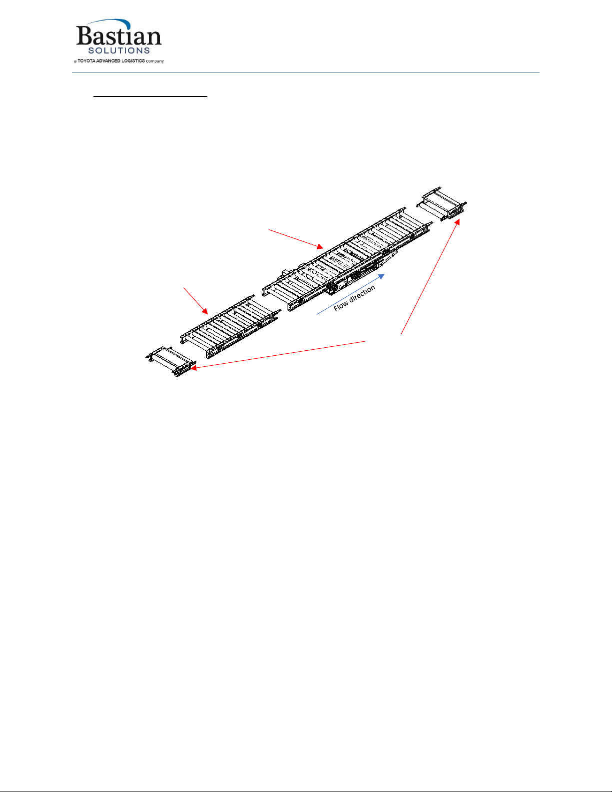
3Model: BRBAC 1 HP
The Belted Roller Bed AC (BRBAC) conveyor is designed to convey product across long distances without
product accumulation. The ZiPline Conveyor BRBAC 1 HP is available in two configurations: straight and
incline/decline. ZiPline Conveyor uses Baldor-Dodge gearmotors to the drive the BRBAC conveyor. Figure
1 illustrates an exploded view of the different sections that constitute a 1HP BRBAC configuration and
some common terms used to describe these sections.
Figure 1: BRBAC 1HP configuration - exploded view
There are five main parts that make up a BRBAC conveyor line: the drive section, the tail section, the
bed sections, the noseover section and the power feeder section. Figure 1 illustrate the drive, tail and
bed sections only. The noseover and power feeder sections are added when there is an elevation
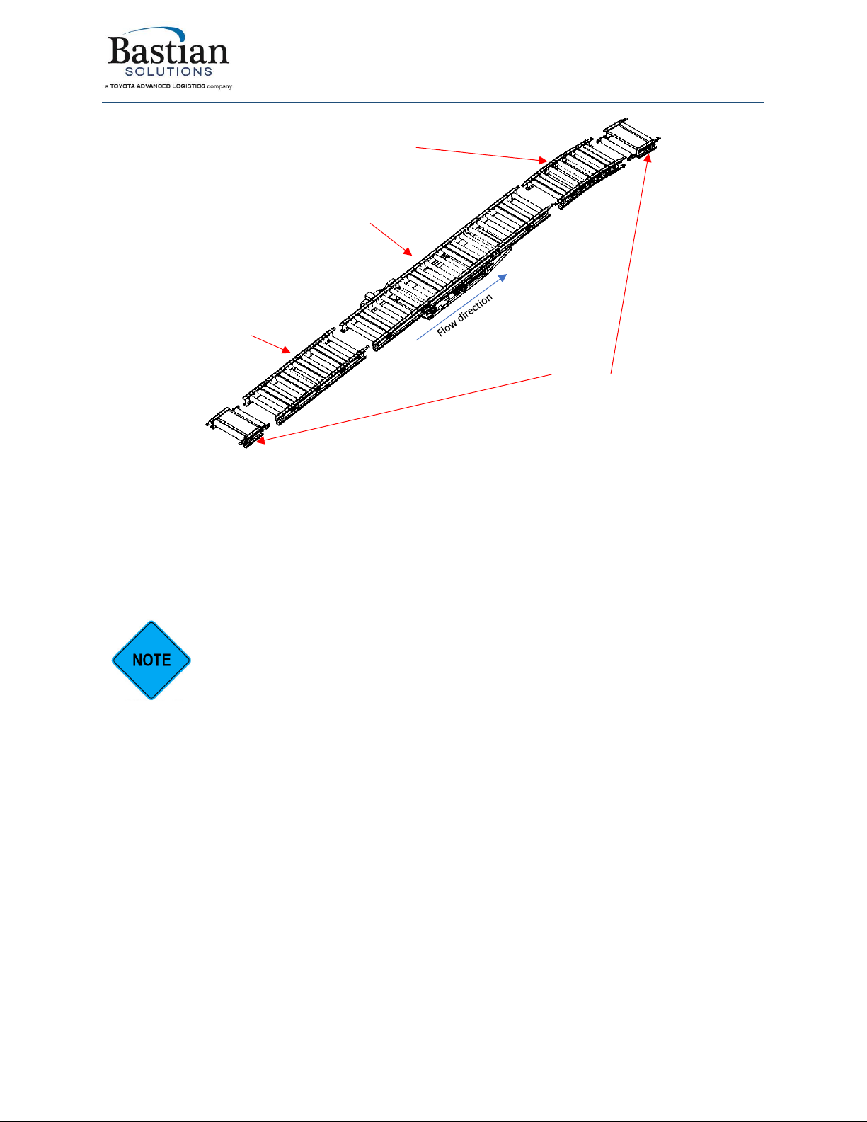
change between the infeed and discharge end of the BRBAC conveyor section. Figure 2 illustrates an
exploded view of the different sections that constitute a 1HP BRBAC inline configuration and some
common terms used to describe these sections.
Bed Section
Tail Section
1HP –motor
side left -
Drive Section
Installation & Maintenance Manual: BRBAC 1 HP
Published December 2019 Rev.A1 10
Figure 2: BRBAC Incline 1HP configuration - exploded view
3.1 Drive Section
The BRBAC drive section is a 10’ conveyor section that contains the motor, take-up subassembly for the
belt tension and the drive pulley. The BRBAC drive sections are offered in 18”, 24”, 30”, and 36” OAW.
The sub-configurations are based on the motor mount side, i.e left-side and right-side sub-
configurations. The motor mount side is determined by facing downstream of the conveyor.
The left-hand and right-hand sub-configuration of the drive sections are not the same
conveyor assembly but are reversible on site with additional spare parts. In case this
switch needs to be made, please contact your ZiPline Conveyor representative.
The drive sections are not designed to run backwards. This makes belt tracking very sensitive and
inconsistent on the BRBAC section. ZiPline Conveyor recommends making the sub-configuration change
with additional spare parts on site. Please contact your ZiPline Conveyor representative for assistance
and information to make the sub-configuration change.
Figure 3 illustrates the BRBAC 1 HP (motor left side) drive section exploded view with a list of spare
parts. Appendix 1 has the general arrangements for the BRBAC 1 HP drive section labelled as GA-
BRBAC-MW-120-0002.
Noseover Section
1HP –motor
side left -
Drive Section
Bed Section
Tail Section
Installation & Maintenance Manual: BRBAC 1 HP
Published December 2019 Rev.A1 11
The BRBAC drive section is designed to be positioned towards the center or biased towards the
downstream of the conveyor section. In extreme cases, the BRBAC 1 HP drive section can be placed
adjacent to two tail sections.
3.2 Tail Section
The BRBAC tail section is a 12” conveyor section that contains the tail pulley and tail pulley take-up
subassembly. The tail sections are always placed as the first and last bed section in a BRBAC section. The
BRBAC tail sections are offered in 18”, 24”, 30” and 36” OAW. Figure 4 illustrates the BRBAC 1HP tail
section exploded view with a list of spare parts. Appendix 1 has the general arrangements for the BRBAC
1HP tail section labelled as GA-BRBAC-MW-12-0001.
Figure 3: BRBAC 1HP drive section - exploded view

Installation & Maintenance Manual: BRBAC 1 HP
Published December 2019 Rev.A1 12
The BRBAC tail sections does not come standard with underside covers. The underside
covers for the BRBAC tail sections need to be ordered separately as an accessory.
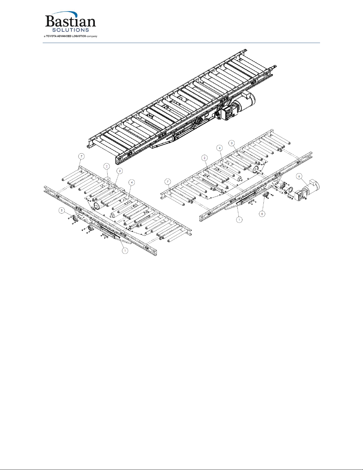
3.3 Bed section
The BRBAC bed section are idler bed sections in the BRBAC conveyor. The BRBAC bed section is offered
in 18”, 24”, 30” and 36” OAW and range between 12” to 120” OAL in 6” increments. The BRBAC bed
sections are identical for all offered BRBAC configurations. Figure 5 illustrates the BRBAC bed section
exploded view with a list of spare parts. Appendix 1 has the general arrangements for the BRBAC bed
section labelled as GA-BRBAC-MW-120-0001.
Figure 4: BRBAC 1HP tail section - exploded view

Installation & Maintenance Manual: BRBAC 1 HP
Published December 2019 Rev.A1 13
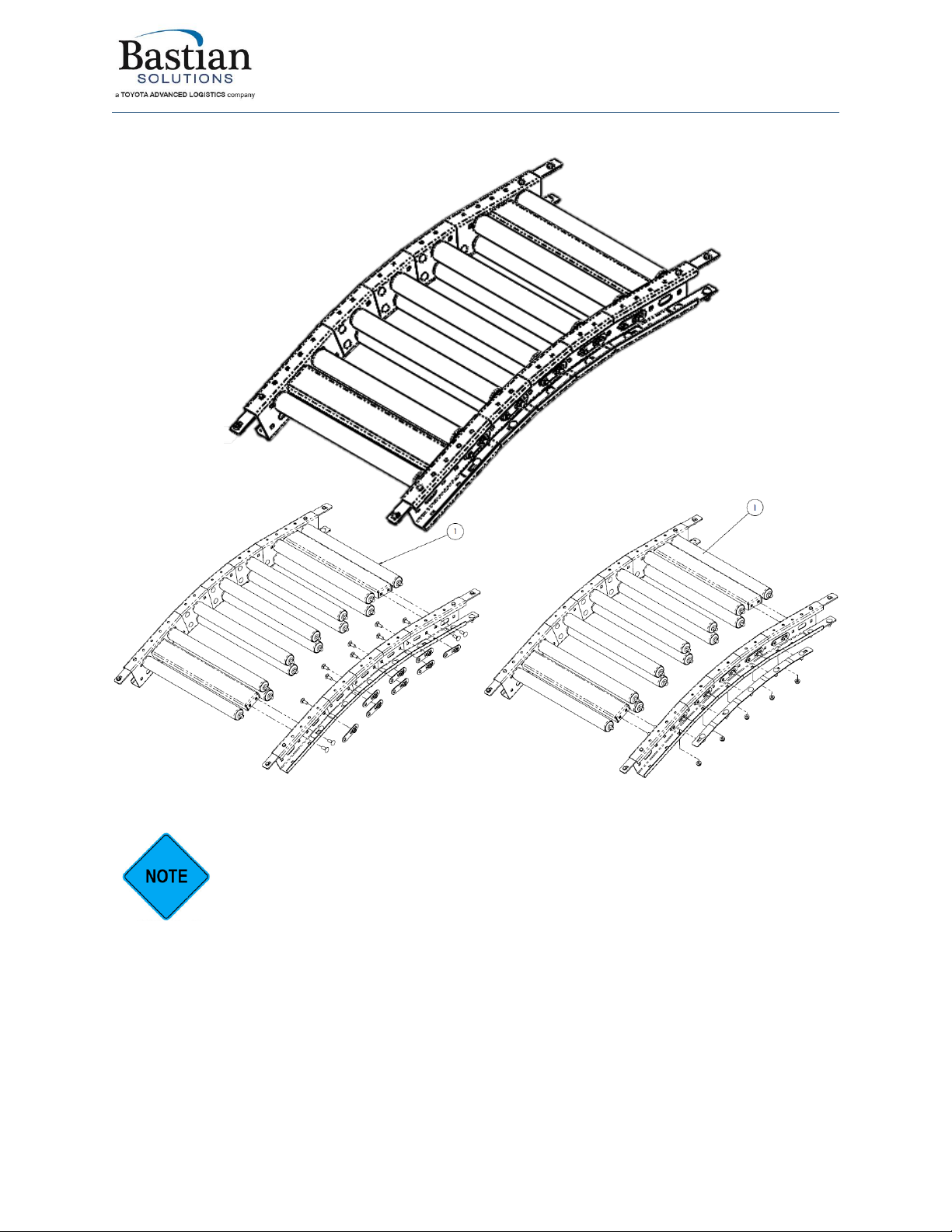
Figure 5: BRBAC bed section - exploded view
The BRBAC bed sections does not come standard with underside covers. The
underside covers for the BRBAC bed sections need to be ordered separately as an
accessory.
3.4 Noseover Section
The BRBAC noseover section is a 42” conveyor section that is vertically sectioned to allow for angular
adjustment between 0 to 25 degrees. The angular adjustment can be made by adjusting the hardware in
the bottom of the channel in the side frame on both sides. The BRBAC noseover section is offered in
18”, 24”, 30” and 36” OAW. The BRBAC noseover section is identical for all BRBAC configurations.
The BRBAC noseover section is a recommended conveyor section for a BRBAC
incline/decline conveyor. An incline/decline BRBAC conveyor without a noseover
section can result in damage to the package conveyed due to rough transitions
between incline/decline and straight sections.
Figure 6 illustrates the BRBAC noseover section exploded view with a list of spare parts. Appendix 1 has
the general arrangements for the BRBAC noseover section labelled as GA-BRBAC-MW-42-0001.
Installation & Maintenance Manual: BRBAC 1 HP
Published December 2019 Rev.A1 14
Figure 6: BRBAC noseover section - exploded view
The BRBAC noseover section does not come standard with underside covers. The
underside covers for the BRBAC noseover section need to be ordered separately as an
accessory.
3.5 Power Feeder Section
The BRBAC power feeder section is a BLVDC conveyor section that is on the upstream section of a
BRBAC incline conveyor, or on the downstream section of a BRBAC decline conveyor. The BRBAC power
feeder section is offered in 18”, 24”, 30” and 36” OAW. The OAL of the power feeder section is
dependent on the system design.

Installation & Maintenance Manual: BRBAC 1 HP
Published December 2019 Rev.A1 15
The BRBAC power feeder section is not on the same mark number as the BRBAC
conveyor on shipment.
The BRBAC power feeder section is a recommended conveyor section for a BRBAC
incline/decline conveyor. An incline/decline BRBAC conveyor without a power feeder
section can result in damages to the package conveyed due to rough transitions
between straight and inline/decline sections.
For more information on the BRBAC power feeder section, please refer to Bastian Solutions ZiPline
Conveyor Installation & Maintenance Manual: BLVDC.
Installation & Maintenance Manual: BRBAC 1 HP
Published December 2019 Rev.A1 16
4Receiving
Upon delivery of any ZiPline Conveyor, please review and check the following:
•The quantity of items received against the Bill of Lading.
•A visual inspection of equipment should be completed to determine any damage that may have
occurred during shipping. If damage is present, document with pictures.
•Review Mark Number information and layout locations. More information can be found in
subsection 4.1 (Mark Numbers).
If there are any missing or damaged components, please contact your ZiPline Conveyor representative
with as much detail as possible. If you are unsure of your ZiPline Conveyor representative, please
4.1 Mark Numbers
A mark number is a specific number given to a piece of equipment. A mark number is usually made up of
a single product line (RZPDC, RLVDC, BZPDC, etc.) but can contain many bed section lengths. They can
range from two inches to hundreds of feet. The mark number is used to help identify where the piece of
equipment will go within the system layout. The mark number for a BRBAC is segmented to its
constituent sections from upstream to downstream. For example, let’s consider a BRBAC section of
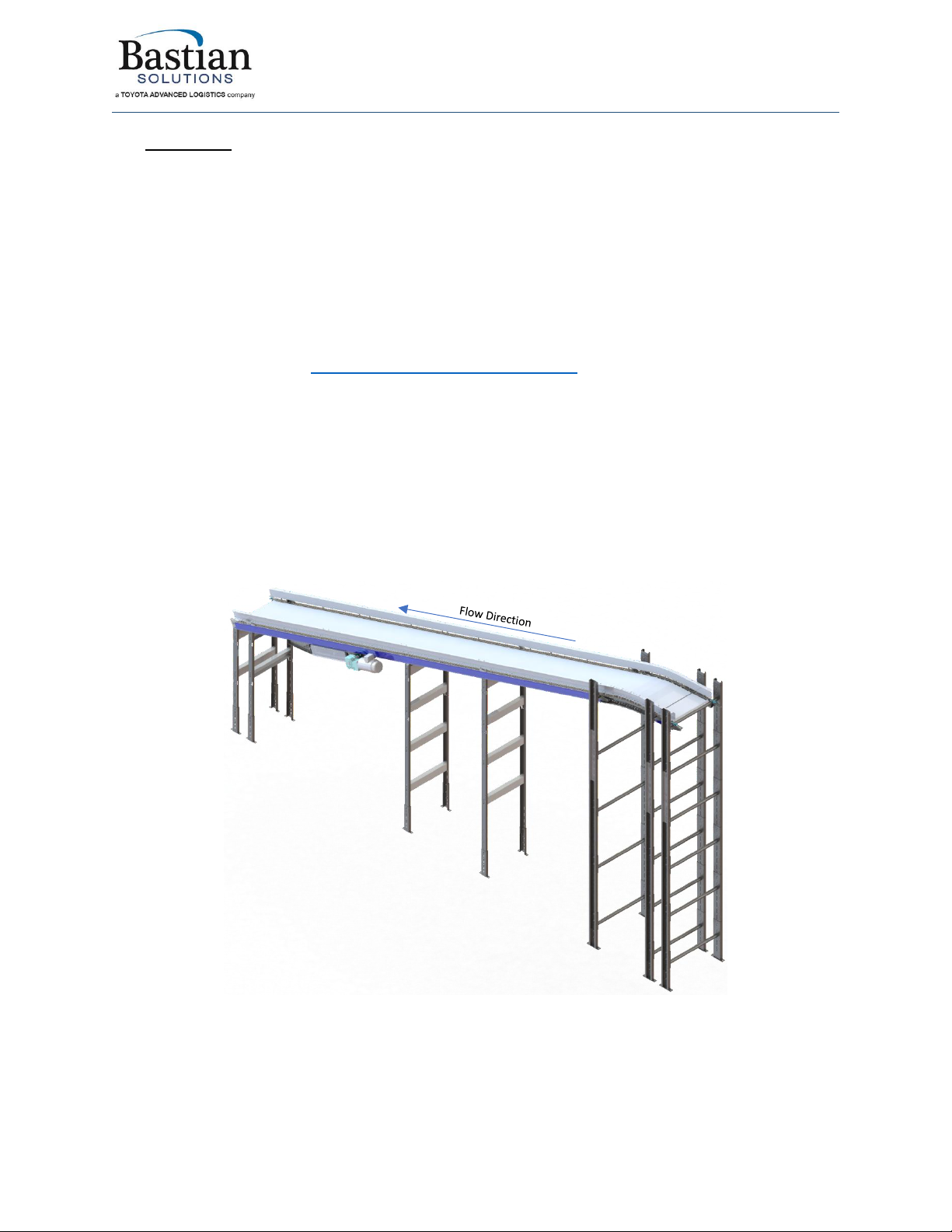
mark number “MK1100” illustrated in Figure 7.
Figure 7: BRBACI conveyor example with mark number "MK1100"
Installation & Maintenance Manual: BRBAC 1 HP
Published December 2019 Rev.A1 17
MK1100 has the following BRBAC sections, organized from upstream to downstream:
•SECTION 1 - BRBAC tail section, 12” OAL, 24” OAW
•SECTION 2 - BRBAC noseover section, 42” OAL, 24” OAW
•SECTION 3 - BRBAC bed section, 120” OAL, 24” OAW
•SECTION 4 - BRBAC bed section, 60” OAL, 24” OAW
•SECTION 5 - BRBAC drive section, 1HP motor side left, 120” OAL, 24” OAL
•SECTION 6 - BRBAC tail section, 12” OAL, 24” OAW
The BRBAC power feeder section is the last section in the list above but will be part of
a different mark number. In this example, the mark number for the BRBAC power
feeder is “MK1100-PF”.
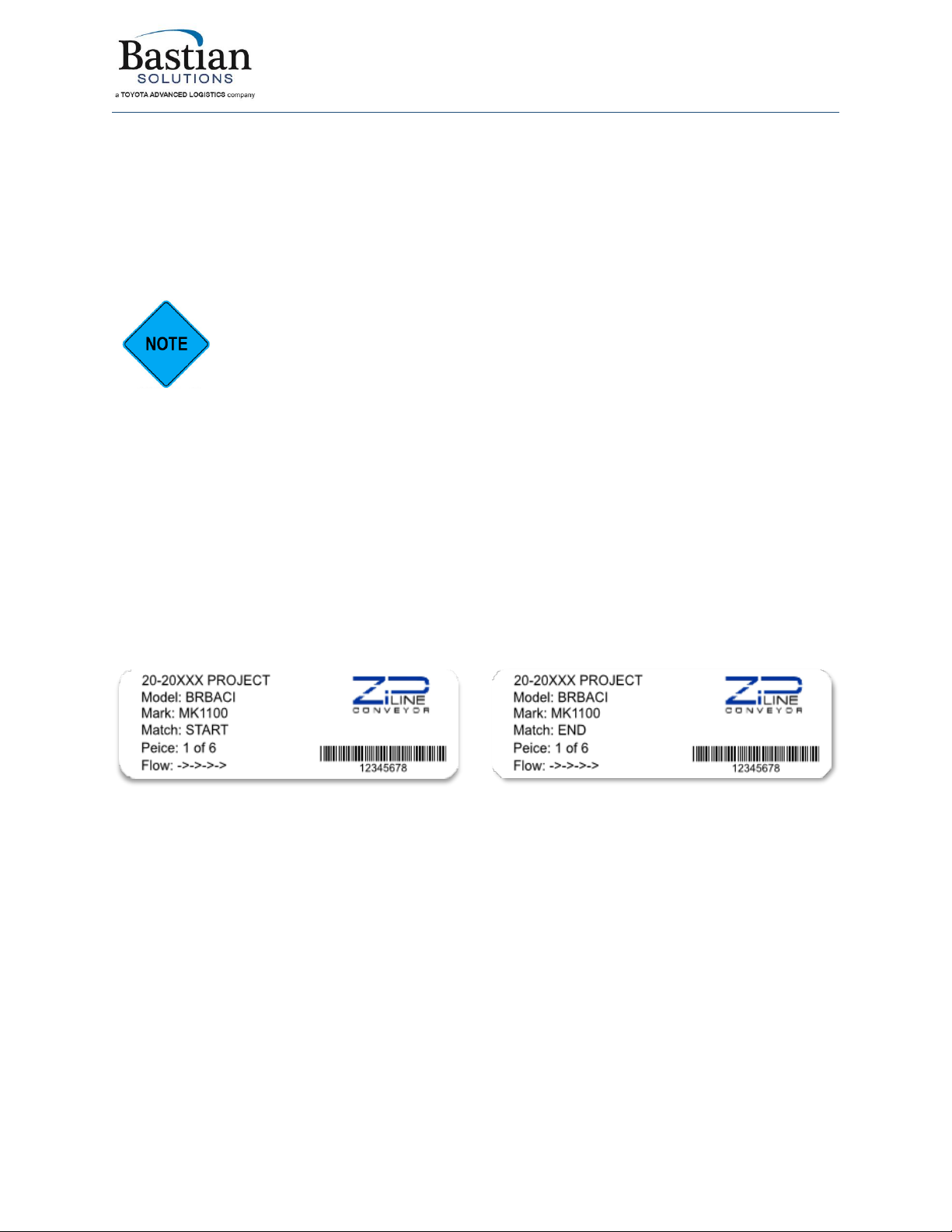
Each BRBAC section will have (2) stickers on the side frame. One sticker on the upstream side of the
conveyor frame, and the other sticker on the downstream side of the conveyor frame. Each sticker
contains the following information.
•ZiPline Project Number and Name
•Model Type
•Mark Number
•Match
•Piece
•Flow direction
Figure 8 illustrates the mark stickers on the side of the section 1 of MK1100 from the example above.
Figure 8: BRBAC mark stickers - section 1
4.2 Skid Contents
Skids will contain varying combinations of conveyor sections, support structures, accessories, and
pertinent hardware. For protection of product integrity during shipping accessories and supports may be
delivered on separate labeled skids. BRBAC accessories include the following:
•Floor supports/Polytier/Ceiling hangers (with mounting hardware)
•AC belt
•Underside bed covers (with mounting hardware)
•Guide rail (with mounting hardware)

Installation & Maintenance Manual: BRBAC 1 HP
Published December 2019 Rev.A1 18
4.3 Skid Documentation
All shipments will contain a Bill of Lading for the delivery company, a skid label, and a skid manifest. Skid
labels have the contents of each shipped item located on the skid. Figure 9 shows a sample of a skid
label. These stickers are placed on the surface of each skid.
Figure 9: Skid Sticker
BRBAC conveyor may arrive in multiple skids for the same mark number. The number of skids shipped is
dependent on the OAW and OAL of the mark number. The accessories for the BRBAC conveyor will ship
on separate skids.
Upon receiving the skid on site, please inspect for any visual damage of the equipment. If there are any
damages, please contact your ZiPline Conveyor representative with images and details of the skid.

Installation & Maintenance Manual: BRBAC 1 HP
Published December 2019 Rev.A1 19
5Installation
The installation supervisor on site should have the elevation and layout prints with detailed information
regarding the placement of conveyor sections and support structures. This information is not the
responsibility of ZiPline Conveyor to provide unless otherwise specified.
1. Clear the workspace around the portion of the layout selected for installation.
2. Ensure that the conveyor and accessory skids containing the correct BRBAC mark number are
unpacked and all components are accounted for.
3. Measure out from the constrained origin to start placement of supports. It is recommended that
snap chalk lines are used, or other methods of keeping a consistent line.
4. Use the elevation layouts to determine the conveyor top of conveyor surface and the
incline/decline angle of a mark section.
5. Place the support type that the layout designates. Each support type has a corresponding mark
sticker.
6. Check the flow direction on the mark stickers to ensure that conveyor is mounted properly.
7. Place the conveyor onto the support structure and fasten 3/8” -16 carriage bolts and serrated
flange nuts. Torque the serrated flange nuts to 31 ft-lb.
8. Refer to Section 5.5 to install and adjust the angle of the noseover section.
Do not lift the drive section of the conveyor using the lifting lug on the AC motor and
gearbox. This will cause damage to the gearbox and drive pulley. Use any mounting
point at the corners of the drive section.
9. Check for straightness and level of the conveyor sections. See instructions in section 5.2.
10. Route the supplied AC belt through the assembled conveyor. See instructions in section 5.3.
11. Attach any applicable accessories and connecting hardware to the mounted conveyor section.
12. Check that the upstream and downstream heights of the conveyor section agree with the
system layout instructions.
13. Secure the supports to the floor (or other permanent fixture).
ZiPline Conveyor does not provide hardware for attaching floor supports to the floor
or other permanent surface.
The floor supports of the installed BRBAC conveyor section must be permanently
secured prior to operation. Failure to do so can cause damage to the equipment and
injure personnel in the area. Please take necessary precautions during install.
5.1 Floor Support Location
When locating the floor support locations on site, ZiPline Conveyor recommends reviewing the
guidelines outlined in Bastian Solutions ZiPline Conveyor - Support Installation Manual.
There are two floor supports between the power feeder and the tail section. If you have a floor support
missing, contact your ZiPline conveyor representative.
Installation & Maintenance Manual: BRBAC 1 HP
Published December 2019 Rev.A1 20
5.2 Uniform Levelling and Straightness of Conveyor Section
The straightness of the BRBAC sections is critical to the performance of the conveyor. Please ensure that
the conveyor bed sections are checked for uniform level and straightness. To check for uniform levelling,
use a large level guide to confirm that all conveyor sections are appropriately levelled. To ensure that
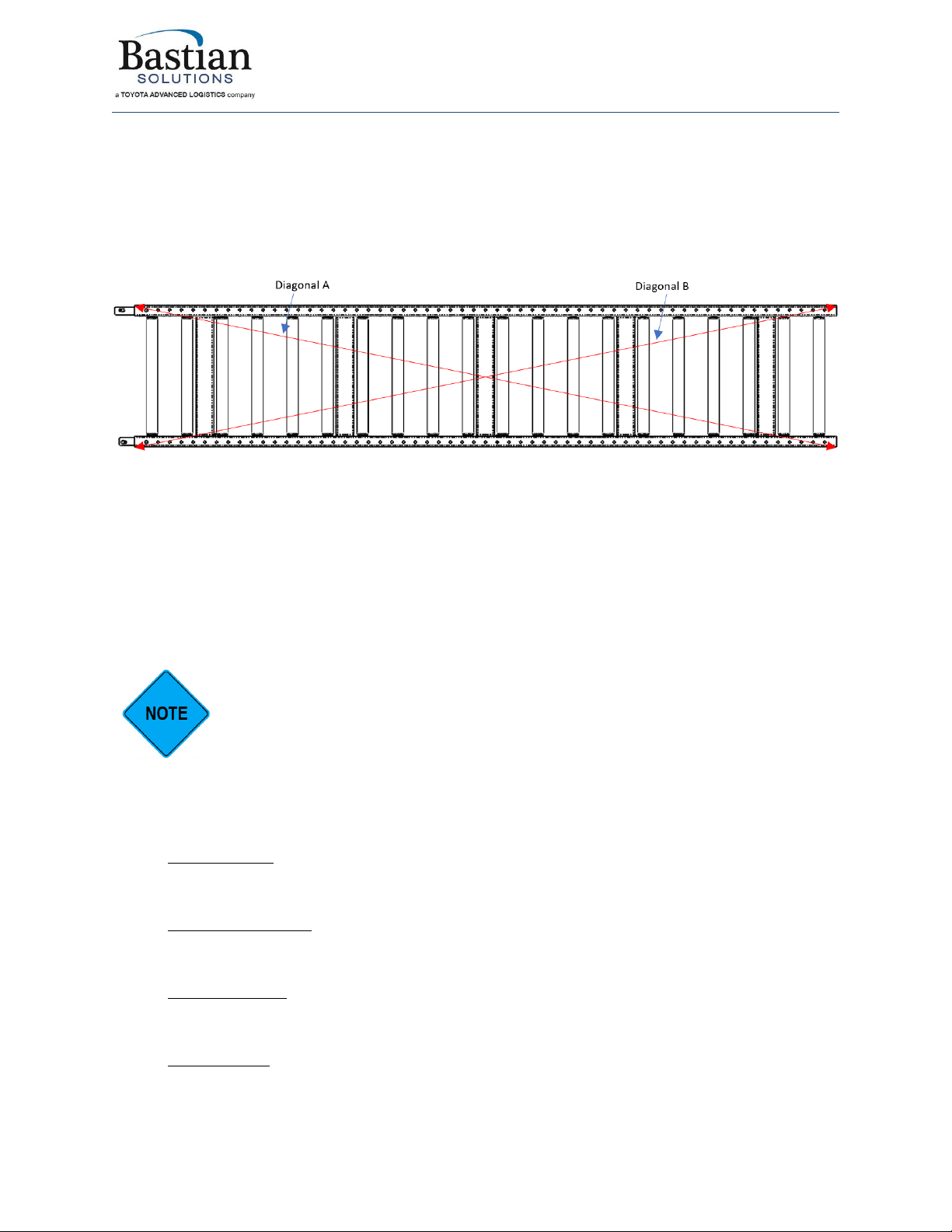
the conveyor sections are straight and square, measure the diagonals of each conveyor section. Figure
10 illustrates the diagonal measurement for the conveyor sections.
Figure 10: Diagonal measurement for conveyor section
•If the dimension of diagonal A and diagonal B of the bed section are within 1/16” of each other,
then the bed is sufficiently square.
•If the two diagonals of the bed section are different by more than 1/16”, adjust the splice plate
and floor support mounting hardware.
•If this adjustment is not sufficient, attach turnbuckles under the conveyor section and adjust for
square accordingly. Turnbuckles are typically installed to the bottom mounting holes of the
sideframe of a BRBAC section.
ZiPline Conveyor does not supply turnbuckle kits for additional section straightness
adjustments.
5.3 Installing the AC Belt
ZiPline Conveyor BRBAC comes available with four standard belt types. The belt and additional
documentation are as follows:
1. Rough Top Belt –The Rough top belt is a “trackmate”general purpose nonwoven PVC heavy
conveyor belt with a rough top (one side only). The product data sheet is called Habasit Heavy
Conveyor Belts TM120RT-B (Code: H250000385).
2. Longitudinal Rib Belt –The Longitudinal Rib Belt is a “trackmate”general purpose nonwoven
PVC heavy conveyor belt with a longitudinal groove structure. The product data sheet is called
Habasit Heavy Conveyor Belts TM120LR-B (Code: H250000441).
3. Brushed Top Belt –The brushed top is a rubber saturated “ulti-mate”nonwoven heavy conveyor
belt with an impregnated fleece on one side. The product sheet is called Habasit Heavy
Conveyor Belts UMS130SC-B (Code: H250000560).
4. Glide Top Belt –The glide top belt is a rubber conveyor and processing belt with a low friction
surface. The product sheet is called Habasit Product Data Sheet RGLIDE-T.
Table of contents
Other Bastian Solutions Accessories manuals


Popular Accessories manuals by other brands


ELEKTROBOCK
ELEKTROBOCK TS10 manual

Johnson Controls
Johnson Controls NS Series installation instructions

Cognex
Cognex In-Sight 2000 Training manual

ML
ML Knightsbridge SKR003A Installation & maintenance manual

PRÜFTECHNIK
PRÜFTECHNIK Fluke DBS 30 operating instructions

Novital
Novital Covatutto 108 User instruction


