Bastian Solutions RLVDC Manual
Installation and Maintenance Manual
Model: RLVDC
Effective February 2022
Rev. B

Installation and Maintenance Manual: RLVDC
Published February 2022
Rev. B
2
Contributions
ROLE
NAME
TITLE
Author Josh Foiles Design Engineer
Checker Ben Baker Senior Design Engineer
Approver Chris Perry Engineering Manager
Revisions
DATE
REVISION
DESCRIPTION
AUTHOR
10/21/2019
A1
Initial Document Creation
Josh Foiles
10/8/21 A2 Reformatted and Brand Update Mark Fishback
1/04/2022
Review B
MKT final draft
Mark Fishback
2/18/2022
B
Document formatting
Andrew W. Jones
Installation and Maintenance Manual: RLVDC
Published February 2022
Rev. B
3
Term and Acronym Definitions
TERM/ACRONYM
DEFINITION
2 Groove Roller format which uses O-Rings to transfer rotational motion from
one roller to another in DC conveyor.
BF
Between frame; this refers to the distance between conveyor bed
side frames.
Carton or Case
Term for conveyable items generally contained in cardboard boxes.
DC Direct current
DC Card A control card used to power and control the logic used when
operating a MDR in DC conveyor applications.
Discharge The point where cartons, cases, or totes exit a conveyor or similar
unit used in a material handling system.
Live
A zone of conveyor runs "live" when it runs whenever energized. It is
for this reason that live zones of conveyor do not have or need any
photoeyes or reflectors.
MDR
Motorized drive roller; DC powered conveyor roller with an internally
mounted motor which may be controlled via internal or external
commutation.
OAW Overall width of any given conveyor bed.
OD
Outer diameter of a circular, cylindrical, or arced body.
OSHA
Occupational Safety and Health Administration
Poly-V A band or roller hub format with longitudinal ribs used for power
transmission in DC conveyor applications.
PPE
Personal protective equipment
Roller
Powered or unpowered cylindrically-shaped material handling
component used for mechanical power transmission, a conveying
surface, and/or support for a belted conveying surface.
Side Cover
A PVC cover used to conceal and protect electrical components and
wiring from foreign debris and moving obstacles.
Side Frame Structural member used to support rotating components needed for
conveyor beds.
Singulation
The active separation of cartons, cases, or totes.
Wiz Nut A serrated flange nut used to cut into the surface of the component it
is tightened against.

Installation and Maintenance Manual: RLVDC
Published February 2022
Rev. B
4
Table of Contents
1Introduction............................................................................................................. 6
2OSHA and Safety .................................................................................................... 6
3Model: RLVDC......................................................................................................... 7
4Receiving................................................................................................................. 8
4.1 Mark Numbers ........................................................................................................................8
4.2 Skid Contents.........................................................................................................................9
4.3 Skid Documentation...............................................................................................................9
5Installation............................................................................................................. 10
6Maintenance and Operation................................................................................. 11
6.1 Safety During Operation ......................................................................................................11
6.2 Maintenance Schedule......................................................................................................... 11
6.2.1 Mechanical Service ............................................................................................................ 11
6.2.2 Electrical Service................................................................................................................ 12
6.2.3 Replacing Rollers ............................................................................................................... 13
6.2.4 Replacing Bands ................................................................................................................15
7Troubleshooting and Repair................................................................................ 17
8Standard Spare Parts ........................................................................................... 18
List of Figures
Figure 1: RLVDC General Arrangement Exploded View...........................................................................7
Figure 2: Mark Number Stickers...............................................................................................................8
Figure 3: Skid Sticker...............................................................................................................................9
Figure 4: MDR Removal-1 ..................................................................................................................... 13
Figure 5: MDR Removal-2 ..................................................................................................................... 14
Figure 6: MDR Removal-3 ..................................................................................................................... 14
Figure 7: Band Replacement .................................................................................................................16
Figure 8: RLVDC Spare Parts Exploded View........................................................................................ 18
List of Tables
Table 1: MDR Nut Torque Specifications ...............................................................................................11
Table 2: Troubleshooting Card Issues.................................................................................................... 17
Table 3: RLVDC Standard Spare Parts Table ........................................................................................ 18

Installation and Maintenance Manual: RLVDC
Published February 2022
Rev. B
5
Reference Documents
MANUFACTURER MANUAL
Interroll 9006 Hybrid Control for RollerDrive Manual
Interroll ZoneControl User Manual
Interroll DriveControl User Manual
Interroll EC100/110 User Manual
Interroll EC310 User Manual
Itoh Denki HBM604 User Manual
Itoh Denki IBE User Manual
Itoh Denki HB510 User Manual
Itoh Denki CBM105 User Manual
Itoh Denki Product Catalog
Bastian Solutions Side Cover and Guiderail Installation Manual
Bastian Solutions Support Installation Manual

Installation and Maintenance Manual: RLVDC
Published February 2022
Rev. B
6
1 Introduction
Thank you for choosing Bastian Solutions conveyor. The following manual serves as a guide for
installation, part replacement, and general maintenance for your material handling equipment. It is
important to read the manual and follow any instructions as it provides important safety information for
personnel and will maximize the longevity of the conveyor.
The information contained in this manual applies only to the products described. Uses, activities, or
processes related to installing or maintaining the equipment that are not explicitly described in this
manual are considered out of scope. Please contact Bastian Solutions for any questions or support that is
not clearly addressed in this document. Bastian Solutions is not responsible for misuse of the equipment
described in this manual or misuse of information in this manual. If you have any questions, contact
Bastian Solutions Customer Service at ConveyorSupport@bastiansolutiomns.com.
2 OSHA and Safety
Bastian Solutions is not responsible for ensuring that conveyors used in a system abide by OSHA
standards. Safety is of primary importance to our company, but as a product distributor we ask that
system integrators and end users conform with all applicable OSHA standards. We encourage that all
warnings in this manual are followed to avoid unnecessary risk.

Installation and Maintenance Manual: RLVDC
Published February 2022
Rev. B
7
3 Model: RLVDC
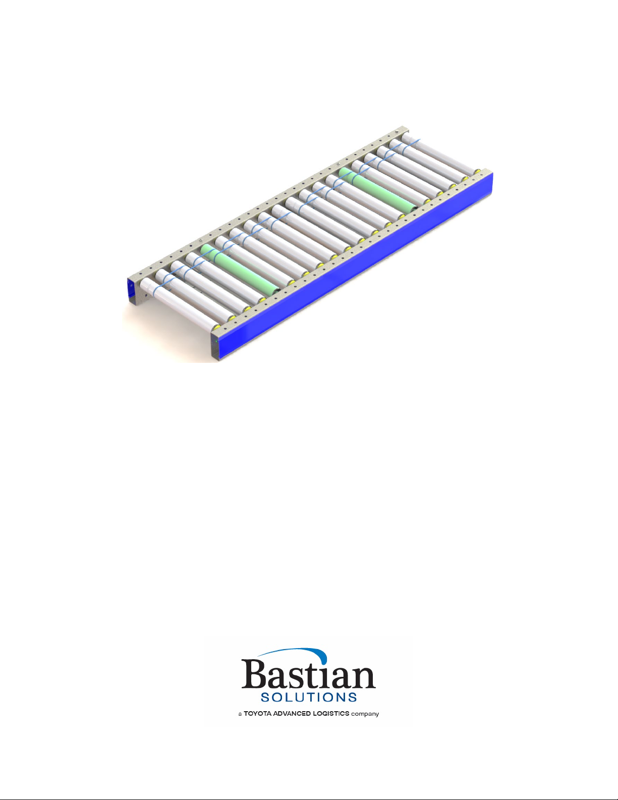
The Roller Live DC (RLVDC) Conveyor is designed with brushless 24V DC motor rollers. These rollers
are referred to as motor driven rollers (MDRs). RLVDC is used in applications where general transport is
all that is required. The rollers are “live” meaning they run continuously. The RLVDC is optimal for light to
medium products and works great with a variety of product sizes and types.
The model shown in Figure 1 serves as a reference to become familiar with the components and
terminology used in this manual. These terms will be used throughout the manual and are common
among many of the other Bastian Solutions’ conveyor product lines.
Figure 1: RLVDC General Arrangement Exploded View
The model in Figure 1 shows a 5’ RLVDC bed section. The RLVDC has 3” roller centers and has (2) 30”
zones. Each zone is made up of (9) rollers and (1) MDR. The rollers and MDRs each have two grooves
that allow them to be banded together with O-rings. Each zone has an MDR that needs to be connected
to a control card. The model shown in Figure 1 contains a dual zone card. These can be used to control
two zones. While this is a standard configuration, another very common configuration is one zone per
card.

Installation and Maintenance Manual: RLVDC
Published February 2022
Rev. B
8
4 Receiving
Upon delivery of any Bastian Solutions conveyor, please review and check the following:
•The quantity of items received against the Bill of Lading.
•Complete a visual inspection of equipment to determine any damage that may have occurred
during shipping. If damage is present, document with pictures.
•Review Mark Number information and layout locations. More information can be found in
subsection 4.1
If there are any missing or damaged components contact your Bastian Solutions’ conveyor representative
with as much detail as possible. If you are unsure of your Bastian Solutions’ conveyor representative,
please contact Bastian Solutions Customer Service at ConveyorSupport@bastiansolutiomns.com.
4.1 Mark Numbers
A mark number is a specific number given to a piece of equipment. A mark number is usually made up of
a single product line (RZPDC, RLVDC, BZPDC, etc.) but can contain many bed section lengths. They can
range from two inches to hundreds of feet. The mark number is used to help identify where the piece of
equipment will go within the system layout.
Every bed section of conveyor will have (2) stickers. One sticker on the infeed end of the bed, and one
sticker on the discharge end of the bed. Each sticker will contain the following information:
•Project Number and Name
•Model Type
•Mark Number
•Match
•Piece
•Flow
Figure 2 shows stickers that would appear on an RZPDC that has two bed sections.
Figure 2: Mark Number Stickers
The match field on the stickers is used to indicate if two bed sections are to be spliced to one another. As
shown in Figure 2, the stickers where the two beds splice together both contain “Match: 1”. The piece
field defines the bed section number within the mark. The flow refers to the direction of product flow along
the conveyor system.
Installation and Maintenance Manual: RLVDC
Published February 2022
Rev. B
9
4.2 Skid Contents
Skids will contain varying combinations of conveyor sections, support structures, accessories, and
pertinent hardware. For protection of product integrity during shipping, accessories and supports may be
delivered on separate but labeled skids.
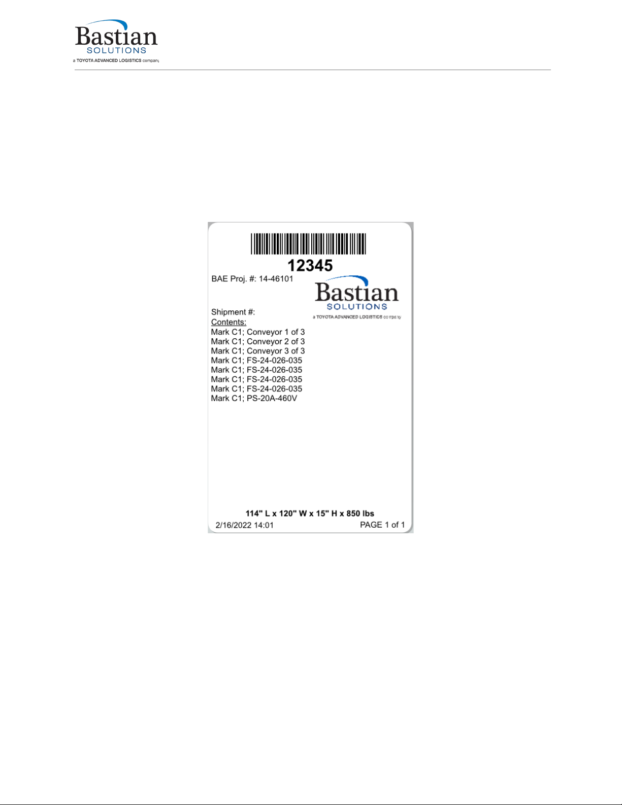
4.3 Skid Documentation
All shipments will contain a Bill of Lading for the delivery company, a skid label, and a skid manifest. Skid
labels have the contents of each shipped item located on the skid. Figure 3 shows a sample of a skid
label. These stickers are placed on the surface of each skid.
Figure 3: Skid Sticker

Installation and Maintenance Manual: RLVDC
Published February 2022
Rev. B
10
5 Installation
The installation supervisor should have elevation and layout prints with detailed information regarding the
placement of conveyor sections and support structures. This information is not the responsibility of
Bastian Solutions to provide unless otherwise specified.
1. Clear the workspace around the portion of the layout selected for installation.
2. Measure out from a constrained origin to start placement of supports. It is recommended that
snap chalk lines are used, or other methods of keeping a consistent line.
3. Use elevation layouts to determine the conveyor’s top of conveying surface.
4. Place the support type that the layout designates. Each support type has a corresponding mark
sticker.
5. Check the flow direction on the mark stickers to ensure that conveyors are mounted properly.
6. Place the conveyor onto the support structure and fasten it securely using the 3/8”-16 carriage
bolts and wiz nuts provided. The recommended torque specification is 26ft-lbs.
7. Attach any guiderail or miscellaneous accessories. For information on guiderail installation,
please reference the “Bastian Solutions Conveyor Side Cover and Guiderail Installation Manual”
8. Check that the height of the infeed and discharge ends are correct per the system layout.
9. Lag the supports to the floor (or other permanent fixture).
Refer to the “Bastian Solutions Conveyor Support Installation Manual” for
more information on installing conveyor.

Installation and Maintenance Manual: RLVDC
Published February 2022
Rev. B
11
6 Maintenance and Operation
The longevity and proper functionality of Bastian Solutions conveyor is based upon standard operating
practices and general maintenance of equipment. Setting up a regular maintenance schedule will help to
ensure that products comply with the equipment’s warranty. Lockout/Tagout procedures should be
implemented before performing any maintenance.
6.1 Safety During Operation
The list below explains a series of recommended precautions that should be taken when personnel are
near the equipment. This list is not intended to be the only precautions taken, but it serves as a guide of
important steps to follow.
•Only fully trained employees should operate or perform maintenance on the conveyors. Proper
training should include the detailed description of fail-safes, stopping devices, or other emergency
regulations put in place.
•WARNING stickers should be replaced if worn or damaged.
•All personnel in the area should be alerted prior to starting any conveyor at all times. This process
may vary depending on the conditions and layout of the site, but it should use audible and visual
cues and all personnel should be made aware of the protocol.
•Operators should inspect the conveyor for damage, foreign objects, and verify all personnel is
clear of the equipment prior to engaging drive.
•Ensure that all areas are clear of objects prior to loading and unloading.
•No personnel should ever ride, climb, step, sit on, or otherwise put body weight on the conveyor.
Doing so puts both personnel and equipment at risk.
•Maintenance should be performed at regular intervals to assure the safety of operators and the
longest life of components. Should a component break during operation or prior to operation, then
lockout/tagout instructions should be performed immediately to prevent exposure to hazards.
6.2 Maintenance Schedule
To prolong the life of the material handling equipment and reduce the risk of potential safety
hazards, it is vital that a preventative maintenance program be set in place and followed. The
following instructions will help identify key areas requiring maintenance.
6.2.1 Mechanical Service
•An auditory inspection of the equipment should be performed to identify any unusual noise that
may indicate that there is a problem with the equipment.
•Check all nuts and bolts to ensure bolts remain tight. MDR nuts should be torqued using a torque
wrench to each MDR’s torque specs. Please reference Table 1 for a list of common MDRs and
their torque requirements.
•O-rings/bands should be inspected for excessive wear, stretching or slip and replaced as
necessary.
•The recommended interval for maintenance is at least once every 6 months.
Table 1: MDR Nut Torque Specifications
MDR
MDR NUT TORQUE SPECS
Interroll EC100/110
30 ft-lbs
Interroll EC310
50 ft-lbs
Itoh Denki PM486FE/FP
23 ft-lbs
Installation and Maintenance Manual: RLVDC
Published February 2022
Rev. B
12
6.2.2 Electrical Service
•All Bastian Solutions’ conveyor DC products operate at either 24V or 48V, nominally.
•If adjustment of control card settings is required, refer to the respective technical manual listed in
Reference Documents, or contact Bastian Solutions Customer Service at
ConveyorSupport@bastiansolutiomns.com.
•If there is a need to replace a DC control card, perform the following:
oDe-energize associated power supply and remove respective side cover (if applicable)
oAdjust settings of replacement control card to match those of the existing control card.
oRemove the existing control card from the side frame for ease of cable disconnection:
If the existing control card has a mounting plate, remove wiz nut securing control
card mounting plate to side frame.
If the existing control card is secured to the conveyor side frame with anything
other than a mounting plate, install new securing material on the new control card
and re-use the securing material on the side frame.
oOne at a time, remove all cables and connectors and plug them into the same respective
connection port on the new control card.
oIf the control card in question has a mounting plate, remove the mounting plate secured
to the existing control card, and install it on the new control card (if the new control card
does not already have a mounting plate installed on it).
oInstall the new control card on the conveyor side frame
oRe-energize associated power supply, check the lane for proper system functionality, and
reinstall respective side cover (if applicable).
Never “hot swap” control cards (i.e. disconnect and reconnect power
connector on control cards without de-energizing respective power supply).
When doing this, there is an increased risk of damaging the new control
card.
There is always a possibility that control card errors are being caused by
faulty communication cables (RJ45, CAT5, or CAT6), or problems with
adjacent cards connected via the communication cables.
•If cards or card fuses are blowing:
oEnsure there are no shorts in system power wiring
oEnsure all conveyor side frames are electrically bonded and provided a direct connection
to earth ground
oEnsure control card DIP switch settings match those needed for zone MDR (if applicable)
oIf associated conveyor zone has powered brake roller, ensure it is electrically connected
oIf problems persist, refer to the respective technical manual listed in the Reference
Documents section of this document.
•If experiencing any other electrical problems with Bastian Solutions DC conveyor, contact Bastian
Solutions Customer Service at ConveyorSupport@bastiansolutiomns.com.
When performing electrical work on Bastian Solutions conveyor, ensure
adherence to all applicable OSHA standards.

Installation and Maintenance Manual: RLVDC
Published February 2022
Rev. B
13
6.2.3 Replacing Rollers
If polyvee bands or 2” roller spacing is being used, it will often be easier to
remove a roller/band by disassembling the zone roller-by-roller until reaching
the roller/ band that is being replaced. The directions in this segment refer to
replacement of rollers within a 3” roller center conveyor.
For motor driven rollers (MDRs):
1. Follow the lockout/tagout procedure in place to ensure safety.
2. Remove the side cover from the intended work area.
3. Loosen the MDR nut located on the cable side of the roller.
4. Pull the MDR bracket away from the frame. Refer to Figure 4
Figure 4: MDR Removal-1

Installation and Maintenance Manual: RLVDC
Published February 2022
Rev. B
14
5. Apply pressure on the end of the hex shaft opposite the cable using a small diameter punch or
similar tool until the shaft clears the frame. Be careful NOT to apply a side load to the hex shaft.
Refer to Figure 5.
Figure 5: MDR Removal-2
6. Provide upward force on the roller body until the hex is sitting above the side frame. Refer to
Figure 6. (A putty knife or other flat surface tool is recommended to be placed between the hex
shaft and the inside of the frame. This will help protect the paint on the side frame.)
Figure 6: MDR Removal-3

Installation and Maintenance Manual: RLVDC
Published February 2022
Rev. B
15
7. Pull the threaded shaft out of the side frame.
8. Pull the MDR away from the bands until the MDR is completely free of the side frames and
bands.
9. Slide the new MDR cable through the MDR washer and guide it through the hex hole.
10. Place the MDR bracket back onto the threaded shaft.
11. Guide the MDR back through the existing bands.
12. Use a putty knife or other flat surface tool to guide the hex shaft into the hex hole.
13. Fasten the MDR nut using a torque wrench to the appropriate value given in Table 1.
14. Plug the MDR into the card.
15. Replace the side cover.
For standard rollers:
1. Follow the lockout/tagout procedure in place to ensure safety.
2. Remove the side cover from the intended work area.
3. Apply pressure on the end of the hex shaft opposite the wiring using a small diameter punch or
similar tool until the shaft clears the frame. Be careful NOT to apply a side load to the hex shaft.
Refer to Figure 5.
4. Provide upward force on the roller body until the hex is sitting above the side frame. Refer to
Figure 6. (A putty knife or other flat surface tool is recommended to be placed between the hex
shaft and the inside of the frame. This will help protect the paint on the side frame.)
5. Remove the hex shaft from the opposite hex hole
6. Pull the roller away from the bands until the roller is completely free of the side frames and bands.
7. Slide the new roller through the bands.
8. Once the new roller is through both bands, guide the hex shaft into the hex hole.
9. After the hex shaft is in the hex hole, the opposite side shaft can be inserted into the appropriate
hex hole. Use the roller’s length as leverage to aid in this step.
10. Use a putty knife or other flat surface tool to guide the hex shaft into the opposite hex hole.
11. Replace the side cover.
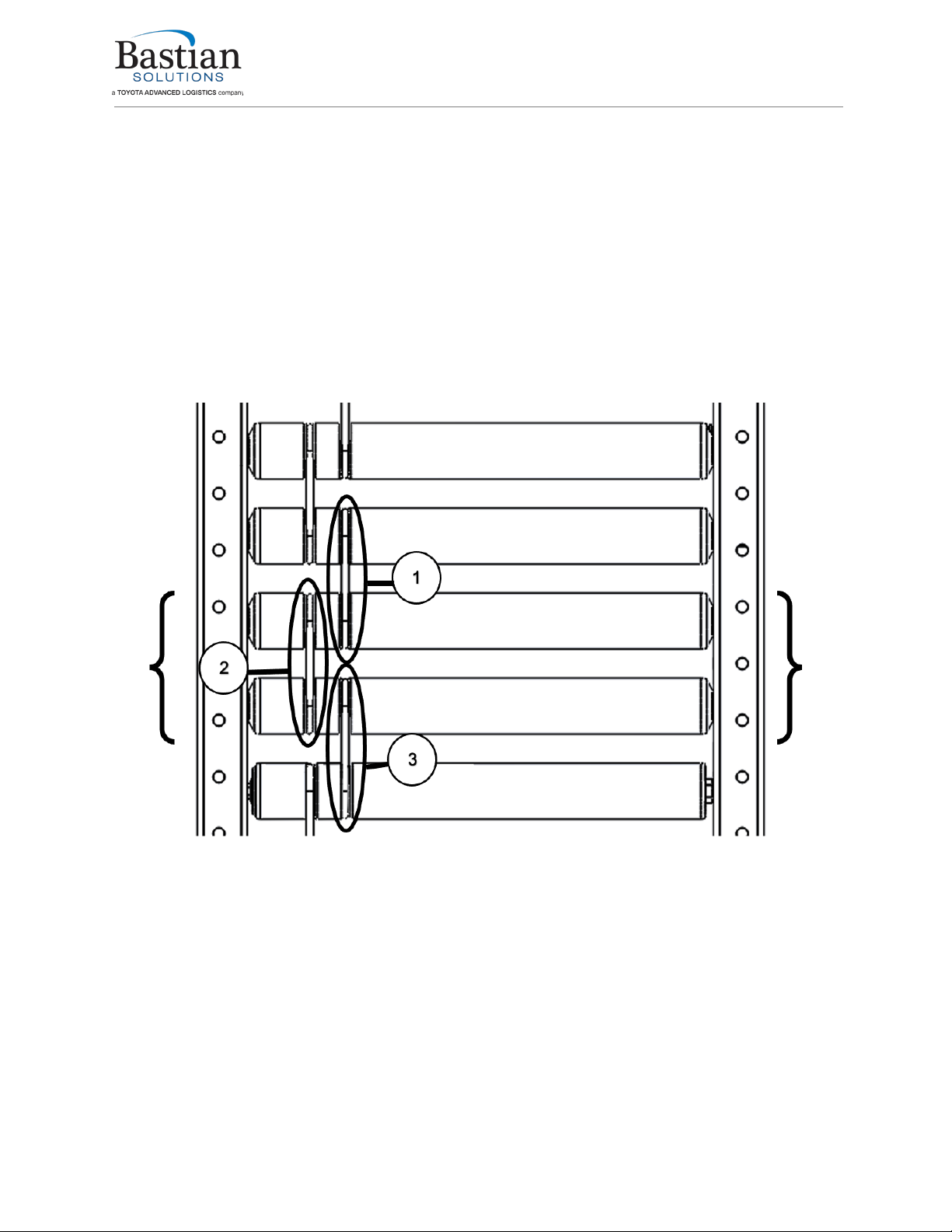
6.2.4 Replacing Bands
1. Follow the lockout/tagout procedure in place to ensure safety
2. Remove the side cover from the intended work area.
3. If the band being replaced is on the outside groove/hub of the roller as shown in circle 2 of Figure
7 the two rollers within the brackets will need to be removed. Follow the roller removal steps in
the roller replacement procedure.
4. After the rollers have been removed, slide one of the rollers that was removed through the band
in circle 1 of Figure 7.
5. After the roller is within circle 1, slide the new band onto the same roller on the groove side of the
roller. (Left side in Figure 7)
6. Use the new band to help guide the hex shaft into the hex hole.
This method is effective but requires a large amount of tension in the bands.
Because of this tension fingers can be pinched if not done carefully.
7. Once the groove side hex shaft (Left side in Figure 7) is within the hex hole, insert the opposite
side hex shaft into the appropriate hex hole. Use the roller’s length as leverage to aid in this step.
As called out in the roller replacement procedure, use a putty knife or other flat surface tool to
protect the paint on the side frame.
8. After the first roller has successfully been re-installed, install the second roller.
Installation and Maintenance Manual: RLVDC
Published February 2022
Rev. B
16
9. Slide the roller through the old band in circle 3 of Figure 7. Then slide the roller through the new
band. (This step can be difficult as the bands are tight.)
10. Once the roller has both bands around it, guide the hex shaft into the hex hole.
11. Once the groove side hex shaft (Left side in Figure 7) is within the hex hole, insert the opposite
side hex shaft into the appropriate hex hole. Use the roller’s length as leverage to aid in this step.
As called out in the roller replacement procedure, use a putty knife or other flat surface tool to
protect the paint on the side frame.
12. If the band being replaced is on the inside groove/hub of the roller as shown in the blue circle of
Figure 7, then remove the hex shafts opposite the groove/hub.
13. Roll the band being replaced down the length of the two rollers.
14. Roll the new band up the length of the two rollers.
15. Re-insert the hex shafts into the appropriate hex holes.
16. Replace side covers.
Figure 7: Band Replacement

Installation and Maintenance Manual: RLVDC
Published February 2022
Rev. B
17
7 Troubleshooting and Repair
Many issues that may arise with Bastian Solutions conveyor can be corrected with minimal field repairs.
Bastian Solutions encourages using the following troubleshooting techniques before contacting a Bastian
Solutions representative as these are the same techniques used by our field service engineers. To assist
in data collection, Bastian Solutions asks that any issues that arise be recorded in a log, with the mark
number, a description of the issue, and the steps taken to resolve the issue. Table 2 gives direction for
retroreflective photoeyes. If a diffuse photoeye is being used, verify that the sensor is set to Light Mode(L)
(Arrow pointed at L on photoeye).
Table 2: Troubleshooting Card Issues
ERROR
CAUSE
ACTION
Conveyor flow direction,
speed, or acceleration is
incorrect
Incorrect DIP switch settings
Check card manufacturer’s
literature to verify proper switch
configuration.
Zone not operating
No power supply Check that the power supply is
on and wired to the card
Fuse is blown Check LED lights and replace
the fuse if confirmed short
Incorrect DIP switch setting
Check card manufacturer’s
literature to verify proper switch
configuration
System reverses or jogs
without prompting
Fuse is blown
Check the fuses of all cards in
the immediate system
Incorrect DIP switch setting
Check card manufacturer’s
literature to verify proper switch
configuration
Communication cable incorrectly
connected or faults
Check com cables and replace if
faulty.
System turns off when several
zones are in use at the same
time
Power supply insufficient
Check the number of zones per
power supply
Check that the power supply
and AC voltage source are
working properly and installed
correctly

Installation and Maintenance Manual: RLVDC
Published February 2022
Rev. B
18
8 Standard Spare Parts
Figure 8: RLVDC Spare Parts Exploded View
Table 3: RLVDC Standard Spare Parts Table
REF. NO. DESCRIPTION COMMON CONFIGURATIONS
1ROLLERS
2 GROOVE
POLYVEE
2BANDS
O-RING- 2IN ROLLER SPACING
O-RING – 3IN ROLLER SPACING
POLYVEE- 2IN ROLLER SPACING
POLYVEE- 3IN ROLLER SPACING
3MOTOR DRIVEN ROLLERS (MDRS)
2 GROOVE/POLYVEE – INTERROLL EC100
2 GROOVE/POLYVEE – INTERROLL EC110
2 GROOVE/POLYVEE – INTERROLL EC310
2 GROOVE/POLYVEE – ITOH PM486FE
2 GROOVE/POLYVEE – ITOH PM486FP

Installation and Maintenance Manual: RLVDC
Published February 2022
Rev. B
19
Bastian Solutions Conveyor Installation and Maintenance Manual
Model: Bastian Solutions RLVDC Conveyor
© 2022 Bastian Solutions, LLC
All rights reserved. This document contains information considered proprietary to Bastian Solutions. It
may not be duplicated, used, or disclosed without written permission from Bastian Solutions. It may not
be used in whole or in part for any purpose other than its intended purpose as an operation, installation,
and maintenance manual for the product or products described herein. Bastian Solutions reserves the
right to revise the contents of this document as necessary.
Bastian Solutions, LLC
1821 Bastian Court
Westfield, IN 46074
Customer Support: ConveyorSupport@bastiansolutiomns.com
This manual suits for next models
1
Table of contents
Other Bastian Solutions Accessories manuals


